
Subscribe to Our Youtube Channel
Related Manuals for Munters TU600


Summary of Contents for Munters TU600
- Page 1 Manual for use and maintenance + CE Declaration of conformity TU600 - TU800 Chimney fan Ag/MIT/UmGB-2181-04/14 rev 1.0...
- Page 2 Munters A/S reserves the right to effect modifications to the apparatus in accordance with technical and legal developments. © Munters AB, 2014...
-
Page 3: Table Of Contents
3.2 Packaging and transport of assembled fans 3.3 Structure OPERATING CONDITIONS INSTALLATION 5.1 Electrical connections for standard motor 5.2 Electrical connections for Munters Drive motor 5.3 Assembly instructions 5.4 Placement of fans 5.5 Electrical wiring COMMISSIONING © Munters AB, 2014... - Page 4 Index TECHNICAL DATA 7.1 Dimensions 7.2 Technical specification 7.3 Motor specifications 7.4 Data for Fan Eco Design Directive MAINTENANCE 8.1 Introduction 8.2 Cleaning SPARE PART LIST WARRANTY © Munters AB, 2014...
-
Page 5: Ce Declaration
DECLARES ON ITS OWN RESPONSIBILITY THAT THE APPARATUS Chimney fan designed for moving air to control temperature Designation and humidity in livestock. Model TU600 - TU800 Year of manufacture 2014 CONFORMS WITH THE ESSENTIAL SAFETY REqUIREMENTS STATED BY APPARATUS DIRECTIvE 2006/42/EC AND PERFORMANCE REqUIREMENTS COMPLY WITH THE ERP DIRECTIvE 2009/125/CE. -
Page 6: Disclaimer
The information contained herein has been prepared by qualified experts within Munters. While we believe the information is accurate and complete, we make no warranty or representation for any particular purposes. The information is offered in good faith and with the understanding that any use of the units or accessories in breach of the directions and warnings in this document is at the sole discretion and risk of the user. -
Page 7: Safety Aspects
Safety aspects 2.1 General The safety of fans is assured by Munters in compliance with the safety requirements indicated by the CE label. Safe functioning is assured only when the installation procedure and the instructions for use have been carefully followed. -
Page 8: Before Using
• motor: single-phase or three-phases; 50 Hz; F class winding insulation, IP 55 IEC protective class; • a version with high efficiency Munters Drive motor is available for TU600 and TU 800; • a plastic damper assuring tightenness to air when fan is not in operation. -
Page 9: Operating Conditions
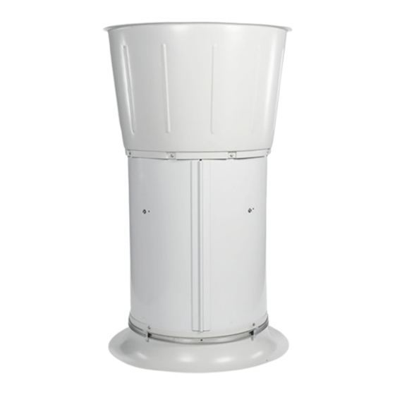
Operating conditions Chimney fans, such as the TU600 and TU800, are products to to extract the air from a structure, thereby creating air movement inside the structure which helps to keep under control temperature in livestock buildings. Normal ambient temperature limits are –25°C to +50°C. Maximum altitude is 1000m above sea level. Should a fan be required to operate at a higher altitude, the loss in mass flow (heat removing capacity) due to lower air density should be taken into consideration. -
Page 10: Installation
1x230v ac fig.1 With frequency inverter 3x400v ac fig.2 5.2 Electrical connections for Munters Drive motor 1. Cover of controller housing; 2. 3 cable glands (3 x M16 ) included; 3. cable entry points with plastic fastener; 4. mains connection;... -
Page 11: Assembly Instructions
• remants from installation and foreign object may not remain on the inside. Warning For detailed electric connection instructions for Munters Drive motor refer to Munters Drive motor manual. 5.3 Assembly instructions Click the two rolling junctions together as in the zoom showing the cut of the pipe. - Page 12 Mount 3 pcs. motor fittings inside the pipe in rough- bored holes. (Figure illustrates motor suspension and cut of the pipe). fig.7 • Fasten the fan on the shaft. • Mount the flange on the motor with 4 set screw 6x16. fig.8 © Munters AB, 2014...
-
Page 13: Placement Of Fans
Chapter5 Installation 5.4 Placement of fans ROOF INSTALLATION fig.9 CEILING INSTALLATION fig.10 FLOOR INSIDE INSTALLATION fig.11 © Munters AB, 2014... -
Page 14: Electrical Wiring
For safety reasons the overload switch can be locked by a padlock, not supplied by Munters. The installer must provide a suitable control box in compliance with requirements specified by EN 60204 rules. - Page 15 Below are suggested wiring diagrams for connecting the fan to the mains electrical supply. These diagrams are however subject to local laws and regulations and should be modified if necessary to comply with such laws and regulations. fig.15 fig.16 = Overload protection switch = Circuit breaker = Fan motor © Munters AB, 2014...
- Page 16 Failure to operate the fan with an overload protection device will render the motor guarantee null and void. Such motor overload protection devices can be note ordered from Munters and be supplied with the fans. Standard fan motors have the following voltage and frequency: • 230/400v three-phase 50 Hz •...
-
Page 17: Commissioning
Wait until the electrical power has been Warning switched off and the fan has come to a complete stand still. Lock the electrical switch in the off position with a pad lock while working on the fan. © Munters AB, 2014... - Page 18 Technical data 7.1 Dimensions ROOF/CEILING DIMENSIONS fig.17 Model TU600 1,830 1,000 TU800 1,830 1,100 1,100 1,000 FLOOR INSIDE/OUTSIDE DIMENSIONS fig.19 Model TU600 3,830 1,000 TU800 3,830 1,100 1,100 1,000 © Munters AB, 2014...
- Page 19 Chapter7 Technical data 7.2 Technical specifications © Munters AB, 2014...
- Page 20 Product information requirements → optional (according to anneX i - 3.2 of regulation) Fan description TU600 STD 250W 27.5 static 36 (--) 8,150 58.9 TU600 MUNTERS DRIvE 660W 41.1 static 36 (40) 9,266 80.1 TU800 STD 370W 34.2 static 41.4 36 (40) 11,420 77.7...
-
Page 21: Maintenance
Warning itself. In this particular event the manufacturer refuses all responsibility on consequent damages caused to things and people and considers any kind of warranty lost. © Munters AB, 2014... -
Page 22: Spare Part List
Spare part list TU600 MUNTERS DRIvE © Munters AB, 2014... - Page 23 TU600 MUNTERS DRIvE CONE Ø600 SELF-TAPPINGSCREW 4.8×19 MUNTERS DRIvE MOTOR MOTOR SUPPORT SELF-LOCKING NUT M8 SLOTTED PAN HEAD SCREW M8×16 MUNTERS DRIvE MOTOR CAGE Ø600 HExAGON SCREW M6x16 PROPELLER Ø600 WASHER Ø5x20 SPRING WASHER Ø5 HExAGON SCREW M5x16 FAN BODY Ø600 BUSH FOR DAMPER SHAFT WASHER Ø6×18...
- Page 24 Chapter9 Spare part list TU600STD © Munters AB, 2014...
- Page 25 FAN BODY Ø600 BUSH FOR DAMPER SHAFT WASHER Ø6×18 SELF-LOCKING NUT M6 AxLE DAMPER Ø600 ACTUATOR SHAFT AIR CONvEYOR Ø600 SLOTTED PAN HEAD SCREW M6×16 TABLE 3: PROPELLER/MOTOR GROUP MOTOR PROPELLER POWER PHASES×TENSION BLADES No. INCLINATION [°] 1×230 © Munters AB, 2014...
- Page 26 Chapter9 Spare part list TU800 MUNTERS DRIvE © Munters AB, 2014...
- Page 27 TU800 MUNTERS DRIvE CONE Ø800 SELF-TAPPINGSCREW 4.8×19 MUNTERS DRIvE MOTOR SELF-LOCKING NUT M8 MOTOR SUPPORT SLOTTED PAN HEAD SCREW M8×16 MUNTERS DRIvE MOTOR CAGE Ø800 HExAGON SCREW M6x16 PROPELLER Ø800 WASHER Ø5x20 SPRING WASHER Ø5 HExAGON SCREW M5x16 FAN BODY Ø800 BUSH FOR DAMPER SHAFT WASHER Ø6×18...
- Page 28 Chapter9 Spare part list TU800STD © Munters AB, 2014...
- Page 29 BUSH FOR DAMPER SHAFT WASHER Ø6×18 SELF-LOCKING NUT M6 AxLE DAMPER Ø800 ACTUATOR SHAFT AIR CONvEYOR Ø800 SLOTTED PAN HEAD SCREW M6×16 TABLE 2: PROPELLER/MOTOR GROUP MOTOR PROPELLER POWER PHASES×TENSION BLADES No. INCLINATION [°] 1×230 3×400 1×230 © Munters AB, 2014...
- Page 30 Munters plant was required: if this is not done, the user is fully responsible for the damage which they could suffer.
- Page 31 Requests for technical assistance and spare parts must be made directly to the manufacturer, at the following address: Munters A/S Nordvestvej, 3 9600 Aars, Denmark Tel: +45 986 233 11 Fax: +45 986 213 54 aghort@munters.dk © Munters AB, 2014...
- Page 32 TU600 and TU800 exhaust fans are developed and produced by Munters A/S, Denmark www.munters.com Australia Munters Pty Limited, Phone +61 2 8843 1594, Brazil Munters Brasil Industria e Comercio Ltda, Phone +55 41 3317 5050, Canada Munters Corporation Mason, Phone +1 517 676 7070, China Munters Air Treatment Equipment (Beijing) Co.
Need help?
Do you have a question about the TU600 and is the answer not in the manual?
Questions and answers