Table of Contents
Advertisement
T
TM
intelligent motion systems, inc.
Excellence in Motion
TM
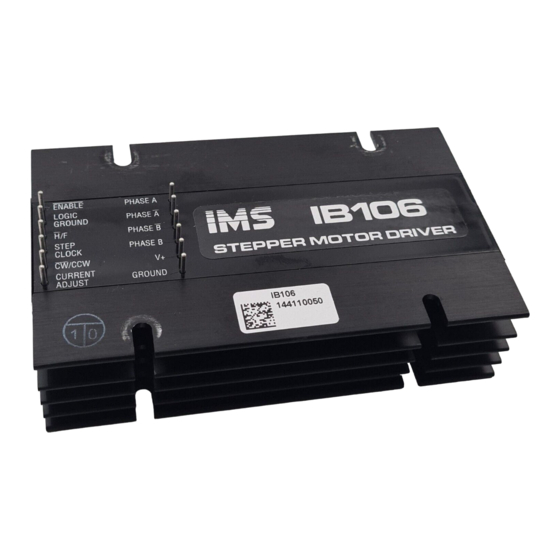
IBSERIES
HALF/FULL STEP STEPPING MOTOR DRIVERS
IB462 ' ' ' ' ' IB463 ' ' ' ' ' IB104 ' ' ' ' ' IB106 ' ' ' ' ' IB1010
OPERA TING INSTRUCTIONS
370 N. MAIN ST., PO BOX 457, MARLBOROUGH, CT 06447
PH. (860) 295-6102, FAX (860) 295-6107
Internet: http://www.imshome.com, E-Mail: info@imshome.com
Advertisement
Table of Contents

Subscribe to Our Youtube Channel
Summary of Contents for Intelligent Motion Systems IB Series
- Page 1 Excellence in Motion IBSERIES HALF/FULL STEP STEPPING MOTOR DRIVERS IB462 ' ' ' ' ' IB463 ' ' ' ' ' IB104 ' ' ' ' ' IB106 ' ' ' ' ' IB1010 OPERA TING INSTRUCTIONS 370 N.
- Page 2 Intelligent Motion Systems, Inc., reserves the right to make changes without further notice to any products herein to improve reliability, function or design. Intelligent Motion Systems, Inc., does not assume any liability arising out of the application or use of any product or circuit described herein; niether does it convey any license under its patent rights of others.
-
Page 3: Table Of Contents
Contents IMPORTANT! READ THIS FIRST! ............5 The Product Manual ..................5 Connecting the IB Series Driver to Your System .......... 5 Notes and Warnings ..................6 Part I: General Information Section 1.1: Introduction to the IB Series Drivers ......... 8 Features and Benefits ................... - Page 4 Current Adjust Resistor Values ..............40 Recommended IMS Power Supplies ............41 Recommended IMS Motors ................ 41 Options and Accessories ................42 Section 2.2: IB463 ................. 43 Section Overview ..................43 Mechanical Specifications ................43 Electrical Specifications ................44 Thermal Specifications ................44 Current Adjust Resistor Values ..............
- Page 5 List of Figures Figure 1.2.1 IB Series Block Diagram ............ 11 Figure 1.2.2 Normal Mode Phase Sequence ......... 12 Figure 1.2.3 Wave Mode Phase Sequence ..........13 Figure 1.2.4 Half Step Mode Phase Sequence ........13 Figure 1.2.5 Timing ................. 13 Figure 1.4.1...
- Page 6 List of Tables Table 1.4.1 Motor Connections ..............21 Table 1.5.1 Pin Assignment and Description .......... 26 Table 2.1.1 IB462 Electrical Specifications ..........39 Table 2.1.2 IB462 Thermal Specifications ..........39 Table 2.1.3 IB462 Current Adjust Resistor Values ........40 Table 2.2.1 IB463 Electrical Specifications ..........
-
Page 7: Important! Read This First
IB series drive you purchased! T h e B o o k m a r k s The IB Series product manual in it’s electronic format (ib.pdf) can be downloaded from the IMS website at www.imshome.com. This version... -
Page 8: Notes And Warnings
IB Series Driver. We recommend using a “No-Clean” solder when soldering to the input and output pins of the IB series driver. If cleaning is required an alcohol based solvent should be used. -
Page 9: Part I: General Information
Part I General Information Section 1.1–Introduction Section 1.2–Theory of Operation Section 1.3–Selecting a Power Supply Section 1.4–Selecting a Motor Section 1.5–Interfacing Section 1.6–Troubleshooting... - Page 10 I B S e r i e s H a l f / F u l l S t e p D r i v e r s The IB series of miniature high performance stepper motor drives are designed for today’s quality minded, price sensitive market. The 40 volt series has a +12 to +40 VDC input voltage, up to 3.5 Amps per phase...
-
Page 11: Features And Benefits
With this 80V series of the IB family, IMS has preserved pin compatibility with the 40V series to provide equipment manufacturer’s the ability to easily upgrade their systems if more power is needed. In addition, the small package makes them ideal for PC board mounting. They may also be frame or chassis mounted and will accept 0.200/0.196 center connectors or plug type terminal strips such as the option TS-6 terminals sold by IMS. - Page 12 P r o d u c t S p e c i f i c F e a t u r e s I B 4 6 2 High Input Voltage (+12 to +40V). High Output Current (2 Amps/Phase). 40kHz Step Rate. I B 4 6 3 High Input Voltage (+12 to +40VDC).
-
Page 13: Section Overview
T h e o r y o f O p e r a t i o n S e c t i o n O v e r v i e w This section will cover the circuit operation for the IB series drives. Circuit Operation. -
Page 14: Output Wave Sequences
The peak current for both windings is programmed by the current adjust input. The output stage consists of dual full bridge drivers. The IB Series drives can be disabled by a logic HIGH signal on the enable input. Ultra fast recovery fly-back rectifiers are used to improve efficiency and help reduce noise. -
Page 15: Timing
STEP CLOCK PHASE A PHASE A PHASE B PHASE B Figure 1.2.3: Wave Mode Phase Sequence H a l f S t e p M o d e In half step mode the phasing alternates from one phase energized to two phases energized. -
Page 16: Section 1.3: Selecting A Power Supply
IB drive you purchased for power supply specifications and recommendations. Precise wiring and connection details are to be found in Section 1.5, Interfacing to the IB Series Driver. The following is covered by this section: Selecting a Power Supply. - Page 17 T h e P o w e r S u p p l y - D r i v e r R e l a t i o n s h i p The IB series driver is very current efficient as far as the power supply is concerned.
-
Page 18: Recommended Wiring
R e c o m m e n d e d W i r i n g R u l e s o f W i r i n g a n d S h i e l d i n g Noise is always present in a system that involves high power and small signal circuitry. -
Page 19: Ac Line Filtering
The output voltage of an unregulated power supply will vary with the AC input applied. It is recommended that an AC line filter be used to prevent damage to the IB series drive due to a lightning strike or power surge. WARNING! Verify that the power supply wiring is correct prior to power application. -
Page 20: Section Overview
M o t o r S e l e c t i o n a n d C o n n e c t i o n S e c t i o n O v e r v i e w This section covers the motor configurations for the IB series drive, as well as general information concerning motor selection and connection. For specific motor recommendations see the section in Part II of this docu- ment pertaining to the model IB drive which you purchased. - Page 21 S i z i n g a M o t o r f o r Yo u r S y s t e m The IB series drivers are bipolar drivers which work equally well with both bipolar and unipolar motors (i.e. 8 and 4 lead motors, and 6 lead center tapped motors).
-
Page 22: Figure 1.4.1 Per Phase Winding Inductance
Actual Inductance Actual Inductance Seen By the Driver Seen By the Driver Specified Per Phase Specified Per Phase Inductance Inductance PHASE A PHASE A PHASE A PHASE A PHASE B PHASE B PHASE B PHASE B 8 Lead Stepping Motor 8 Lead Stepping Motor Series Configuration Parallel Configuration... -
Page 23: Motor Wiring
M o t o r W i r i n g As with the power supply wiring, motor wiring should be run separately from logic wiring to minimize noise coupled onto the logic signals. Motor cabling exceeding 1 foot in length should be shielded twisted pairs to reduce the transmission of EMI (ElectroMagnetic Interference) which can lead to rough motor operation and poor system performance overall. -
Page 24: Figure 1.4.2 8 Lead Motor Series Connection
8 L e a d M o t o r s 8 lead motors offer a high degree of flexibility to the system designer in that they may be connected in series or parallel, thus satisfying a wide range of applications. S e r i e s C o n n e c t i o n A series motor configuration would typically be used in applications where a higher torque at low speeds is needed. -
Page 25: Figure 1.4.4 6 Lead Motor Half Coil Connection
6 L e a d M o t o r s Like 8 lead stepping motors, 6 lead motors have two configurations available for high speed or high torque operation. The higher speed configuration, or half coil, is so described because it uses one half of the motor’s inductor windings. -
Page 26: Figure 1.4.6 4 Lead Motor Connection
4 L e a d M o t o r s 4 lead motors are the least flexible but easiest to wire. Speed and torque will depend on winding inductance. PHASE A PHASE A PHASE B PHASE B Figure 1.4.6: 4 Lead Motor Connections... -
Page 27: Section Overview
S e c t i o n O v e r v i e w The IB series drive may be incorporated directly in the user’s printed circuit board. It may also be chassis mounted and interfaced to using either soldered wire connection or the optional plug on terminal strips (IMS PN TS-6). -
Page 28: Pin Assignment And Description
P i n A s s i g n m e n t a n d D e s c r i p t i o n . s t t a l f l a l l u . t u l u f l u f l l u... -
Page 29: Basic Connections
B a s i c C o n n e c t i o n s The diagram below illustrates the basic connections required to operate the IB series driver. The connection of each part is discussed at length in this section. In order to run the IB drive the following is required: a power... -
Page 30: Interfacing The Logic Inputs
I n t e r f a c i n g t h e L o g i c I n p u t s The IB series drives have 4 isolated logic inputs: Enable, Step Clock, Direction, and Half/Full Step. These inputs are optically isolated and have a maximum forward input current of 15mA. -
Page 31: Figure 1.5.3 Ttl Interface
T T L I n t e r f a c e +5VDC D R A W N B Y J A 430Ω 1N916 CONTROLLER OR EQUIV OUTPUT PIN 1 ENABLE PHASE A LOGIC PHASE GROUND PHASE B STEP PHASE CLOCK /CCW CURRENT... -
Page 32: Controlling The Output Current
C o n t r o l l i n g t h e O u t p u t C u r r e n t The IB series drivers are internally configured to run at full current. In order to lower the output current a resistor must be placed between pin 6 (Current Adjust) and pin 7 (Power Ground). -
Page 33: Figure 1.5.7 Switching Phase Currents
It is possible to switch the current adjust resistor value using the circuit examples provided in this section. These circuits may be used to switch from one output current setting to another, or to reduce the current in the motor windings when the motor is in a locked position. Use of this will reduce motor and drive heating considerably. -
Page 34: Section Overview
B a s i c T r o u b l e s h o o t i n g In the event that your IB series drive doesn’t operate properly, the first step is to identify whether the problem is electrical or mechanical in nature. The next step is to isolate the system component that is causing the problem. - Page 35 S y m p t o m Motor moves in the wrong direction. P o s s i b l e P r o b l e m Motor phases may be connected in reverse. S y m p t o m Erratic motor motion.
-
Page 36: Contacting Application Support
C o n t a c t i n g A p p l i c a t i o n S u p p o r t In the event that you are unable to isolate the problem with your IB series... - Page 37 The normal repair lead time is 10 business days. Should you need your product returned in a shorter time period you may request that a “HOT” status be placed upon it while obtaining an RMA number. Should the factory determine that the product repair is not covered under warranty, you will be notified of any charges.
- Page 38 Page Intentionally Left Blank...
-
Page 39: Section 2.1-Ib462
Part II Hardware Reference Section 2.1–IB462 S e c t i o n 2 . 2 – I B 4 6 3 S e c t i o n 2 . 3 – I B 1 0 4 S e c t i o n 2 . 4 – I B 1 0 6 S e c t i o n 2 . -
Page 40: Section Overview
S e c t i o n 2 . 1 I B 4 6 2 S e c t i o n O v e r v i e w This section includes the hardware specifications of the IB462. Mechanical Specifications. Electrical Specifications. -
Page 41: Electrical Specifications
E l e c t r i c a l S p e c i f i c a t i o n s ° 5 a t l a t l ) i ( a t l a t l a t l &... -
Page 42: Table 2.1.3 Ib462 Current Adjust Resistor Values
C u r r e n t A d j u s t R e s i s t o r V a l u e s The table below lists the phase currents and their associated adjust resistor value. Figure 2.1.2 illustrates the reference circuit and contains the equation for calculating the current adjust resistor value. -
Page 43: Recommended Ims Power Supplies
R e c o m m e n d e d I M S P o w e r S u p p l i e s I P 4 0 2 / I P 4 0 2 - 2 4 0 † U n r e g u l a t e d L i n e a r S u p p l y Range Input 120 VAC Version ........ -
Page 44: Options And Accessories
The motors are available in 3 stack sizes, single or double shaft, with or without encoders. They handle currents up to 3 Amps in series or 6 Amps parallel, and holding torque ranges from 95 oz-in to 230 oz-in (67 N-cm to 162 N-cm). -
Page 45: Figure 2.2.1 Ib463 Dimensions
S e c t i o n 2 . 2 I B 4 6 3 S e c t i o n O v e r v i e w This section includes the hardware specifications of the IB463. Mechanical Specifications. Electrical Specifications. -
Page 46: Table 2.2.1 Ib463 Electrical Specifications
E l e c t r i c a l S p e c i f i c a t i o n s ° 5 a t l a t l ) i ( a t l a t l a t l &... -
Page 47: Table 2.2.3 Ib463 Current Adjust Resistor Values
C u r r e n t A d j u s t R e s i s t o r V a l u e s Table 2.2.3: IB463 Current Adjust Resistor Values... -
Page 48: Recommended Ims Power Supplies
R e c o m m e n d e d I M S P o w e r S u p p l i e s I P 4 0 4 / I P 4 0 4 - 2 4 0 † U n r e g u l a t e d L i n e a r S u p p l y Range Input 120 VAC Version ........ -
Page 49: Options And Accessories
The motors are available in 3 stack sizes, single or double shaft, with or without encoders. They handle currents up to 3 Amps in series or 6 Amps parallel, and holding torque ranges from 95 oz-in to 230 oz-in (67 N-cm to 162 N-cm). -
Page 50: Figure 2.3.1 Ib104 Dimensions
S e c t i o n 2 . 3 I B 1 0 4 S e c t i o n O v e r v i e w This section includes the hardware specifications of the IB104. Mechanical Specifications. Electrical Specifications. -
Page 51: Table 2.3.1 Ib104 Electrical Specifications
E l e c t r i c a l S p e c i f i c a t i o n s ° 5 a t l a t l a t l & & a t l Table 2.3.1: IB104 Electrical Specifications T h e r m a l S p e c i f i c a t i o n s °... -
Page 52: Table 2.3.3 Ib104 Current Adjust Resistor Values
C u r r e n t A d j u s t R e s i s t o r V a l u e s Table 2.3.3: IB104 Current Adjust Resistor Values NOTE: If a resistor is not placed between Pins 6 and 7, the drive will be at full current. -
Page 53: Recommended Ims Power Supplies
R e c o m m e n d e d I M S P o w e r S u p p l i e s I P 8 0 4 / I P 8 0 4 - 2 4 0 † U n r e g u l a t e d L i n e a r S u p p l y Range Input 120 VAC Version ........ -
Page 54: Recommended Ims Motors
R e c o m m e n d e d I M S M o t o r s IMS stocks the following 1.8° hybrid stepping motors that are recom- mended for the IB104. All IMS motors are CE marked. For more detailed information on these motors please see the IMS catalog or web site at www.imshome.com. -
Page 55: Figure 2.4.1 Ib106 Dimensions
S e c t i o n 2 . 4 I B 1 0 6 S e c t i o n O v e r v i e w This section includes the hardware specifications of the IB106. Mechanical Specifications. Electrical Specifications. -
Page 56: Table 2.4.1 Ib106 Electrical Specifications
E l e c t r i c a l S p e c i f i c a t i o n s ° 5 a t l a t l a t l & & a t l Table 2.4.1: IB106 Electrical Specifications T h e r m a l S p e c i f i c a t i o n s °... -
Page 57: Table 2.4.3 Ib106 Current Adjust Resistor Values
C u r r e n t A d j u s t R e s i s t o r V a l u e s Table 2.4.3: IB106 Current Adjust Resistor Values... -
Page 58: Recommended Ims Power Supplies
R e c o m m e n d e d I M S P o w e r S u p p l i e s I P 8 0 4 / I P 8 0 4 - 2 4 0 † U n r e g u l a t e d L i n e a r S u p p l y Range Input 120 VAC Version ........ -
Page 59: Recommended Ims Motors
R e c o m m e n d e d I M S M o t o r s IMS stocks the following 1.8° hybrid stepping motors that are recom- mended for the IB106. All IMS motors are CE marked. For more detailed information on these motors please see the IMS catalog or web site at www.imshome.com. -
Page 60: Figure 2.5.1 Ib1010 Dimensions
S e c t i o n 2 . 5 I B 1 0 1 0 S e c t i o n O v e r v i e w This section includes the hardware specifications of the IB1010. Mechanical Specifications. -
Page 61: Table 2.5.1 Ib1010 Electrical Specifications
E l e c t r i c a l S p e c i f i c a t i o n s ° 5 a t l a t l a t l & & a t l Table 2.5.1: IB1010 Electrical Specifications T h e r m a l S p e c i f i c a t i o n s °... -
Page 62: Table 2.5.3 Ib1010 Current Adjust Resistor Values
C u r r e n t A d j u s t R e s i s t o r V a l u e s Table 2.5.3: IB1010 Current Adjust Resistor Values... -
Page 63: Recommended Ims Power Supplies
R e c o m m e n d e d I M S P o w e r S u p p l i e s I P 8 0 6 / I P 8 0 6 - 2 4 0 † U n r e g u l a t e d L i n e a r S u p p l y Range Input 120 VAC Version ........ -
Page 64: Options And Accessories
O p t i o n s a n d A c c e s s o r i e s See appendices for descriptions and technical data on these accessories. Thermal Isolating Pad ............ TI-100 Thermal Non-Isolating Pad ......... TN-100 Heat Sink ................ -
Page 65: Figure A.1 Pt-140 Dimensions
S e t t i n g t h e O u t p u t C u r r e n t To set the output current on the IB series drive using the OPT140 board you will need to place R4 (See Figure A.1 below for resistor location). The value resistor needed will match the resistor table for the model IB drive you purchased. - Page 66 R e d u c i n g t h e O u t p u t C u r r e n t In order to use the current reduction feature on the OPT140 there are two resistors that must be placed on the OPT140 board, R5 and R1. R5 should be a ½...
-
Page 67: Figure A.2 Opt-140 Placement
470Ω 470Ω 470Ω 470Ω PIN 1 PHASE A PIN 9 ENABLE PIN 1 LOGIC GROUND PIN 2 PHASE A PIN 10 HALF/FULL STEP PIN 4 PHASE B PIN 11 STEP CLOCK PIN 5 PHASE B PIN 12 DIRECTION PIN 6 µ... -
Page 68: Table A.1 Opt-140 Pin Configuration
Table A.1: OPT140 Pin Configuration WARNING! Do not connect +5VDC directly to pins 1, 4, 5, 6. An open collector driver should be used to control these inputs. See Section 1.5: Interfacing to the IB Series Drive, for interface configurations! -
Page 69: Figure B.1 H-4X Heat Sink
A p p e n d i x B C o o l i n g S o l u t i o n s H - 4 X H e a t S i n k The H-4X heat sink is designed for use with the IB462 and IB463. -
Page 70: Figure B.2 H-100X Heat Sink
IMS has available a series of non-isolating and isolating thermal pads designed for use with the IB series of half/full step drivers. T h e r m a l N o n - I s o l a t i n g ( T N ) The TN thermal non-isolating pad is a composite of .0015”... - Page 71 (0.9 W/m-K) and high dielectric strength (5000 Cps). The TI thermal insulating pad can withstand high voltages and does not require thermal grease to transfer heat. The following pads are available for the IB series drivers: TI-462 ....................IB462 TI-463 ....................IB463...
-
Page 72: Appendix C: Miscellaneous Accessories
T S - 6 S c r e w Te r m i n a l S e t The TS-6 screw terminal set is available as an option for the IB series drivers. These six position terminal blocks plug directly onto the IB drive connector pins. - Page 73 HALF/FULL STEP STEPPING MOTOR DRIVERS IB104 ! ! ! ! ! IB106 ! ! ! ! ! IB462 ! ! ! ! ! IB463 ! ! ! ! ! IB1010 OPERA TING INSTRUCTIONS ADDENDUM TO THE IB SERIES OPERATING INSTRUCTIONS REV. 07.17.2003...
- Page 74 General Description of the IB Series “S” Version ......... 1 Electrical Specifications ................1 Pin Assignment and Descriptions ..............2 Interfacing and Using the IB Series “S” Version Isolated Logic Inputs ..3 Powering the Optocouplers ..............3 Interface Methods ................... 4 Switch Interface ................
-
Page 75: Electrical Specifications
G e n e r a l D e s c r i p t i o n The IB Series “S” Version drivers differ from the standard IB product line in that input circuitry requires a sinking interface rather than sourcing. Table 1 illustrates the differences between the “S”... -
Page 76: Pin Assignment And Descriptions
I I t t s i . t u Ø . t u Ø . t u Ø . t u Ø . t u Table 3: IB Series “S” Version Pin Assignment and Descriptions REV. 07.17.2003... -
Page 77: Interfacing And Using The Ib Series "S" Version Isolated Logic Inputs
V e r s i o n I s o l a t e d L o g i c I n p u t s The IB Series “S” Version has 4 optically isolated logic inputs. These inputs are isolated to minimize or eliminate electrical noise coupled onto the drive control signals. -
Page 78: Interface Methods
If this method is used a SPST (Single-Pole, Single-Throw) switch works well for enable and direction. A normally-open momentary switch works well for reset. Figure 2 illustrates a SPST switch connected to the enable input. Figure 2: IB Series “S” Version Switch Interface REV. 07.17.2003... - Page 79 +5 VDC is used. Figure 3: IB Series “S” Version Open Collector Interface T T L I n t e r f a c e Figure 4 shows a TTL device connected to the enable input. This interface method may be used with any of the logic inputs.
- Page 80 T W E N T Y- F O U R M O N T H L I M I T E D W A R R A N T Y Intelligent Motion Systems, Inc., warrants its products against defects in materials and workmanship for a period of 24 months from receipt by the end- user.
- Page 81 Phone: +33/4 7256 5113 Fax: +33/4 7838 1537 German Sales/Technical Support IMS MOTORS DIVISION 105 Copperwood Way, Suite H Phone: +49/35205/4587-8 Oceanside, CA 92054 Fax: +49/35205/4587-9 Phone: 760/966-3162 Email: hruland@imshome.com Fax: 760/966-3165 E-mail: motors@imshome.com IB Series Operating Instructions OM-IB SERIES V05.21.2003...
Need help?
Do you have a question about the IB Series and is the answer not in the manual?
Questions and answers