Table of Contents
Advertisement
Quick Links
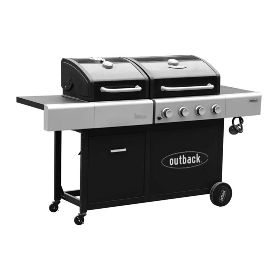
Assembly and Operating Instructions for Outback®
Dual Fuel 2 Gas & Charcoal BBQ and Dual Fuel 4 Gas & Charcoal BBQ
CS3200A
Drawings are not to scale.
Specifications subject to change
without prior notice.
For outdoor use only - do not use indoors! Not for commercial use.
Read instructions before using the appliance. Failure to follow instructions
could result in death, serious bodily injury, and/or property loss.
WARNING! Accessible parts may be very hot. Keep children and pets away!
Do not move the appliance during use.
Turn off the gas supply at the gas bottle after use.
CAUTION: Do not use spirit or petrol for lighting or re-lighting! Use only
firelighters complying to EN1860-3!
WARNING! This barbecue becomes very hot. Do not move it during operation!
Install this barbecue on a safe and even surface.
Any modification of the appliance, misuse, or failure to follow the instructions
may be dangerous and will invalidate your warranty. This does not affect your
WARNING
statutory rights.
Retain these instructions for future reference.
Leak test annually, and whenever the gas bottle is removed or replaced.
Check that the hose connections are tight and leak test each time you
reconnect the gas bottle.
For Flare-up control please refer to the 'OPERATION' section of this manual.
Do not use the barbecue in a confined and/or habitable space e.g. houses, tents,
caravans, motor homes, boats. Danger of carbon monoxide poisoning fatality.
FOR YOUR SAFETY
If you smell gas:
1.
Shut off gas to the appliance.
2.
Extinguish any open flame.
3.
Open barbecue lid or hood.
4.
If odour continues, discontinue use and
contact your local dealer.
CS4400A
FOR YOUR SAFETY
1.
Do not store or use petrol or other flammable
vapours or liquids in the vicinity of this or any
other appliance.
2.
A gas bottle not connected for use must not be
stored in the vicinity of this or any other
appliance.
0359
Advertisement
Table of Contents

Related Manuals for Outback Dual Fuel 2


Summary of Contents for Outback Dual Fuel 2
- Page 1 Assembly and Operating Instructions for Outback® Dual Fuel 2 Gas & Charcoal BBQ and Dual Fuel 4 Gas & Charcoal BBQ CS3200A CS4400A Drawings are not to scale. Specifications subject to change 0359 without prior notice. For outdoor use only - do not use indoors! Not for commercial use.
-
Page 2: Parts List
Parts List Quantity varies according to model purchased. Specifications subject to change without prior notice. For more details on hardware, please see the corresponding ‘Hardware Reference Diagram’. Dual Fuel 2 Gas & Dual Fuel 4 Gas & CODE PART Charcoal BBQ... - Page 3 Parts Diagram: Dual Fuel 2 Gas & Charcoal BBQ Quantity varies according to model purchased. Specifications subject to change without prior notice. For more details on hardware, please see the corresponding ‘Hardware Reference Diagram’.
- Page 4 Parts Diagram: Dual Fuel 4 Gas & Charcoal BBQ Quantity varies according to model purchased. Specifications subject to change without prior notice. For more details on hardware, please see the corresponding ‘Hardware Reference Diagram’.
- Page 5 Hardware Reference Diagram & List Specifications subject to change without prior notice. Dual Fuel 2 Gas & Charcoal Dual Fuel 4 Gas & Charcoal CODE PART ST4.0x10 Screw M4x8 Bolt M4 Nut M6x15 Step Bolt ...
- Page 6 Assembly IMPORTANT! TOOLS NEEDED FOR ASSEMBLY: Medium size flat blade or Phillips/Crosspoint screwdriver, adjustable spanner or metric spanner set. Remove any internal component or packaging from the barbecue body. Whilst every care is taken in the manufacture of this product, care must be taken during assembly in ...
- Page 7 Unscrew the Locknuts (C33) from both ends of the Axle (C30). Slide the axle through the corresponding holes in the right legs. Slide the Wheels (C31) over each end of the axle. Secure the wheels into place with the locknuts. Place the Wheel Hubcaps (C32) onto the outside of the wheels.
- Page 8 Attach the Front Support (C5) between the front legs using ST4.0x10 Screws (D1x4pcs) as shown. Attach the Rear Support (C4) between the rear legs using ST4.0x10 Screws (D1x4pcs) as shown.
- Page 9 Attach the Front Trim Panel (C24) to the front support and underframe using ST4.0x10 Screws (D1x4pcs) as shown. Attach the Front Panel (C25) to trolley assembly using ST4.0x10 Screws (D1x12pcs) as shown.
- Page 10 Step 1 Step 2 Attach Charcoal Bin Left Side Panel (C20) and Charcoal Bin Right Side Panel (C21) onto the Charcoal Bin Back Panel (C18) as shown. And then insert Charcoal Bin Bottom Panel (C19) into place. Make sure that each buttonhole coincide, the charcoal bin is stable. Inside Outside Attach the Charcoal Bin Front Panel (C23) onto the charcoal bin assembly using M4x8 Bolts...
- Page 11 Remove the retaining bolts from Charcoal Bin Handle (C22), then attach it onto charcoal bin front panel using the retaining bolts. Attach the charcoal bin assembly to the left front leg and front trim panel using M6x15 Step Bolts (D4x2pcs) as shown.
- Page 12 Feed one Charcoal Bin Slider (C16) through the hole of left front leg, and fix it onto charcoal bin front panel by using a M6x15 Step Bolt (D4) as shown. Repeat above process for installing the other charcoal bin slider to front trim panel and charcoal bin front panel.
- Page 13 Carefully place the Barbecue Body (B1) onto the trolley assembly and fix it by using M6x65 Bolts (D6x8pcs) as shown. Attach the Drip Tray Middle Bracket (C7) to the barbecue body using M6x15 Bolts (D5x2pcs) as shown.
- Page 14 Barbecue Body Air Vent Plate Inside Outside Attach the Air Vent Plate (B9) to the barbecue body using M6x15 Bolts (D5x4pcs), Spacers (D9x4pcs), Ø6 Washer (D7x8pcs) and M6 Nuts (D8x4pcs) as shown. Bottom View Insert the Crank Handle (B8) through the hole in the Charcoal Control Panel (B7) and screw it into the threaded socket, then secure with a R-Clip (D10) as shown.
- Page 15 Attach the Left Side Shelf Panel (C2) onto one Side Shelf (C1) using M6x15 Bolts (D5x2pcs) and M6 Nuts (D8x2pcs) as shown. Attach the left side shelf assembly to the barbecue body using ST4.0x10 Screw (D1x2pcs) and M6x15 Bolts (D5x4pcs) as shown.
- Page 16 Attach the Right Side Shelf Panel (C3) onto the other Side Shelf (C1) using M6x15 Bolts (D5x2pcs) and M6 Nuts (D8x2pcs). Attach the right side shelf assembly to the barbecue body using ST4.0x10 Screw (D1x2pcs) and M6x15 Bolts (D5x4pcs) as shown.
- Page 17 Carefully lay the Flame Tamer (B12) into the barbecue body ensuring it lies level within the body. Lay the Grill (B13) and Griddle (B14) into place. Place the Charcoal Cooking Grills (B11) above the charcoal tray on the charcoal side of the barbecue, as shown. NOTE: Ensure that the flame tamer lies directly underneath the grill.
- Page 18 CS3200A users, skip this step and proceed directly to step 26. Step 1 Step 2 Step 3 Step 4 Attach the Swing Warming Rack (A4) to the hood and barbecue body as shown. Make sure that the swing legs fix to the body of the barbecue and the shorter fixed legs go through the holes in the hood.
- Page 19 Remove the retaining bolts from Drip Tray Handle (C9), and then attach it onto the Small Drip Tray (C10) using the retaining bolts. Insert the small drip tray by sliding it underneath the charcoal barbecue body. CS4400A users, skip this step and proceed directly to step 29. Remove the retaining bolts from Drip Tray Handle (C9), and then attach it onto the Small Drip Tray (C10) using the retaining bolts.
- Page 20 CS3200A users, skip this step. Remove the retaining bolts from Drip Tray Handle (C9), and then attach it onto the Big Drip Tray (C11) using the retaining bolts. Insert the big drip tray by sliding it underneath the gas barbecue body. ASSEMBLY IS NOW COMPLETE.
-
Page 21: Leak Testing
Leak Test Diagram 1. Maximum diameter or breadth is 320mm. 2. Maximum height (regulator included) is 700mm. PROCEED TO THE NEXT PAGE FOR INSTRUCTIONS ON OPERATION AND MAINTENANCE ALL JOINTS AND CONNECTIONS MUST NOW BE LEAK TESTED BEFORE USING THE BARBECUE. -
Page 22: Gas, Regulator And Hose
Important Information a flame or spark. For use with LPG bottled gas only. A Please read these instructions carefully suitable regulator must be used for butane, before assembly and use of your barbecue. propane or mixes. LP gas bottles should never be placed ... -
Page 23: Installation
1 or local regulation, and the length should amountof briquettes to be used at any one time not exceed 1.5 metres. is 2.5kg. When placing the charcoal, never allow charcoal to be closerthan 5cm to the The regulator included with this barbecue surrounding sides of the barbecue body. - Page 24 burner is lit. closed. If burner fails to ignite after following above Raise the hinged section of charcoal grill to procedure, turn all the knobs to the off add charcoal to the charcoal tray. Turn position. Close the gas valve on the gas crank handle to adjust charcoal tray to bottle.
- Page 25 kitchen, for searing steaks, cooking eggs, etc. cooking when the charcoal is ready. When Alternatively, it can be used for heating pans or using the two handles to move the charcoal keeping food warm. cooking grill, take care to position them correctly so that the charcoal cooking grill is Roasting Hood Cooking stable.
-
Page 26: Care And Maintenance
to protect yourself from the flames. outside weather conditions or stored in damp, moist areas. If a fat fire occurs, please see the instructions given below. Never handle hot parts with unprotected hands. Fat Fires Never douse the barbecue with water when Empty and clean the drip tray of food debris after its surfaces are hot. - Page 27 It is quite normal for surface rust to be present cool dry place. on the burners. If rust appears between uses or in storage, clean with a soft brass wire brush. Cover the burners with aluminium foil in order to prevent insects or other debris from collecting in Flame Tamer burner holes.
-
Page 28: Technical Specifications
Technical Specifications NOTES: Heat Injector Burners Approval Input Size Consumption Dual Fuel 2 Gas & 0359 8.64 Butane: 628g/hr Charcoal 1.02mm 359BR665 Propane: 617g/hr BBQ / CS3200A Dual Fuel 4 Gas & 0359 12.96 Butane: 943g/hr Charcoal 0.89mm 359BR665 Propane: 926g/hr... -
Page 29: Troubleshooting
Troubleshooting Problem Possible Cause Solution Burner will not light using LP gas bottle is empty Replace with full bottle the ignition system Faulty regulator Have regulator checked or replaced Obstructions in burner Clean burner Obstructions in gas jets or gas hose Clean jets and gas hose Electrode or ignition button wire is loose Reconnect wire... - Page 30 Other parts are warranted for a period of one (1) year from the date of purchase. OUTBACK® will, within above periods, supply replacements for defective parts free of charge provided that: The product has not been used for trade, professional or hire purposes.
Need help?
Do you have a question about the Dual Fuel 2 and is the answer not in the manual?
Questions and answers