Advertisement
Quick Links
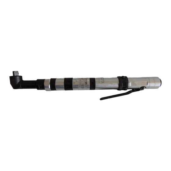
35 Series Solenoid Controlled
Nutrunners
Series:
35
Nutrunner:
Handle:
L
Lever
Transducer:
Options:
V
Vision (Lights)
VP
Vision (Lights) Positive
Solenoid Controlled:
Gear Train Designation:
5
10
7
20
NORTH AMERICA
P.O. Box 1410
Lexington, SC 29071
35
N
L
T XX
C
Operation & Service Manual
823009
-
20
XX
E
-
4
E
Ext. Housing
Angle Terminations:
K
M
15D
15˚
30D
30˚
EUROPE
Postfach 30
D-73461 Westhausen
2/01
Output Drive:
2
1/4"
3
3/8"
M
.25 Magnetic
S
Built-in Socket
(Specify Size)
T
Threaded Spindle
1
Advertisement

Related Manuals for Cleco 35 Series


Summary of Contents for Cleco 35 Series
- Page 1 Operation & Service Manual 823009 2/01 35 Series Solenoid Controlled Nutrunners T XX Series: Output Drive: Ext. Housing 1/4" Nutrunner: 3/8" .25 Magnetic Handle: Built-in Socket Lever (Specify Size) Transducer: Threaded Spindle Angle Terminations: Options: Vision (Lights) 15˚ Vision (Lights) Positive 30˚...
- Page 2 Some individuals may be susceptible to disorders of the hands and Cleco nutrunners are designed to operate on 90 psig (6.2 bar) arms when performing tasks consisting of highly repetitive motions maximum air pressure. If the tool is properly sized and applied, and/or exposure to extended vibration.
- Page 3 Safety Recommendations toms of tingling, numbness, blanching of fingers, clumsiness or Work gloves with vibration reducing liners and wrist supports are weakened grip, nocturnal pain in the hand, or any other disorder of available from some manufacturers of industrial work gloves. Tool the shoulders, arms, wrists, or fingers is advised to consult a wraps and grips are also available from a number of different physician.
- Page 4 Safety Recommendations ADDITIONAL SAFETY RECOMMENDATIONS FOR USE OF For more information on the safe use of portable air tools, see the RIGHT ANGLE DRILLS latest edition of ANSI B186.1, Safety Code for Portable Air Tools, available from the American National Standards Institute, Inc. 11 West 42nd Street, New York, NY 10036.
-
Page 5: Torque Adjustment
OPERATING INSTRUCTIONS FOR YOUR SAFETY AND THE SAFETY OF OTHERS, READ AND UNDERSTAND THE SAFETY RECOMMENDATIONS ON PAGES 2 thru 4 BEFORE OPERATING A NUTRUNNER. TORQUE ADJUSTMENT LUBRICATION The 35NLTVC nutrunner is designed to develop maxi- An automatic in-line filter-lubricator is recommended as it mum rated torque at 90 psig. - Page 6 SERVICE INSTRUCTIONS GEAR TRAIN DISASSEMBLY DISASSEMBLY —GENERAL (ALL MODELS) Single Reduction Disconnect tool from air supply. Unscrew (left hand threads) The spider should be pressed out the rear of the gear case, No. and remove the right angle head and the angle head adapter 202889.
- Page 7 SERVICE INSTRUCTIONS BACKHEAD DISASSEMBLY bearing, No. 863360, (press on the bearing's stamped end) in Unscrew and remove the inlet bushing, No.867883, for inspec- the head. Install ball bearing, No. 847846, and bearing retainer, tion and cleaning of the air inlet screen, No.869171. Replace the No.
- Page 8 SOLENOID SPECIFICATIONS 6V DC-8V DC CONTINUOUS VOLTAGE (+) SOLENOID 24V DC-36V DC FOR 15 msec MAX. 14.95ohm RESISTANCE BLACK (-) SOLENOID TOOL RECEPTACLE CABLE CONNECTORS ADJUSTMENT SCREW SOLENOID RETAINER PLUNGER PIN .015/.020 1. Solenoid plunger pin to hat dimension should be .015/.020 as shown. A new plunger pin should be spaced as shown;...
- Page 9 5/64 HEX WRENCH ADJUSTMENT SCREW SOLENOID RETAINER PLUNGER PIN SOLENOID SEAT VALVE PLUNGER 4. Using a 5/64" hex wrench, turn adjustment screw clockwise until plunger pin is pressed through hat and valve plunger is fully seated in solenoid seat. 5. Depress throttle and check tool for rated speed at 90PSI. If tool does not perform according to specifications, valve plunger may not be fully depressed.
-
Page 10: Transducer Specifications
2(Rcal) + Rbr Where Rcal = Calibration Resistor Value in ohms of the torque monitor used. The following is an example of a 35 series right angle tool and a torque monitor with a 110,000ohm calibration resistor. The values are: = 37.7 ft. - Page 11 35 & 40 SOLENOID CONTROL TOOL WIRING DIAGRAM 19 PIN CONNECTOR + EXCITATION WHITE WHITE BLACK - EXCITATION TRANDUCER BLACK GREEN + SIGNAL GREEN CAMBION CONNECTORS - SIGNAL SHIELD SHIELD + SOLENOID SOLENOID BLACK BLACK - SOLENOID CAMBION CONNECTORS YELLOW LED SIGNAL WHITE WHITE INDICATOR...
- Page 12 869034 863698 .008" "K" RIGHT 865723 .004" ANGLE HEAD 847846 863564 869864 ANGLE HEAD ADAPTER Stall Tools Only 842366 202198 202266 202200 Left Hand Threads 847853 1/4" SQ. DR. 844014 3/8" SQ. DR. 864964 202987 1/4" SQ. DR. 202986 1/4" SQ. DR. 844016 3/8"...
- Page 13 "M" RIGHT ANGLE HEAD 869034 863698 .008" 865723 .004" 847846 863564 863360 869050 ANGLE HEAD ADAPTER Stall Tools Only 882629 869048 869049 843589 847219 867642 867641 864396 842517 867643 847710 864076 869051 FLUSH SOCKET SPINDLE SIZE SPINDLE CONVERSION PART NO. KIT* PART NO. 10mm 202566-6 201102 11mm 202725-8...
- Page 14 15° ANGLE HEAD 847282 869214 869215 864751 847746 861690 1-11/16" 202127-7 869206 847747 843827 864745 1/2" 1/8" SOCKET GEAR 1-19/32" Hex Size Part No. 5/16 202129 202130 869211 869207 861690 7/16 202131 833075 847095 869222 202132 9/16 202133 10MM 202134 202128 11MM 202135...
- Page 15 30° ANGLE HEAD 847282 869214 869215 864751 847746 861691 1-9/16" 202127 869206 847747 843827 864198 7/8" 1/32" SOCKET GEAR 1-1/2" Hex Size Part No. 5/16 202129 202130 869208 869207 861691 7/16 202131 833075 847095 869222 202132 9/16 202133 10MM 202134 202128 11MM 202135...
- Page 16 GEAR TRAINS FOR 35 SOLENOID NUTRUNNERS -5 & -7 GEAR TRAINS 869254 867922 869258 203062 203143 867921 832125 202877 202888 847147 847566 203144 869256 884125 869851 867903 867902 203062 867925 844364 619017 202876 Transducerized -5, -7, -10 832128 202875 867904 869584 867906 867905...
- Page 17 MOTOR ASSEMBLIES 35 SERIES SOLENOID NUTRUNNER 203116 -5, -10, -20, (6T) 202718 203131 203117 -7, (9T) 812165 847609 869788 619377 202719 203124 PARTS LIST 35 SOLENOID NUTRUNNER MOTOR ASSEMBLIES Part No. Name of Part Qty. 202718 Front Bearing Plate 202719...
- Page 18 35NLTVC HANDLE 203357 203056 864665 203057 843518 202885 203055 Neg. Com. 832207 203349 Pos. Com. 864271 869171 844307 844060 864665 203355 203361 203360 847426 203359 843518 203356 847282 844307 203366 203036 844265 203354 844111 844306 203367 203353 203368 203365 203450 203363 203358 847426...
- Page 19 NOTES...
- Page 20 670 Industrial Drive Lexington, SC 29072 Phone: (803) 359-1200 Fax: (803) 359-2013...
Need help?
Do you have a question about the 35 Series and is the answer not in the manual?
Questions and answers