Table of Contents
Advertisement
Advertisement
Table of Contents

Related Manuals for American Panel Walk-in Monitoring System 200

Summary of Contents for American Panel Walk-in Monitoring System 200
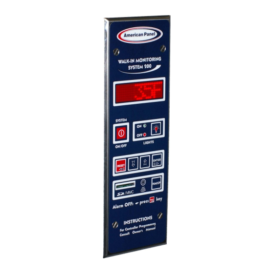
- Page 1 REV. 1/18/16 Cooler is Better! Walk-in Monitoring System 200 Used in UL Listed Door Panel Assemblies American Panel Corporation 5800 S.E. 78th Street, Ocala, Florida 34472-3412 Phone: (352) 245-7055 Fax: (352) 245-0726 E-mail: service@americanpanel.com...
- Page 2 Thank you, and congratulations on your purchase of an American Panel Walk-in Monitoring System 200. We take great pride in engineering and manufacturing each of our products. With the goal of providing the highest accuracy and quality possible, our state-of-the-art manufacturing and quality control facility enables us to continually explore new technologies so that we can provide you with the finest equipment in the industry.
-
Page 3: Table Of Contents
INTRODUCTION Index 1. INTRODUCTION AND FEATURES .............................. 4 1.1. ............................... 4 EMPERATURE ONITORING AND LARMS 1.2. ...................... 4 OOR RAME EATER EMPERATURE ONTROL AND ONITORING 1.3. HACCP ................ 5 OMPLIANT ATA OGGER AND THE OMMUNICATION ROTOCOL AND OFTWARE ... -
Page 4: Introduction And Features
INTRODUCTION 1. Introduction and Features WALK-IN MONITORING SYSTEM 200 (WIMS 200) was designed by American Panel Corporation to address multiple issues regarding walk-in units and to incorporate the functionalities of various walk-in door devices in a single, flexible, reliable, and user friendly controller. -
Page 5: Haccp Compliant Data Logger And The Pc Communication Protocol And Software
1.3. HACCP Compliant Data Logger and the PC Communication Protocol and Software American Panel Corporation understands the benefits and the importance of a complete HACCP system. That is why we designed WIMS 200 to incorporate a complete Critical Temperature Control Points monitoring system. -
Page 6: Controller
CONTROLLER 2. Controller... -
Page 7: Parameter Programming
PROGRAMMING 3. Parameter Programming All American Panel Corporation walk-in monitoring systems are programmed at the factory. The settings in this manual are considered default for WIMS 200 and were established to suit generic walk-in operating environments. However, the customer may change any of these settings as required. - Page 8 PROGRAMMING The display will show: Battery Charge Press to set the flashing value to “Y” (Yes) to enable the battery charging feature. Press when done. Next, WIMS 200 will check the battery and display the message on the right for a few seconds.
- Page 9 PROGRAMMING The display will show: Press to change the flashing value to current day. Press when done. The display will show: (12:00 AM) Press to change the flashing value to current time in one minute increments. (12:00 PM) Press and hold to change to current time in thirty minute increments.
- Page 10 PROGRAMMING The display will show: This function will set the door frame heater temperature. (Default value for coolers) Press to change the door frame heater temperature (the flashing value). Once the door frame heater temperature reaches this setting, it will stay close to (Default value for freezers) the set point, according to the factory set differential.
- Page 11 PROGRAMMING The display will show: (Default value for coolers) Set the low air alarm. To do so, press to change the flashing value representing degrees Fahrenheit. If the air temperature goes below this set point, the alarm will go off. You can set low air alarm anywhere between -30 and 50 (Default value for freezers) Press...
-
Page 12: Change The Access Code
PROGRAMMING 4. Change the Access Code To change the Access Code, you have to enter the programming mode. Follow the instructions below. Before entering the programming mode, the controller has to be in the “OFF” state. If it is not, press and hold for 5 seconds. - Page 13 PROGRAMMING After successfully re-entering the new code, the controller will briefly display the message shown in the figure on the right. The display will show: If you wish to skip parameter programming press until you get to the OFF message. To change the controller parameters, see the “Parameter Programming”...
-
Page 14: Technician Menu (Celsius/Fahrenheit Unit Selection, Temperature Probe Offset, Pc Connection Settings, Haccp Data Recording Settings)
PROGRAMMING 5. Technician Menu (Celsius/Fahrenheit Unit Selection, Temperature Probe Offset, PC Connection Settings, HACCP Data Recording Settings) Note: The technician menu includes settings that if changed could interfere with the functionality of the controller. Enter the technician menu only if it is absolutely necessary. Before entering the technician menu, the controller has to be in the “OFF”... - Page 15 PROGRAMMING The display will show: Adjust the Probe Temperature Offset Press to match the flashing value with the temperature offset calculated in Appendix 1 of this manual. OFFSET When finished, press The display will show: This setting is for factory technician only. Press to skip.
- Page 16 PROGRAMMING The controller will switch to the baud rate setting and the display will show the message on the right for a few seconds. The display will show: 38400 is a common baud rate for the most computers. Press to leave this setting unchanged.
-
Page 17: Restore The Default Settings
PROGRAMMING 6. Restore The Default Settings To restore the default settings, press and hold for ten seconds. The display will show: Press Note: After restoring the default settings, you may have to reprogram the controller. Pay special attention to the door frame heater settings. -
Page 18: Operating Wims 200
OPERATING 7. Operating WIMS 200 7.1. Turn On The Controller From the “OFF” state, turn the controller on by pressing The controller needs to stay on in order to operate. Leave it on at all times. 7.2. Read The Walk-in Air Temperature And The Current Time When on, WIMS 200 will alternate the inside air temperature display with the time display. -
Page 19: Operate The Light Switch
OPERATING 7.5. Operate The Light Switch To turn the light on, press . The green LED, next to the light button, will illuminate indicating ON status of the light. To turn the light off, press one more time. The green LED will go off and the red LED will illuminate indicating OFF status of the light. -
Page 20: Haccp Data Download Via Sd/Mmc
OPERATING 8. HACCP Data Download Via SD/MMC WIMS 200 incorporates a complete HACCP monitoring system. The integrated memory allows the controller to store data over a few days of normal operation. We believe it is a good practice to download HACCP data daily. To download HACCP data onto your computer via the SD/MMC card, follow the instructions below. - Page 21 OPERATING Column A represents the index number of the event Column B indicates the occurrence date of the event Column C indicates the occurrence time of the event Column D indicates the event type (see below for a list of the possible event types). Columns E &...
-
Page 22: Clear The Events Memory
OPERATING 8.1. Clear the Events Memory WIMS 200 memory can store 817 events. When the memory is full, it will take more time to download the data onto the SD card. Clearing the events memory on a regular basis will ensure faster data downloading onto the SD card. -
Page 23: Error Messages
OPERATING 9. Error Messages Problems beyond the routine maintenance would most likely involve the refrigeration system or the control system. Please contact the factory for assistance if this should occur. Note that the warranty would be voided if these components are serviced by other than trained technicians approved by the manufacturer. There are few error messages that could occur on WIMS 200 display: 9.1. -
Page 24: Power Failure Message
OPERATING 9.2. Power Failure Message The display will show: In the event of a power failure at the controller the display will flash the power fail message and then it will alternate with the temperature reading and the time (For 5 seconds) reading. -
Page 25: Batteries
OPERATING 10. Batteries 10.1. Connect The Battery Pack To prevent battery drainage and failure, WIMS 200 systems are shipped with the battery pack disconnected form the electronic board. Connect the battery pack to the electronic board only when the walk-in cabinet is ready for use. -
Page 26: Pc Connection Kit And Software (Optional)
PC COMMUNICATION (OPTIONAL) 11. PC Connection Kit And Software (Optional) The PC connection interface was designed to allow users to monitor and control the WIMS 200 from the convenience of an office computer. WIMS 200 can be operated and programmed from a remote PC via PC communication software (Windows 95, 98, 2000, NT, and XP). -
Page 27: More Controllers
PC COMMUNICATION (OPTIONAL) 11.3. PC Connection For Two Or More Controllers The communication protocol allows for up to 32 units to be connected at the same computer. When connecting two or more controllers to the same computer follow the check list below: ... -
Page 28: Communication Software Cpx-200
PC COMMUNICATION (OPTIONAL) 11.4. Communication Software CPX-200 The software’s interface emulates the control panel which enables the operator to control WIMS 200 from the office computer in the same way as if he would be right in front of the walk-in. The software also allows the operator to save the programmed parameters and the events memory to the PC for archival purposes. -
Page 29: Panel Operation Menu
PC COMMUNICATION (OPTIONAL) Technician Menu – This menu option is for factory use only. If it is accessed by mistake, hit once to return to “OFF” state. Load Standard Parameters – Click on this option if you want to reset the controller to the factory settings (see Chapter 6). -
Page 30: Pc Connection Troubleshooting
PC COMMUNICATION (OPTIONAL) Select Unit… - Use this option when two or more units are connected to your PC. This option allows you to select between the individual units. Download Data – Click on this option to download the events from the controller’s memory onto your 11.5. -
Page 31: Field Wiring
ELECTRICAL DIAGRAMS 12. Field Wiring Note: All field wiring must be done by a licensed electrician in compliance with the national and local electrical codes. Note: Electrician must provide seal-offs at every conduit entry on warmer side of panels. Seal inside and around the conduits where passing through panels. -
Page 32: Electrical Diagram
ELECTRICAL DIAGRAMS 13. Electrical Diagram 13.1. Wiring Diagram... - Page 33 ELECTRICAL DIAGRAMS...
- Page 34 ELECTRICAL DIAGRAMS...
- Page 35 ELECTRICAL DIAGRAMS...
-
Page 36: Pc Connection Wiring Diagram
ELECTRICAL DIAGRAMS 13.2. PC Connection Wiring Diagram... -
Page 37: Appendix 1 Air Temperature Probe Offset
Special care should be taken when adjusting the air probe temperature offset. You should never adjust the air probe temperature offset for more than 5 American Panel Corporation is not responsible for any losses such as food spoilage resulted from misusing the air probe temperature offset. - Page 38 American Panel Corporation 5800 S.E. 78th Street, Ocala, Florida 34472-3412 Phone: (352) 245-7055 Fax: (352) 245-0726 E-mail: service@americanpanel.com...
Need help?
Do you have a question about the Walk-in Monitoring System 200 and is the answer not in the manual?
Questions and answers