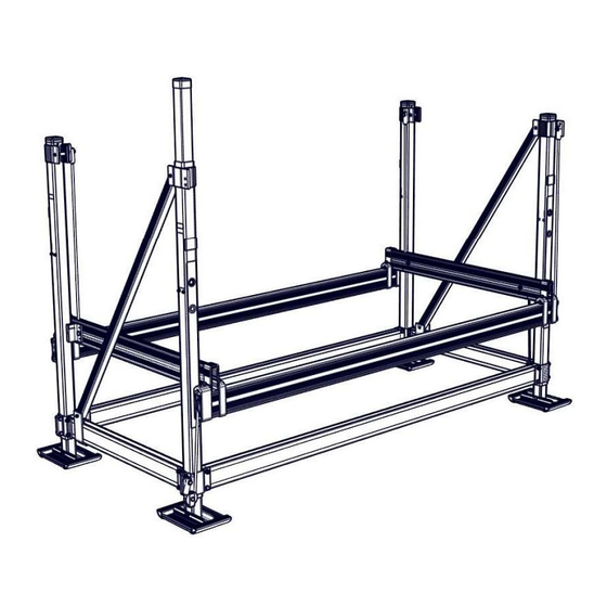
Floe V-2602 Assembly Instructions Manual
Double pwc 119” lift with patented easy level leg system
Hide thumbs
Also See for V-2602:
- Assembly instructions manual (36 pages) ,
- Assembly instructions manual (9 pages)

Related Manuals for Floe V-2602


Summary of Contents for Floe V-2602
- Page 1 FLOE V-2602 DOUBLE PWC 119” LIFT P/N 511-26080-00 WITH PATENTED EASY LEVEL LEG SYSTEM ASSEMBLY INSTRUCTIONS © Manufactured by: Floe International Inc. 48473 State Hwy. 65 McGregor, MN 55362 Instructions P/N 611-26080-00 www.floeintl.com Issued 01/14/19...
-
Page 2: Required Tools
Required Tools... - Page 3 Card Contents (511-04265-00) Step Part Numbers Descriptions Torques 001-70215-00 HHCS, 1/2-13 x 3” SS 18-8 60 ft. lbs. 001-70217-00 HHCS, 1/2-13 x 3 1/2” ss 18-8 45 ft. lbs. 001-70210-00 HHCS, 1/2-13 x 1 3/4” ss 18-8 45 ft. lbs. 001-70219-00 HHCS, 1/2-13 x 4”...
- Page 4 Warnings IMPORTANT NOTE: DO NOT USE IMPACT WRENCH WHEN ADJUSTING THE EASY LEVEL LEGS Tips Torque nuts to specification, not bolts. Place parts and fasteners in designated locations prior to each step. Before tightening fasteners to specified torque, ensure that the lift is square. ...
- Page 5 Pre-Assembly Prep Lift Dimensions Length: 66” Width: 134 3/8” Height: 104” Work Space Level work space Allow space to organize parts Material Blocking may be anything 10”-15” in height. (5-gallon bucket, jack stands, blocks, saw horses) 4 (2 for each side) Purpose Blocking used to support lift during assembly steps 1 and 2...
- Page 6 Contents for Step 1 NOTE (2) ½” Nuts and (2) ½” Washers are used in Step 5-A to attach (24) 1/2” Alum. Nylock Nuts lifting cables to (2) (2) 1/2 x 4” ss Bolts ½” x 4” Bolts (8) 1/2 x 3 1/2” ss Bolts NOTE ALL FASTENERS IN (6) 1/2 x 3”...
- Page 7 Assembly for Step 1 NOTE (2) ½” Nylock Nuts and (2) ½” Washers ARE NOT used for (2) ½” x 4” Bolts on corners A and D until Step 6-D.
- Page 9 FRONT/REAR IMPORTANT NOTE: FRAME BEAMS MUST BE IN THIS ORIENTATION BEFORE CONTINUING. FRONT/REAR...
- Page 10 Contents for Step 2 (4) 1/2” Alum. Nylock Nuts (4) 1/2 x 3 3/4” ss Bolts Torque to 25 ft. lbs.
- Page 11 Assembly of Step 2 NOTE CARRIDGE BOLT HEADS MUST FACE INSIDE OF LIFT. NUTS MUST FACE OUTSIDE OF LIFT. NOTE WATER DEPTH STICKERS MUST FACE OUT ON FRONT AND REAR OF LIFT.
- Page 12 NOTE BUTT THE CORNER POST TAB UP TO THE FRAME BEAM CLAMP.
- Page 13 NOTE THIS TORQUE SPECIFICATION APPLIES TO THE 3” BOLT (ABOVE 4” BOLT) BOLTS ON POST A AND POST D ONLY.
- Page 14 Contents for Step 3 (4) 3/8 x 3 1/2” SS Bolts Torque to 35 ft. lbs. (4) 3/8 x 3” SS Bolts Torque to 35 ft. lbs. (8) 3/8” Alum. Nylock Nuts...
- Page 15 Assembly of Step 3...
- Page 17 Contents for Step 4 (8) 1/2” Alum. Nuts (8) 1/2 x 1 1/2” ss Bolts Torque to 45 ft. lbs.
- Page 18 Assembly of Step 4 NOTE LIFTING CABLE IN UPWARD DIRECTION IS PLACED ON POST B AND POST C. NOTE LIFTING CABLE IN DOWNWARD DIRECTION IS PLACED ON POST A AND POST D.
- Page 19 NOTE SURFACES MUST BE FLUSH.
- Page 21 Contents for Step 5 NOTE Recall (2) ½” Nylock Nuts and (2) ½” Washers from Step 1. Torque to 60 Ft. Lbs. (5) 1/2 x 2” ss Bolts Torque to 45 ft. lbs. (5) 1/2” Alum. Nylock Nuts...
- Page 22 Assembly of Step 5 NOTE Recall (2) ½” Nylock Nuts and (2) ½” Washers from Step 1.
- Page 24 V-2602 LIFT LIFT P/N 511-26080-00 PART NO. QTY. DESCRIPTION PART NO. QTY. DESCRIPTION 002-00049-01 POST, CORNER .090" WALL - 74" 001-74402-00 CARRIAGE BOLT, 5/16-18 x 3 1/2" SS 18-8 002-00053-00 BEAM, LIFT FRAME .09 - 48" 001-71024-00 FLAT WASHER, 5/8" x 1.25" x .060 SS 002-04314-00 BRACKET, LEVEL LEG - 2.563"...
- Page 25 V-2602 Frame Exploded View A LIFT P/N 511-26080-00...
- Page 26 V-2602 Frame Exploded View B LIFT P/N 511-26080-00...
- Page 27 V-2602Frame Exploded View C LIFT P/N 511-26080-00...
Need help?
Do you have a question about the V-2602 and is the answer not in the manual?
Questions and answers