Advertisement
FLOE 24 vOLt vSD DrivE
3800, 5000, 6000, 6500 & 8000# LiFtS
P/Ns 511-38500-00, 511-60020-00, 511-80020-00
ASSEMBLY iNStrUCtiONS
TOOLS REQUIRED:
(2)
3/4" socket or wrench for 1/2"
nuts and bolts
(1)
9/16" socket or wrench for 3/8"
nuts and bolts
(1)
Flat tip screwdriver
(1)
Torque wrench
INSTRUCTION P/N: 611-50025-00
ISSUE DATE: 9/11/13
REVISED: 9/28/17
Manufactured By:
Floe International, Inc.
48473 State Hwy. 65
McGregor, MN 55760
Advertisement
Table of Contents

Related Manuals for Floe 3800


Summary of Contents for Floe 3800
- Page 1 FLOE 24 vOLt vSD DrivE 3800, 5000, 6000, 6500 & 8000# LiFtS P/Ns 511-38500-00, 511-60020-00, 511-80020-00 ASSEMBLY iNStrUCtiONS TOOLS REQUIRED: 3/4” socket or wrench for 1/2” nuts and bolts 9/16” socket or wrench for 3/8” nuts and bolts Flat tip screwdriver...
- Page 2 Parts List Two – Battery Box w/Volt Meter, Cover & Strap, 111-00461-00 One – Packet of Anti-Seize One – VSD Tool Kit One – Tool Kit Pouch, 007-03980-00 One – 3/8” Drive Socket Adapter, 007-03981-00 One – Grease Gun Adapter, 007-03982-00 One –...
- Page 3 Page 3 of 8...
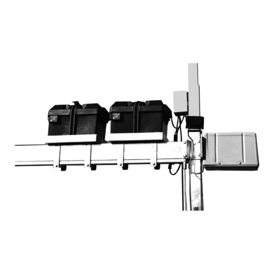
- Page 4 steP 1 - - - - - - - - - - - - - - - - With the lift frame assembly done the VSD Drive Train and electronics can now be installed. Apply a generous amount of anti-seize to the inside of the rigid coupler (Fig. 1A). Then attach Attach using four the “VSD Power Unit”...
- Page 5 steP 3 - - - - - - - - - - - - - - - - - - - - - Clean and adhere the dual lock 5-1/4” down from the top of the corner post. (Fig. 3A) Attach the Advanced Fig.
- Page 6 steP 4 - - - - - - - - - - - - - - - - - - - - - - - - - - - Connect the two remaining wires coming out of the Advanced Switch Control (ASC) box to the batteries. The two wires on the Advanced Switch Control have ring connectors.
- Page 7 steP 5 - - - - - - - - - - - - - - - - - Fig. 5A Plug 4 connector wired remote into the corresponding lead of the Advanced System Control box. Note: The wired remote lead is identified by the blue wire tie next to the base of the plug on the ASC as shown.
- Page 8 steP 6 - - - - - - - - - - - - - Secure all loose wires and the wire from the wired remote to the lift structure by cutting off pieces of the included double sided Velcro. The best way to secure the wired remote is to go up from the Advanced Switch Control and attach the wire to the inside of the canopy frame if you have one.
Need help?
Do you have a question about the 3800 and is the answer not in the manual?
Questions and answers