
Related Manuals for GoMax Electronics MX-1004PF


Summary of Contents for GoMax Electronics MX-1004PF
- Page 1 Professional Quad-View Video Processor User Manual rev: 140516 Made in Taiwan...
- Page 2 fety Noti The MX-10 as been te ested for co onformity to 004PF Prof fessional Q Quad-View w Video Pr rocessor safety regu ulations and d requireme ents, and ha as been ce ertified for in nternational use. Howe ever, like al electronic e equipments s, the MX-10...
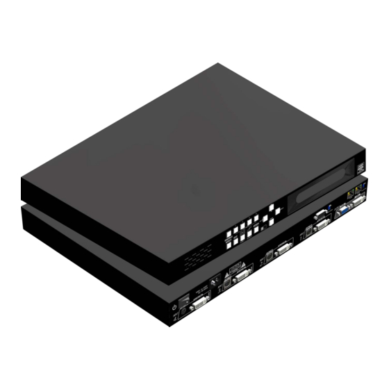
- Page 3 INTRODUCTION The MX-1004PF Professional Quad-View Video Processor is an advanced video processor for multimedia presentations. It is an ideal solution for applications where up to four video signals must be displayed on a single display. It supports up to 16 video inputs, of which four can be outputted simultane- ously with the desired display layout through software control.
-
Page 4: Package Contents
● Control protocol available for customer proprietary design ● 1U size. PACKAGE CONTENTS ● ● 1x MX-1004PF 4x DVI to DVI & VGA breakout cable ● ● 4x VGA to component breakout cable 4x S-Vedio & Composite breakout cable ●... -
Page 5: Specifications
SPECIFICATIONS Model Name MX-1004PF Technical Role of usage Multiplexer / video processor Dual output support Yes [DVI & VGA] Background video input HDCP compliance DVI/HDMI[Single-link 4.95Gbps] VGA[165MHz] Video bandwidth Component [30MHz] Composite [13.5MHz] S-Video [13.5MHz] Video support 480i / 480p / 720p / 1080i / 1080p60 / 1920x1200@75 / 1600x1200@60... -
Page 6: Panel Descriptions
(DVI or VGA), composite, and component video sources respectively. You can pick up four of the ten inputs and then display four of them simultaneously on the same screen. Figure 2 shows the rear panel connectors of a MX-1004PF and Table 1 illustrates how you can connect video devices and display to the MX-1004PF. - Page 7 NTRO OL P PANE EL A PAP Full Sc creen Functi ion key: Lay yout 2 Input Selec Functi ion key: N/A Function ke ey: Input Sig gnal Infrare ed Sensor Function ke ey: Setting Naviga ation Function ke ey: Layout 1 electing PIP P Window Ar rrangement...
- Page 8 [Quad Windows in crisscross + 3 user-defined custom To cancel the operation, press [ LAYOUT 2] again select a type by pressing according button while VFD display prompts B_top : press UP B_btm : press DOWN B_left : press LEFT B_right : press RIGHT...
-
Page 9: Ir Remote Control
IR REMOTE CONTROL MX-1004PF ships with a compact remote control that allows for direct access to most commands used to control the video processor. IR Remote Button Define Power Button Power ON/OFF the device Cross-Layout Set PAP layout to default layout (cross type ) -
Page 10: Hardware Installation
6. Connect a device equipped with component video output (YPbPr such as DVD player or camera) to the 3-RCA jack of the VYPBA01. 7. Connect a device equipped with VGA output (such as laptop) to the VGA connector of MX-1004PF. 8. Connect a device equipped with composite video output to composite input of the MX-1004PF. -
Page 11: Operation Software
COM port and the MX-1004PF and switched on the MX-1004PF with green LED light. Instruction of Software Connection 1. Power up the MX-1004PF and you can see VFD on the front panel blink. Make sure the serial port mode is right for your setting. RS-232 mode: , RS-485 mode: 2. - Page 12 Definitions of Menu Buttons and Icons The software has following menu options available: Fast Linkage This button will update software GUI for device state Output Resolution Supported Mode Resolution Supported Mode Resolution HDTV 720p 1280x720 @ 60Hz VESA 1280x768 @ 60Hz HDTV 1080p 1920x1080 @ 60Hz VESA...
- Page 13 Background Setting MX-1004PF offers the video background to make this advanced unit actually working like 5 channel video mixer! The default background video must work as full screen! Users can choose between color and video background through the following control window. Click on this button will show the dialog for output resolution, background color and background channel setting.
- Page 14 Display / Layout Mode Set signal channel full screen or all channel Notice that the input sources will not be changed in Software. Default Layouts There are 5 pre-configured layouts available from Control Software, IR Remote Control or Front Panel Buttons. Panel Cross Panel Right –...
- Page 15 Panel Cross Panel Right – Type Panel Left – Type...
- Page 16 Panel Top – Type Panel Bottom – Type Input Signal which is selected at “Focus Input” will be displayed as Main Video Sources. Focus Input Select which Input Source should stay in focus when “Layouts” are selected Save and Set Custom Layouts Save up to 8 Custom Layouts and Set them using Control Software, Front Panel or IR Remote Control.
- Page 17 Layout Control Size Set layout control size in Software by percent. If you enable Fixed Stretch, Aspect Ratios are kept with each Input layout is changed. Layout Control Create different Layouts by Drag and Drop. You can use “Fixed Aspect Ratio” as described above to retain Aspect Ratio of source image.
- Page 18 [Size and Position] Select on “Size / Pos” Channel Windows Visible: You may uncheck “Channel Window Visible” if you decide to not show this Windows on screen Blend: Change the value of Blending from 100% to 0%. This will allow you to overlay an Input Source on other.
-
Page 19: Software Configuration
[Color Setting] Various options change Brightness, Contrast, Saturation, Hue, Red, Green and Blue are available on each “Input Source” [Color Balance and Auto Configure] You may adjust Color Balance and Auto Configure them by selecting these options SOFTWARE CONFIGURATION Follow these steps to select right Output Resolution and Input Signal •... - Page 20 THE FIRMWARE UPDATE PROCESS If your firmware is not newest, the control will display the dialog after link the device. Please “Execute” botton to firmware update Control Mdoule Update: Please follow the step to update the Control Module...
- Page 21 Please click the “Update” button to update Contorl Module The process bar will run after the device power cycle.If it is not working, please check the DIP switch is correct(In the step 1)
- Page 22 Please make sure the DIP Switch is feedback to right state. Please check the check box than click the “Next” button to update Mixer Module Select the modules that you want update mixer units, than click “Update” button to update Mixer Module.
- Page 23 When the update is finish, please check the update state is “Done”. Click the “Next” button Click “Factory Reset” to configure the device to correct state.
-
Page 24: Troubleshooting
TROUBLESHOOTING Problem Recommendations Check if you correctly and firmly plug AC power core into MX-1004PF If you are recovering from power outage, accidentally unplug the power No power core or other power surge conditions, leave the device off for a while and then power it on again. -
Page 25: Limited Warranty
SELLER will NOT be liable for direct, indirect, incidental, special, or consequential damages resulting from any defect or omission in this manual, even if advised of the possibility of such damages. Also, the technical information contained herein regarding the MX-1004PF features and specifications is subject to change without further notice. -
Page 26: Appendix - Supported Resolution
APPENDIX – SUPPORTED RESOLUTION [ DVI-x / YPbPr-x / VGA-x (x = 1~4)] Socket Supported Mode Resolution Supported Mode Resolution NTSC/480i/525i 720x240 @60Hz VESA 800x600 @75Hz PAL/576i/625i 720x288 @50Hz VESA 800x600 @85Hz 480p/525p 720x483 @60Hz 832x624 @75Hz 480p (16:9) 960x483 @60Hz VESA 1024x768 @60Hz 576p/625p... - Page 27 [DVI-OUT] socket Supported Mode Resolution Supported Mode Resolution (HDTV) 720p 1280x720 @50Hz VESA 1366x768 @60Hz (HDTV) 720p 1280x720 @60Hz VESA 1400x1050 @60Hz (HDTV) 1080p 1920x1080 @60Hz VESA 1400x1050 @50Hz VESA 640x480 @60Hz VESA 1152x864 @75Hz VESA 800x600 @60Hz VESA 1600x1200 @60Hz VESA 1024x768 @60Hz VESA...
Need help?
Do you have a question about the MX-1004PF and is the answer not in the manual?
Questions and answers