Siemens SINAMICS S120 Equipment Manual
Chassis power units
Hide thumbs
Also See for SINAMICS S120:
- Function manual (1094 pages) ,
- Diagnostic manual (947 pages) ,
- Manual (848 pages)
Table of Contents
Advertisement
Quick Links
Advertisement
Table of Contents

Related Manuals for Siemens SINAMICS S120


Summary of Contents for Siemens SINAMICS S120
- Page 1 SINAMICS S120 Chassis power units Equipment Manual · 10/2008 SINAMICS...
- Page 3 Preface System overview Line-side power components SINAMICS Line Modules S120 Chassis power units Motor Modules DC link components Manual Motor-side power components Cabinet design and EMC Maintenance and Servicing List of abbreviations (GH3), 10/2008 6SL3097-2AE00-0BP3...
- Page 4 Note the following: WARNING Siemens products may only be used for the applications described in the catalog and in the relevant technical documentation. If products and components from other manufacturers are used, these must be recommended or approved by Siemens. Proper transport, storage, installation, assembly, commissioning, operation and maintenance are required to ensure that the products operate safely and without any problems.
-
Page 5: Preface
● Documentation online Information on DoconCD and direct access to the publications in DoconWeb. ● Assemble documentation individually on the basis of Siemens content with the My Documentation Manager (MDM), see http://www.siemens.com/mdm The My Documentation Manager offers you a range of features for creating your own machine documentation. - Page 6 European and African time zone Telephone +49 180 5050 - 222 +49 180 5050 - 223 €0.14/min. from German landlines, mobile phone prices may differ Internet http://www.siemens.de/automation/support-request America time zone Telephone +1 423 262 2522 +1 423 262 2200 E-mail mailto:techsupport.sea@siemens.com...
- Page 7 ● on the Internet: http://support.automation.siemens.com under the Product/Order No. 15257461 ● from the relevant regional office of the I DT MC Business Unit of Siemens AG. The EC Declaration of Conformity for the Low Voltage Directive can be found/obtained ● on the Internet: http://support.automation.siemens.com...
- Page 8 Preface Safety information DANGER Commissioning must not start until you have ensured that the machine in which the components described here are to be installed complies with Directive 98/37/EC. SINAMICS S equipment must only be commissioned by suitably qualified personnel. The personnel must take into account the information provided in the technical customer documentation for the product, and be familiar with and follow the specified danger and warning notices.
- Page 9 Preface Note When operated in dry operating areas, SINAMICS equipment with AC motors conforms to Low-Voltage Directive 2006/95/EC. Note In the configuration specified in the corresponding EC Declaration of Conformity regarding EMC requirements and when the EMC installation guideline (order no. 6FC5297-0AD30-0*P2) is observed, SINAMICS devices conform to EMC Directive 89/336/EEC and 2004/108/EC.
- Page 10 Preface Residual risks of power drive systems When carrying out a risk assessment of the machine/plant in accordance with the EU Machinery Directive, the machine manufacturer/plant operator must consider the following residual risks associated with the control and drive components of a power drive system (PDS).
- Page 11 Preface WARNING Electromagnetic fields "electro smog" Electromagnetic fields are generated by the operation of electrical power engineering installations such as transformers, converters or motors. Electromagnetic fields can interfere with electronic devices, which could cause them to malfunction. For example, the operation of heart pacemakers can be impaired, potentially leading to damage to a person's health or even death.
- Page 12 Preface Chassis power units Manual, (GH3), 10/2008, 6SL3097-2AE00-0BP3...
-
Page 13: Table Of Contents
Correction factors for increased ambient temperatures and installation altitudes.......29 Basic structure of a drive system with SINAMICS S120 .............32 1.5.1 Structure of a drive system with SINAMICS S120 and regulated infeed........32 1.5.2 Structure of a drive system with SINAMICS S120 and unregulated infeed/regenerative feedback............................33... - Page 14 Table of contents Line Modules ............................71 Introduction ..........................71 Basic Line Modules ........................72 3.2.1 Description ..........................72 3.2.2 Safety information ........................73 3.2.3 Interface description........................74 3.2.3.1 Overview ............................. 74 3.2.3.2 Connection example ........................76 3.2.3.3 Line/load connection ........................77 3.2.3.4 X9 terminal strip ..........................
- Page 15 Table of contents 4.3.1 Overview ............................142 4.3.2 Connection example ........................150 4.3.3 DC link/motor connection......................152 4.3.4 X9 terminal strip .........................153 4.3.5 DCPS, DCNS connection for a dv/dt filter .................153 4.3.6 X41 EP terminal / temperature sensor connection ..............153 4.3.7 X42 terminal strip ........................155 4.3.8 X46 Brake control and monitoring .....................155 4.3.9...
- Page 16 Table of contents Motor-side power components....................... 211 Sine-wave filter.......................... 211 6.1.1 Description ..........................211 6.1.2 Safety information ........................212 6.1.3 Dimension drawing........................213 6.1.4 Technical specifications ......................214 Motor reactors ........................... 215 6.2.1 Description ..........................215 6.2.2 Safety information ........................215 6.2.3 Dimension drawing........................
- Page 17 Table of contents 8.4.13 Replacing the Control Interface Board, Smart Line Module, Active Line Module, and Motor Module, frame size GX ....................290 8.4.14 Replacing the Control Interface Module, Motor Module, frame size HX ........292 8.4.15 Replacing the Control Interface Board, Smart Line Module, Active Line Module, and Motor Module, frame size HX ....................294 8.4.16 Replacing the Control Interface Module, Motor Module, frame size JX ........296...
- Page 18 Table of contents Chassis power units Manual, (GH3), 10/2008, 6SL3097-2AE00-0BP3...
-
Page 19: System Overview
The SINAMICS range of drives Field of application SINAMICS is the new range of converters from Siemens designed for industrial mechanical and plant engineering applications. SINAMICS offers solutions for all drive tasks: ● Simple pump and fan applications in the process industry ●... - Page 20 The different SINAMICS versions can be easily combined with each other. SINAMICS is part of the Siemens "Totally Integrated Automation" concept. Integrated SINAMICS systems covering configuration, data storage, and communication at automation level ensure low-maintenance solutions with the SIMATIC, SIMOTION, and SINUMERIK control systems.
-
Page 21: Sinamics S120 Drive System
SIZER, a high-performance engineering tool, makes it easier to choose and determine the optimum drive configuration. SINAMICS S120 is enhanced by a wide range of motors. Whether synchronous or induction, all motor types are supported by SINAMICS S120. - Page 22 SINAMICS S120 takes a different approach. A central Control Unit controls the drive for all connected axes and also establishes the technological links between the drives and/or axes.
- Page 23 1.2 SINAMICS S120 drive system DRIVE-CLiQ – the digital interface between all components All SINAMICS S120 components, including the motors and encoders, are interconnected by a shared serial interface called DRIVE-CLiQ. The standardized cables and connectors reduce the variety of different parts and cut storage costs.
- Page 24 ● Additional system components that enhance functionality and offer different interfaces for encoders and process signals. SINAMICS S120 components were developed for installation in cabinets. They have the following features and characteristics: ● Easy to handle, simple installation and wiring ●...
-
Page 25: Technical Specifications
1.3 Technical specifications Technical specifications Technical specifications Unless specified otherwise, the following technical specifications are valid for all the following components of the SINAMICS S120 drive system. Table 1- 1 General technical specifications Electrical data 3-ph. 380 V AC -10% (-15% < 1 min) to 3-ph. 480 V AC +10% Line connection voltage •... - Page 26 System overview 1.3 Technical specifications Permissible ambient and coolant 0 °C to +55 °C up to 2000 m above sea level temperature (air) during operation for DC link and motor-side power components Active Interface Modules, Basic Line Modules, Smart Line Modules, Active Cooling method according to •...
-
Page 27: Derating Factors
System overview 1.4 Derating factors Derating factors 1.4.1 Derating factors as a function of installation altitude and ambient temperature Figure 1-4 Current correction factor K as a function of the cooling air temperature Note A current correction factor of K >... - Page 28 System overview 1.4 Derating factors Figure 1-5 Current correction factor K as a function of the installation altitude At installation altitudes above 2000 m (6562 ft), the line voltage must not exceed certain limits to ensure that surge voltages can be insulated in accordance with EN 60664-1 for surge voltage category III.
-
Page 29: Correction Factors For Increased Ambient Temperatures And Installation Altitudes
System overview 1.4 Derating factors Figure 1-6 Voltage correction factor K as a function of the installation altitude Note The dashed line represents a theoretical characteristic of the correction factor. The devices have an undervoltage threshold, which leads to shutdown when the voltage drops below it. Consequently, the input voltage range that is actually usable has a lower limit. - Page 30 System overview 1.4 Derating factors Example 1 A drive system comprising Line and Motor Modules is to be operated at an altitude of 2500 m at a maximum ambient temperature of 30 °C. Since the ambient temperature is below 40 °C, a compensation calculation (installation altitude/ambient temperature) can be carried out.
- Page 31 System overview 1.4 Derating factors Example 2 When a drive line-up is configured, a Motor Module with the order number 6SL3320-1TE32-1AA0 is selected. The drive line-up is to be operated at an altitude of 3000 m where ambient temperatures could reach 35 °C as a result of the installation conditions.
-
Page 32: Basic Structure Of A Drive System With Sinamics S120
Basic structure of a drive system with SINAMICS S120 1.5.1 Structure of a drive system with SINAMICS S120 and regulated infeed Figure 1-7 Basic structure of a drive system with SINAMICS S120 and regulated infeed Chassis power units Manual, (GH3), 10/2008, 6SL3097-2AE00-0BP3... -
Page 33: Structure Of A Drive System With Sinamics S120 And Unregulated Infeed/Regenerative Feedback
1.5 Basic structure of a drive system with SINAMICS S120 1.5.2 Structure of a drive system with SINAMICS S120 and unregulated infeed/regenerative feedback Figure 1-8 Basic structure of a drive system with SINAMICS S120 and unregulated infeed/regenerative feedback Chassis power units Manual, (GH3), 10/2008, 6SL3097-2AE00-0BP3... -
Page 34: Structure Of A Drive System With Sinamics S120 And Unregulated Infeed
1.5 Basic structure of a drive system with SINAMICS S120 1.5.3 Structure of a drive system with SINAMICS S120 and unregulated infeed Figure 1-9 Basic structure of a drive system with SINAMICS S120 and unregulated infeed Chassis power units Manual, (GH3), 10/2008, 6SL3097-2AE00-0BP3... -
Page 35: Line-Side Power Components
Line-side power components General Line-side power components are used to protect the connected components against transient or continuous overvoltages and ensure that prescribed limit values are adhered to. Chassis power units Manual, (GH3), 10/2008, 6SL3097-2AE00-0BP3... -
Page 36: Line Filters For Basic Line Modules
Line-side power components 2.2 Line filters for Basic Line Modules Line filters for Basic Line Modules 2.2.1 Description In conjunction with line reactors and a systematic plant configuration, line filters limit the conducted interference emitted by the power modules at the installation location to permissible values for industry. -
Page 37: Dimension Drawing
Line-side power components 2.2 Line filters for Basic Line Modules CAUTION Using line filters not approved by SIEMENS for SINAMICS can lead to line-side harmonics that can interfere with or damage other loads powered from the network. 2.2.3 Dimension drawing... - Page 38 Line-side power components 2.2 Line filters for Basic Line Modules Table 2- 1 Dimensions of line filters for Basic Line Modules (all data in mm) 6SL3000- 0BE34-4AA0 0BE36-0AA0 0BE41-2AA0 0BE41-6AA0 0BG34-4AA0 0BG36-0AA0 0BG41-2AA0 – – – 78.2 Lengths n1 and n2 correspond to the distance between holes Chassis power units Manual, (GH3), 10/2008, 6SL3097-2AE00-0BP3...
-
Page 39: Technical Specifications
Line-side power components 2.2 Line filters for Basic Line Modules 2.2.4 Technical specifications Table 2- 2 Technical specifications of line filters for Basic Line Modules, 380 V – 480 V 3 AC Order number 6SL3000- 0BE34-4AA0 0BE36-0AA0 0BE41-2AA0 0BE41-2AA0 0BE41-6AA0 Suitable for 6SL3330- 1TE34-2AA0... -
Page 40: Line Reactors For Basic Line Modules
The connecting cables to the Line Module must be kept as short as possible (max. 5 m). CAUTION When using line reactors that have not been approved by SIEMENS for SINAMICS, the following can occur: • The Basic Line Modules may become damaged/faulty. -
Page 41: Dimension Drawing
Line-side power components 2.3 Line reactors for Basic Line Modules 2.3.3 Dimension drawing Figure 2-2 Dimension drawing of line reactors for Basic Line Modules Chassis power units Manual, (GH3), 10/2008, 6SL3097-2AE00-0BP3... - Page 42 Line-side power components 2.3 Line reactors for Basic Line Modules Table 2- 4 Dimensions of line reactors for Basic Line Modules, 380 V – 480 V 3 AC (all values in mm) 6SL3000- 0CE35-1AA0 0CE37-7AA0 0CE41-0AA0 0CE41-5AA0 152.5 212.5 212.5 211.5 Lengths n1 and n2 correspond to the distance between holes Table 2- 5...
-
Page 43: Technical Specifications
Line-side power components 2.3 Line reactors for Basic Line Modules 2.3.4 Technical specifications Table 2- 6 Technical specifications of line reactors for Basic Line Modules, 380 V – 480 V 3 AC Order number 6SL3000- 0CE35-1AA0 0CE35-1AA0 0CE37-7AA0 0CE41-0AA0 0CE41-5AA0 Suitable for 6SL3330- 1TE34-2AA0... -
Page 44: Line Reactors For Smart Line Modules
The connecting cables to the Line Module must be kept as short as possible (max. 5 m). CAUTION When using line reactors that have not been approved by SIEMENS for SINAMICS, the following can occur: • The Smart Line Modules may become damaged/faulty. -
Page 45: Dimension Drawing
Line-side power components 2.4 Line reactors for Smart Line Modules 2.4.3 Dimension drawing Line reactor 6SL3000-0EE36-2AA0 Figure 2-3 Dimension drawing of line reactor 6SL3000-0EE36-2AA0 Table 2- 8 Dimensions (all dimensions in mm) – – Lengths D and E correspond to the distance between holes Chassis power units Manual, (GH3), 10/2008, 6SL3097-2AE00-0BP3... - Page 46 Line-side power components 2.4 Line reactors for Smart Line Modules Line reactor 6SL3000-0EE38-8AA0 Figure 2-4 Dimension drawing of line reactor 6SL3000-0EE38-8AA0, all dimensions in mm Chassis power units Manual, (GH3), 10/2008, 6SL3097-2AE00-0BP3...
- Page 47 Line-side power components 2.4 Line reactors for Smart Line Modules Line reactor 6SL3000-0EE41-4AA0 Figure 2-5 Dimension drawing of line reactor 6SL3000-0EE41-4AA0 Table 2- 9 Dimensions (all dimensions in mm) 80.5 130.5 Lengths D and E correspond to the distance between holes Note The crane lifting eyes can be removed after installation.
- Page 48 Line-side power components 2.4 Line reactors for Smart Line Modules Line reactor 6SL3000-0EH34-7AA0 Figure 2-6 Dimension drawing of line reactor 6SL3000-0EH34-7AA0 Table 2- 10 Dimensions (all dimensions in mm) 16.5 – – Lengths D and E correspond to the distance between holes Chassis power units Manual, (GH3), 10/2008, 6SL3097-2AE00-0BP3...
- Page 49 Line-side power components 2.4 Line reactors for Smart Line Modules Line reactor 6SL3000-0EH37-6AA0 Figure 2-7 Dimension drawing of line reactor 6SL3000-0EE37-6AA0, all dimensions in mm Note The crane lifting eyes can be removed after installation. Chassis power units Manual, (GH3), 10/2008, 6SL3097-2AE00-0BP3...
- Page 50 Line-side power components 2.4 Line reactors for Smart Line Modules Line reactor 6SL3000-0EE41-4AA0 Figure 2-8 Dimension drawing of line reactor 6SL3000-0EH41-4AA0 Table 2- 11 Dimensions (all dimensions in mm) 88.5 79.5 236.5 139.5 149.5 108.5 Lengths D and E correspond to the distance between holes Note The crane lifting eyes can be removed after installation.
-
Page 51: Technical Specifications
Line-side power components 2.4 Line reactors for Smart Line Modules 2.4.4 Technical specifications Table 2- 12 Technical specifications of line reactors for Smart Line Modules, 380 V – 480 V 3 AC Order number 6SL3000- 0EE36-2AA0 0EE36-2AA0 0EE38-8AA0 0EE41-4AA0 0EE41-4AA0 Suitable for 6SL3330- 6TE35-5AA0... -
Page 52: Active Interface Modules
Line-side power components 2.5 Active Interface Modules Active Interface Modules 2.5.1 Description Active Interface Modules are used in conjunction with the Active Line Modules in chassis format. The Active Interface Modules contain a Clean Power Filter with basic RI suppression, the pre-charging circuit for the Active Line Module, the line voltage sensing circuit and monitoring sensors. -
Page 53: Safety Information
Line-side power components 2.5 Active Interface Modules 2.5.2 Safety information CAUTION The DC link discharge time hazard warning must be affixed to the component in the relevant local language. NOTICE The cooling clearances above, below, and in front of the component, which are specified in the dimension drawings, must be observed. -
Page 54: Interface Description
Line-side power components 2.5 Active Interface Modules 2.5.3 Interface description 2.5.3.1 Overview Figure 2-9 Interface overview in the Active Interface Module, frame size FI Chassis power units Manual, (GH3), 10/2008, 6SL3097-2AE00-0BP3... - Page 55 Line-side power components 2.5 Active Interface Modules Figure 2-10 Interface overview in the Active Interface Module, frame size GI Chassis power units Manual, (GH3), 10/2008, 6SL3097-2AE00-0BP3...
- Page 56 Line-side power components 2.5 Active Interface Modules Figure 2-11 Interface overview in the Active Interface Module, frame size HI Chassis power units Manual, (GH3), 10/2008, 6SL3097-2AE00-0BP3...
- Page 57 Line-side power components 2.5 Active Interface Modules Figure 2-12 Interface overview in the Active Interface Module, frame size JI Chassis power units Manual, (GH3), 10/2008, 6SL3097-2AE00-0BP3...
-
Page 58: Connection Example
Line-side power components 2.5 Active Interface Modules 2.5.3.2 Connection example Figure 2-13 Connection example Active Interface Module, frame sizes FI / GI Chassis power units Manual, (GH3), 10/2008, 6SL3097-2AE00-0BP3... -
Page 59: X1, X2 Line/Load Connection
Line-side power components 2.5 Active Interface Modules Figure 2-14 Connection example Active Interface Module, frame sizes HI / JI 2.5.3.3 X1, X2 line/load connection Table 2- 15 Connections for the Active Interface Module Terminals Designations X1: L1, L2, L3 Voltage: X2: U2, V2, W2 3-ph. -
Page 60: Drive-Cliq Interface X500
Line-side power components 2.5 Active Interface Modules 2.5.3.4 DRIVE-CLiQ interface X500 Table 2- 16 DRIVE-CLiQ interface X500 Signal name Technical specifications Transmit data + Transmit data - Receive data + Reserved, do not use Reserved, do not use Receive data - Reserved, do not use Reserved, do not use + (24 V) -
Page 61: Meaning Of The Led On The Voltage Sensing Module (Vsm) In The Active Interface Module
Line-side power components 2.5 Active Interface Modules CAUTION Active Interface Modules of frame sizes HI and JI require a signal on terminal X609:11 and 12 to control the fans. If this signal is not present during operation, the fans do not rotate and the module is shut down on overtemperature. -
Page 62: Dimension Drawing
Line-side power components 2.5 Active Interface Modules 2.5.4 Dimension drawing Dimension drawing, frame size FI The mandatory cooling clearances are indicated by the dotted line. Figure 2-15 Dimension drawing for Active Interface Module, frame size FI Side view, front view Chassis power units Manual, (GH3), 10/2008, 6SL3097-2AE00-0BP3... - Page 63 Line-side power components 2.5 Active Interface Modules Dimension drawing, frame size GI The mandatory cooling clearances are indicated by the dotted line. Figure 2-16 Dimension drawing for Active Interface Module, frame size GI Side view, front view Chassis power units Manual, (GH3), 10/2008, 6SL3097-2AE00-0BP3...
- Page 64 Line-side power components 2.5 Active Interface Modules Dimension drawing, frame size HI The mandatory cooling clearances are indicated by the dotted line. Figure 2-17 Dimension drawing for Active Interface Module, frame size HI Side view, rear view Chassis power units Manual, (GH3), 10/2008, 6SL3097-2AE00-0BP3...
- Page 65 Line-side power components 2.5 Active Interface Modules Dimension drawing, frame size JI The mandatory cooling clearances are indicated by the dotted line. Figure 2-18 Dimension drawing for Active Interface Module, frame size JI Side view, rear view Chassis power units Manual, (GH3), 10/2008, 6SL3097-2AE00-0BP3...
-
Page 66: Electrical Connection
Line-side power components 2.5 Active Interface Modules 2.5.5 Electrical connection The Active Interface Module is electrically connected in accordance with the connection examples shown in section "Interface description". Operating an Active Interface Module on an isolated-neutral network (IT system) When the device is operated on an isolated-neutral network (IT system), the connection bracket to the noise suppression capacitor must be removed (e.g.: see "1"... -
Page 67: Technical Specifications
Line-side power components 2.5 Active Interface Modules 2.5.6 Technical specifications Table 2- 19 Technical specifications for Active Interface Modules, 380 V – 480 V 3 AC, part 1 Order number 6SL3300– 7TE32–6AA0 7TE32–6AA0 7TE33–8AA0 7TE35–0AA0 Suitable for Active Line Module 6SL3330- 7TE32-1AA0 7TE32-6AA0... - Page 68 Line-side power components 2.5 Active Interface Modules Table 2- 20 Technical specifications for Active Interface Modules, 380 V – 480 V 3 AC, part 2 Order number 6SL3300– 7TE38–4AA0 7TE38–4AA0 7TE41–4AA0 7TE41–4AA0 Suitable for Active Line Module 6SL3330- 7TE36-1AA0 7TE38-4AA0 7TE41-0AA0 7TE41-4AA0 Rated power of...
- Page 69 Line-side power components 2.5 Active Interface Modules Table 2- 21 Technical specifications for Active Interface Modules, 500 V–690 V 3 AC Order number 6SL3300– 7TG35–8AA0 7TG37–4AA0 7TG41–3AA0 7TG41–3AA0 Suitable for Active Line Module 6SL3330- 7TG35-8AA0 7TG37-4AA0 7TG41-0AA0 7TG41-3AA0 Rated power of 1100 1400 Active Line Module...
- Page 70 Line-side power components 2.5 Active Interface Modules Chassis power units Manual, (GH3), 10/2008, 6SL3097-2AE00-0BP3...
-
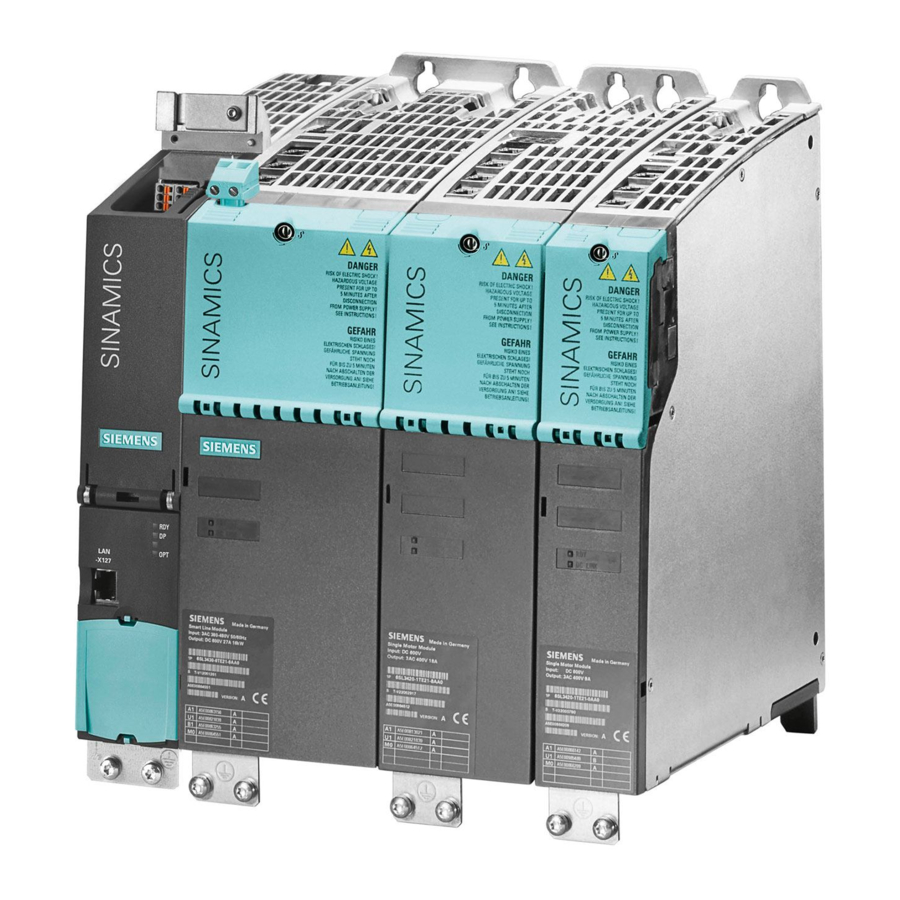
Page 71: Line Modules
Line Modules Introduction The drive line-up is connected to the power supply network via the Line Modules. Line Infeeds generate a DC voltage from the connected line voltage that is used to power the connected Motor Modules. The Line and Interface Modules are suitable for direct operation on TN, IT and TT systems. General characteristics of the Line Modules ●... -
Page 72: Basic Line Modules
Line Modules 3.2 Basic Line Modules Basic Line Modules 3.2.1 Description Basic Line Modules are used for the power infeed into the DC link. They are suitable for applications in which no regenerative energy is produced, or in which the energy exchange takes place between the motor- and the generator-driven axes in the DC link. -
Page 73: Safety Information
Line Modules 3.2 Basic Line Modules Components of the Basic infeed A Basic Infeed comprises a Basic Line Module and an external line connection, which comprises a line filter and a line reactor. Operating principle One or more Motor Modules can be connected to the power supply network via the Basic Line Module. -
Page 74: Interface Description
Line Modules 3.2 Basic Line Modules 3.2.3 Interface description 3.2.3.1 Overview Figure 3-1 Basic Line Module, frame size FB Chassis power units Manual, (GH3), 10/2008, 6SL3097-2AE00-0BP3... - Page 75 Line Modules 3.2 Basic Line Modules Figure 3-2 Basic Line Module, frame size GB Chassis power units Manual, (GH3), 10/2008, 6SL3097-2AE00-0BP3...
-
Page 76: Connection Example
Line Modules 3.2 Basic Line Modules 3.2.3.2 Connection example Figure 3-3 Connection example: Basic Line Module Chassis power units Manual, (GH3), 10/2008, 6SL3097-2AE00-0BP3... -
Page 77: Line/Load Connection
Line Modules 3.2 Basic Line Modules 3.2.3.3 Line/load connection Table 3- 2 Line/load connection of the Basic Line Module Terminals Technical specifications U1, V1, W1 Voltage: 3 AC power input 3-ph. 380 V AC -10 % (-15 % < 1 min) to 3-ph. 480 V AC +10 % •... -
Page 78: X41 Ep Terminals
Line Modules 3.2 Basic Line Modules 3.2.3.5 X41 EP terminals Table 3- 4 X41 terminal strip Terminal Function Technical specifications Not assigned Not assigned EP +24 V (enable pulses) Supply voltage: 24 V DC (20.4 V – 28.8 V) Power consumption: 10 mA EP M1 (enable pulses) Signal propagation times: L →... -
Page 79: Meaning Of The Leds On The Control Interface Board In The Basic Line Module
Line Modules 3.2 Basic Line Modules 3.2.3.8 Meaning of the LEDs on the Control Interface Board in the Basic Line Module Table 3- 6 Meaning of the LEDs on the Control Interface Board in the Basic Line Module LED state Description H200 H201... -
Page 80: Dimension Drawing
Line Modules 3.2 Basic Line Modules 3.2.4 Dimension drawing Dimension drawing, frame size FB The mandatory cooling clearances are indicated by the dotted line. Figure 3-4 Dimension drawing, Basic Line Module, frame sizes FB, side view, front view Chassis power units Manual, (GH3), 10/2008, 6SL3097-2AE00-0BP3... - Page 81 Line Modules 3.2 Basic Line Modules Dimension drawing, frame size GB The mandatory cooling clearances are indicated by the dotted line. Figure 3-5 Dimension drawing, Basic Line Module, frame size GB Side view, rear view Chassis power units Manual, (GH3), 10/2008, 6SL3097-2AE00-0BP3...
-
Page 82: Electrical Connection
Line Modules 3.2 Basic Line Modules 3.2.5 Electrical connection Operating a Basic Line Module from an insulated network (IT system) When the device is operated on an isolated-neutral network (IT system), the connection bracket to the noise suppression capacitor must be removed (e.g.: see "1" in figure below). The interface overview in the section "Interface description"... - Page 83 Line Modules 3.2 Basic Line Modules Adjusting the fan voltage (-T10) The power supply for the device fans (1-ph. 230 V AC) in the Basic Line Module (-T10) is taken from the line supply using transformers. The locations of the transformers are indicated in the interface descriptions.
- Page 84 Line Modules 3.2 Basic Line Modules Table 3- 8 Line voltage assignment for setting the fan transformer (500 V – 690 V 3 AC) Line voltage Tap at the fan transformer (-T10) 500 V ± 10 % 500 V 525 V ± 10 % 525 V 575 V ±...
-
Page 85: Technical Specifications
Line Modules 3.2 Basic Line Modules 3.2.6 Technical specifications Table 3- 9 Technical specifications for Basic Line Modules, 380 V – 480 V 3 AC, part 1 Order number 6SL3330– 1TE34–2AA0 1TE35–3AA0 1TE38–2AA0 1TE41–2AA0 Infeed power - Rated power Pn at 400 V 3 AC - Pmax at 400 V 3 AC DC link current - Rated current I... - Page 86 Line Modules 3.2 Basic Line Modules Order number 6SL3330– 1TE34–2AA0 1TE35–3AA0 1TE38–2AA0 1TE41–2AA0 Dimensions - Width - Height 1164 1164 1164 1653 - Depth Frame size Weight UL listed fuse 3NE1333-2 3NE1334-2 3NE1438-2 3NE1435-2 - Number (connected in parallel) - Rated current - Frame size acc.
- Page 87 Line Modules 3.2 Basic Line Modules Table 3- 10 Technical specifications for Basic Line Modules, 380 V – 480 V 3 AC, part 2 Order number 6SL3330– 1TE41–5AA0 Infeed power - Rated power Pn at 400 V 3 AC - Pmax at 400 V 3 AC 1065 DC link current - Rated current I...
- Page 88 Line Modules 3.2 Basic Line Modules Order number 6SL3330– 1TE41–5AA0 Weight UL listed fuse 3NE1437-2 - Number (connected in parallel) - Rated current - Frame size acc. to DIN 43620-1 The types of protection specified here are mandatory for installing a UL-approved system. Chassis power units Manual, (GH3), 10/2008, 6SL3097-2AE00-0BP3...
- Page 89 Line Modules 3.2 Basic Line Modules Table 3- 11 Technical specifications for Basic Line Modules, 500 V – 690 V 3 AC, part 1 Order number 6SL3330– 1TH33–0AA0 1TH34–3AA0 1TH36–8AA0 1TH41–1AA0 Infeed power - Rated power Pn at 690 V 3 AC - Rated power Pn at 500 V 3 AC - Pmax at 690 V 3 AC 532.5...
- Page 90 Line Modules 3.2 Basic Line Modules Order number 6SL3330– 1TH33–0AA0 1TH34–3AA0 1TH36–8AA0 1TH41–1AA0 Weight UL listed fuse 3NE1230-2 3NE1333-2 3NE1436-2 3NE1334-2 - Number (connected in parallel) - Rated current - Frame size acc. to DIN 43620-1 The types of protection specified here are mandatory for installing a UL-approved system. Chassis power units Manual, (GH3), 10/2008, 6SL3097-2AE00-0BP3...
- Page 91 Line Modules 3.2 Basic Line Modules Table 3- 12 Technical specifications for Basic Line Modules, 500 V – 690 V 3 AC, part 2 Order number 6SL3330– 1TH41–4AA0 Infeed power - Rated power Pn at 690 V 3 AC 1100 - Rated power Pn at 500 V 3 AC - Pmax at 690 V 3 AC 1650...
- Page 92 Line Modules 3.2 Basic Line Modules Order number 6SL3330– 1TH41–4AA0 Weight UL listed fuse 3NE1436-2 - Number (connected in parallel) - Rated current - Frame size acc. to DIN 43620-1 The types of protection specified here are mandatory for installing a UL-approved system. Overload capability The Basic Line Modules have an overload reserve.
-
Page 93: Smart Line Modules
Line Modules 3.3 Smart Line Modules Smart Line Modules 3.3.1 Description Smart Line Modules are infeed/regenerative feedback units. Like the Basic Line Module, they supply energy to the connected Motor Modules, but unlike the Basic Line Module, they can feed back regenerative energy. The infeed occurs over a diode jumper, while stable, line-commutated regenerative feedback takes place via IGBTs with 100 % continuous energy regeneration. - Page 94 Line Modules 3.3 Smart Line Modules Components of the Smart Infeed A Smart Infeed comprises a Smart Line Module and an external line connection, which comprises bridging contactor, precharging input circuit, fuse, and line reactor. Figure 3-9 Overview of Smart Infeed Operating principle One or more Motor Modules can be connected to the power supply network via the Smart Line Module.
-
Page 95: Safety Information
Line Modules 3.3 Smart Line Modules 3.3.2 Safety information WARNING A hazardous voltage will be present in the component for a further 5 minutes after all voltage supplies have been disconnected. Work cannot be carried out until this time has elapsed. -
Page 96: Interface Description
Line Modules 3.3 Smart Line Modules 3.3.3 Interface description 3.3.3.1 Overview Figure 3-10 Smart Line Module, frame size GX Chassis power units Manual, (GH3), 10/2008, 6SL3097-2AE00-0BP3... - Page 97 Line Modules 3.3 Smart Line Modules Figure 3-11 Smart Line Module, frame size HX Chassis power units Manual, (GH3), 10/2008, 6SL3097-2AE00-0BP3...
- Page 98 Line Modules 3.3 Smart Line Modules Figure 3-12 Smart Line Module, frame size JX Chassis power units Manual, (GH3), 10/2008, 6SL3097-2AE00-0BP3...
-
Page 99: Connection Example
Line Modules 3.3 Smart Line Modules 3.3.3.2 Connection example Figure 3-13 Smart Line Module wiring diagram Chassis power units Manual, (GH3), 10/2008, 6SL3097-2AE00-0BP3... -
Page 100: Line/Load Connection
Line Modules 3.3 Smart Line Modules 3.3.3.3 Line/load connection Table 3- 14 Line/load connection of the Smart Line Module Terminals Technical specifications U1, V1, W1 Voltage: 3 AC power input 3-ph. 380 V AC -10 % (-15 % < 1 min) to 3-ph. 480 V AC +10 % •... -
Page 101: X9 Terminal Strip
Line Modules 3.3 Smart Line Modules 3.3.3.4 X9 terminal strip Table 3- 15 X9 terminal strip Terminal Signal name Technical specifications P24V Voltage: 24 V DC (20.4 V – 28.8 V) Power consumption: max. 1.7 A Bridging contactor control Voltage: 230 V AC Power consumption: max. -
Page 102: Drive-Cliq Interfaces X400, X401, X402
Line Modules 3.3 Smart Line Modules 3.3.3.7 DRIVE-CLiQ interfaces X400, X401, X402 Table 3- 17 DRIVE-CLiQ interfaces X400, X401, X402 Signal name Technical specifications Transmit data + Transmit data - Receive data + Reserved, do not use Reserved, do not use Receive data - Reserved, do not use Reserved, do not use... -
Page 103: Meaning Of The Leds On The Control Interface Board In The Smart Line Module
Line Modules 3.3 Smart Line Modules 3.3.3.8 Meaning of the LEDs on the Control Interface Board in the Smart Line Module Table 3- 18 Meaning of the LEDs on the Control Interface Board in the Smart Line Module LED state Description H200 H201... -
Page 104: Dimension Drawing
Line Modules 3.3 Smart Line Modules 3.3.4 Dimension drawing Dimension drawing, frame size GX The mandatory cooling clearances are indicated by the dotted line. Figure 3-14 Dimension drawing Smart Line Module, frame size GX Front view, side view Chassis power units Manual, (GH3), 10/2008, 6SL3097-2AE00-0BP3... - Page 105 Line Modules 3.3 Smart Line Modules Dimension drawing, frame size HX The mandatory cooling clearances are indicated by the dotted line. Figure 3-15 Dimension drawing Smart Line Module, frame size HX Side view, rear view Chassis power units Manual, (GH3), 10/2008, 6SL3097-2AE00-0BP3...
- Page 106 Line Modules 3.3 Smart Line Modules Dimension drawing, frame size JX The mandatory cooling clearances are indicated by the dotted line. Figure 3-16 Dimension drawing Smart Line Module, frame size JX Side view, rear view Chassis power units Manual, (GH3), 10/2008, 6SL3097-2AE00-0BP3...
-
Page 107: Electrical Connection
Line Modules 3.3 Smart Line Modules 3.3.5 Electrical connection Operating a Smart Line Module from an insulated network (IT system) When the device is operated on an isolated-neutral network (IT system), the connection bracket to the noise suppression capacitor must be removed (e.g.: see "1" in figure below). The interface overview in the section "Interface description"... - Page 108 Line Modules 3.3 Smart Line Modules Adjusting the fan voltage (-T10) The power supply for the device fans (1-ph. 230 V AC) in the Smart Line Module (-T10) is taken from the line supply using transformers. The locations of the transformers are indicated in the interface descriptions.
- Page 109 Line Modules 3.3 Smart Line Modules Table 3- 19 Line voltage assignment for setting the fan transformer (380 V – 480 V 3 AC) Line voltage Tap at the fan transformer (-T10) 380 V ± 10 % 380 V 400 V ± 10 % 400 V 440 V ±...
-
Page 110: Technical Specifications
Line Modules 3.3 Smart Line Modules 3.3.6 Technical specifications Table 3- 21 Technical specifications for Smart Line Modules, 380 V – 480 V 3 AC, part 1 Order number 6SL3330– 6TE35-5AA0 6TE37–3AA0 6TE41-1AA0 6TE41–3AA0 Infeed power - Rated power Pn at 400 V 3 AC - Pmax at 400 V 3 AC 532.5 DC link current... - Page 111 Line Modules 3.3 Smart Line Modules Order number 6SL3330– 6TE35-5AA0 6TE37–3AA0 6TE41-1AA0 6TE41–3AA0 Dimensions - Width - Height 1400 1400 1400 1400 - Depth Frame size Weight, approx. UL listed fuse 3NE1435-2 3NE1437-2 3NE1334-2 3NE1436-2 - Number (connected in parallel) - Rated current - Frame size acc.
- Page 112 Line Modules 3.3 Smart Line Modules Table 3- 22 Technical specifications for Smart Line Modules, 380 V – 480 V 3 AC, part 2 Order number 6SL3330– 6TE41–7AA0 Infeed power - Rated power Pn at 400 V 3 AC - Pmax at 400 V 3 AC 1200 DC link current - Rated current I...
- Page 113 Line Modules 3.3 Smart Line Modules Order number 6SL3330– 6TE41–7AA0 Frame size Weight, approx. UL listed fuse 3NE1448-2 - Number (connected in parallel) - Rated current - Frame size acc. to DIN 43620-1 The types of protection specified here are mandatory for installing a UL-approved system. Chassis power units Manual, (GH3), 10/2008, 6SL3097-2AE00-0BP3...
- Page 114 Line Modules 3.3 Smart Line Modules Table 3- 23 Technical specifications for Smart Line Modules, 500 V – 690 V 3 AC Order number 6SL3330– 6TG35–5AA0 6TG38–8AA0 6TG41–2AA0 6TG41–7AA0 Infeed power - Rated power Pn at 690 V 3 AC 1000 1400 - Pmax at 690 V 3 AC...
- Page 115 Line Modules 3.3 Smart Line Modules Order number 6SL3330– 6TG35–5AA0 6TG38–8AA0 6TG41–2AA0 6TG41–7AA0 Frame size Weight, approx. UL listed fuse 3NE1435-2 3NE1448-2 3NE1435-2 3NE1448-2 - Number (connected in parallel) - Rated current - Frame size acc. to DIN 43620-1 The types of protection specified here are mandatory for installing a UL-approved system. Overload capability The Smart Line Modules have an overload reserve.
-
Page 116: Active Line Modules
Line Modules 3.4 Active Line Modules Active Line Modules 3.4.1 Description The self-commutating infeed / regenerative feedback units act as step-up converters and generate a stabilized DC link voltage that is 1.5x greater than the rated line supply voltage. In this way, the connected Motor Modules are isolated from the supply voltage. This improves the dynamic response and control quality because line tolerances and fluctuations do not affect the motor voltage. - Page 117 Line Modules 3.4 Active Line Modules Figure 3-20 Overview of Active Infeed (frame sizes FI/FX and GI/GX) In the case of an Active Infeed with an Active Line Module of frame sizes HX or JX, the bypass contactor is not included in the associated Active Interface Module, but must be provided separately.
-
Page 118: Safety Information
Line Modules 3.4 Active Line Modules 3.4.2 Safety information WARNING A hazardous voltage will be present in the component for a further 5 minutes after all voltage supplies have been disconnected. Work cannot be carried out until this time has elapsed. -
Page 119: Interface Description
Line Modules 3.4 Active Line Modules 3.4.3 Interface description 3.4.3.1 Overview Figure 3-22 Active Line Module, frame size FX Chassis power units Manual, (GH3), 10/2008, 6SL3097-2AE00-0BP3... - Page 120 Line Modules 3.4 Active Line Modules Figure 3-23 Active Line Module, frame size GX Chassis power units Manual, (GH3), 10/2008, 6SL3097-2AE00-0BP3...
- Page 121 Line Modules 3.4 Active Line Modules Figure 3-24 Active Line Module, frame size HX Chassis power units Manual, (GH3), 10/2008, 6SL3097-2AE00-0BP3...
- Page 122 Line Modules 3.4 Active Line Modules Figure 3-25 Active Line Module, frame size JX Chassis power units Manual, (GH3), 10/2008, 6SL3097-2AE00-0BP3...
-
Page 123: Connection Example
Line Modules 3.4 Active Line Modules 3.4.3.2 Connection example Figure 3-26 Active Line Module wiring diagram Chassis power units Manual, (GH3), 10/2008, 6SL3097-2AE00-0BP3... -
Page 124: Line/Load Connection
Line Modules 3.4 Active Line Modules 3.4.3.3 Line/load connection Table 3- 25 Line/load connection of the Active Line Module Terminals Technical specifications U1, V1, W1 Voltage: 3 AC power input 3-ph. 380 V AC -10 % (-15 % < 1 min) to 3-ph. 480 V AC +10 % •... -
Page 125: X41 Ep Terminals
Line Modules 3.4 Active Line Modules 3.4.3.5 X41 EP terminals Table 3- 27 X41 terminal strip Terminal Function Technical specifications Not assigned Not assigned EP +24 V (enable pulses) Supply voltage: 24 V DC (20.4 V – 28.8 V) Power consumption: 10 mA EP M1 (enable pulses) Signal propagation times: L →... -
Page 126: Meaning Of The Leds On The Control Interface Board In The Active Line Module
Line Modules 3.4 Active Line Modules 3.4.3.8 Meaning of the LEDs on the Control Interface Board in the Active Line Module Table 3- 29 Meaning of the LEDs on the Control Interface Board in the Active Line Module LED state Description H200 H201... -
Page 127: Dimension Drawing
Line Modules 3.4 Active Line Modules 3.4.4 Dimension drawing Dimension drawing, frame size FX The mandatory cooling clearances are indicated by the dotted line. Figure 3-27 Dimension drawing Active Line Module, frame size FX Front view, side view Chassis power units Manual, (GH3), 10/2008, 6SL3097-2AE00-0BP3... - Page 128 Line Modules 3.4 Active Line Modules Dimension drawing, frame size GX The mandatory cooling clearances are indicated by the dotted line. Figure 3-28 Dimension drawing Active Line Module, frame size GX Front view, side view Chassis power units Manual, (GH3), 10/2008, 6SL3097-2AE00-0BP3...
- Page 129 Line Modules 3.4 Active Line Modules Dimension drawing, frame size HX The mandatory cooling clearances are indicated by the dotted line. Figure 3-29 Dimension drawing Active Line Module, frame size HX Side view, rear view Chassis power units Manual, (GH3), 10/2008, 6SL3097-2AE00-0BP3...
- Page 130 Line Modules 3.4 Active Line Modules Dimension drawing, frame size JX The mandatory cooling clearances are indicated by the dotted line. Figure 3-30 Dimension drawing Active Line Module, frame size JX Side view, rear view Chassis power units Manual, (GH3), 10/2008, 6SL3097-2AE00-0BP3...
-
Page 131: Electrical Connection
Line Modules 3.4 Active Line Modules 3.4.5 Electrical connection Adjusting the fan voltage (-T10) The power supply for the device fans (1-ph. 230 V AC) in the Active Line Module (-T10) is taken from the line supply using transformers. The locations of the transformers are indicated in the interface descriptions. - Page 132 Line Modules 3.4 Active Line Modules Table 3- 30 Line voltage assignments for setting the fan transformer (380 to 480 V AC, 3-phase) Line voltage Tap at the fan transformer (-T10) 380 V ± 10 % 380 V 400 V ± 10 % 400 V 440 V ±...
-
Page 133: Technical Specifications
Line Modules 3.4 Active Line Modules 3.4.6 Technical specifications Table 3- 32 Technical specifications for Active Line Modules, 380 V – 480 V 3 AC, part 1 Order number 6SL3330– 7TE32–1AA0 7TE32–6AA0 7TE33–8AA0 7TE35–0AA0 Infeed/regenerative feedback power - Rated power Pn at 400 V 3 AC - Pmax at 400 V 3 AC 352.5 DC link current... - Page 134 Line Modules 3.4 Active Line Modules Order number 6SL3330– 7TE32–1AA0 7TE32–6AA0 7TE33–8AA0 7TE35–0AA0 Frame size Weight UL listed fuse 3NE1230-2 3NE1331-2 3NE1334-2 3NE1436-2 - Number (connected in parallel) - Rated current - Frame size acc. to DIN 43620-1 The types of protection specified here are mandatory for installing a UL-approved system. Chassis power units Manual, (GH3), 10/2008, 6SL3097-2AE00-0BP3...
- Page 135 Line Modules 3.4 Active Line Modules Table 3- 33 Technical specifications for Active Line Modules, 380 V – 480 V 3 AC, part 2 Order number 6SL3330– 7TE36–1AA0 7TE38–4AA0 7TE41–0AA0 7TE41–4AA0 Infeed/regenerative feedback power - Rated power Pn at 400 V 3 AC - Pmax at 400 V 3 AC 1350 DC link current...
- Page 136 Line Modules 3.4 Active Line Modules Order number 6SL3330– 7TE36–1AA0 7TE38–4AA0 7TE41–0AA0 7TE41–4AA0 Weight UL listed fuse 3NE1438-2 3NE1334-2 3NE1436-2 3NE1448-2 - Number (connected in parallel) - Rated current - Frame size acc. to DIN 43620-1 The types of protection specified here are mandatory for installing a UL-approved system. Chassis power units Manual, (GH3), 10/2008, 6SL3097-2AE00-0BP3...
- Page 137 Line Modules 3.4 Active Line Modules Table 3- 34 Technical specifications for Active Line Modules, 500V–690 V 3 AC Order number 6SL3330– 7TG35–8AA0 7TG37–4AA0 7TG41–0AA0 7TG41–3AA0 Infeed/regenerative feedback power - Rated power Pn at 690 V 3 AC 1100 1400 - Rated power Pn at 500 V 3 AC 1000 - Pmax at 690 V 3 AC...
- Page 138 Line Modules 3.4 Active Line Modules Order number 6SL3330– 7TG35–8AA0 7TG37–4AA0 7TG41–0AA0 7TG41–3AA0 Weight UL listed fuse 3NE1447-2 3NE1448-2 3NE1436-2 3NE1438-2 - Number (connected in parallel) - Rated current - Frame size acc. to DIN 43620-1 The types of protection specified here are mandatory for installing a UL-approved system. Overload capability The Active Line Modules have an overload reserve.
-
Page 139: Motor Modules
Motor Modules Description A Motor Module is a power unit (DC-AC inverter) that provides the power supply for the motor connected to it. Power is supplied by means of the DC link of the drive unit. A Motor Module must be connected to a Control Unit via DRIVE-CLiQ. The open-loop and closed-loop control functions are stored in the Control Unit. - Page 140 Motor Modules 4.1 Description Operating principle Motor Modules are designed for multi-axis drive systems and are controlled by either a CU320 or a SIMOTION D Control Unit. Motor Modules are interconnected by means of a shared DC busbar. One or more Motor Modules are supplied with energy for the motors via the DC link. Both synchronous and induction motors can be operated.
-
Page 141: Safety Information
Motor Modules 4.2 Safety information Safety information WARNING After disconnecting all the supply voltages, a hazardous voltage will be present in all components for another 5 minutes. Work cannot be carried out until this time has elapsed. Before starting work, you should also measure the voltage after the 5 minutes have elapsed. -
Page 142: Interface Description
Motor Modules 4.3 Interface description Interface description 4.3.1 Overview Figure 4-1 Motor Module, frame size FX, with order numbers 6SL3320–1Txxx–xAA3 Chassis power units Manual, (GH3), 10/2008, 6SL3097-2AE00-0BP3... - Page 143 Motor Modules 4.3 Interface description Figure 4-2 Motor Module, frame size FX, with order numbers 6SL3320–1Txxx–xAA0 Chassis power units Manual, (GH3), 10/2008, 6SL3097-2AE00-0BP3...
- Page 144 Motor Modules 4.3 Interface description Figure 4-3 Motor Module, frame size GX, with order numbers 6SL3320–1Txxx–xAA3 Chassis power units Manual, (GH3), 10/2008, 6SL3097-2AE00-0BP3...
- Page 145 Motor Modules 4.3 Interface description Figure 4-4 Motor Module, frame size GX, with order numbers 6SL3320–1Txxx–xAA0 Chassis power units Manual, (GH3), 10/2008, 6SL3097-2AE00-0BP3...
- Page 146 Motor Modules 4.3 Interface description Figure 4-5 Motor Module, frame size HX, with order numbers 6SL3320–1Txxx–xAA3 Chassis power units Manual, (GH3), 10/2008, 6SL3097-2AE00-0BP3...
- Page 147 Motor Modules 4.3 Interface description Figure 4-6 Motor Module, frame size HX, with order numbers 6SL3320–1Txxx–xAA0 Chassis power units Manual, (GH3), 10/2008, 6SL3097-2AE00-0BP3...
- Page 148 Motor Modules 4.3 Interface description Figure 4-7 Motor Module, frame size JX, with order numbers 6SL3320–1Txxx–xAA3 Chassis power units Manual, (GH3), 10/2008, 6SL3097-2AE00-0BP3...
- Page 149 Motor Modules 4.3 Interface description Figure 4-8 Motor Module, frame size JX, with order numbers 6SL3320–1Txxx–xAA0 Chassis power units Manual, (GH3), 10/2008, 6SL3097-2AE00-0BP3...
-
Page 150: Connection Example
Motor Modules 4.3 Interface description 4.3.2 Connection example Figure 4-9 Connection example of Motor Modules, with order numbers 6SL3320–1Txxx–xAA3 Chassis power units Manual, (GH3), 10/2008, 6SL3097-2AE00-0BP3... - Page 151 Motor Modules 4.3 Interface description Figure 4-10 Connection example of Motor Modules, with order numbers 6SL3320–1Txxx–xAA0 Chassis power units Manual, (GH3), 10/2008, 6SL3097-2AE00-0BP3...
-
Page 152: Dc Link/Motor Connection
Motor Modules 4.3 Interface description 4.3.3 DC link/motor connection Table 4- 2 DC link/motor connection of the Motor Module Terminals Technical specifications DCP, DCN Voltage: DC power input 510 V to 720 V DC • 675 V to 1035 V DC •... -
Page 153: X9 Terminal Strip
Motor Modules 4.3 Interface description 4.3.4 X9 terminal strip Table 4- 3 X9 terminal strip Terminal Signal name Technical specifications P24V Voltage: 24 V DC (20.4 V – 28.8 V) Power consumption: max. 1.4 A Reserved, do not use Reserved, do not use Reserved, do not use Reserved, do not use Connection for fan supply... - Page 154 Motor Modules 4.3 Interface description CAUTION The temperature sensor must be connected in shielded form. The shielding must be attached to the shield support of the motor module. NOTICE The KTY temperature sensor must be connected with the correct polarity. NOTICE The function of the EP terminals is only available when Safety Integrated Basic Functions are enabled.
-
Page 155: X42 Terminal Strip
Motor Modules 4.3 Interface description 4.3.7 X42 terminal strip Table 4- 7 Terminal strip X42 brake control and monitoring, with order numbers 6SL3320–1Txxx–xAA3 Terminal Function Technical specifications P24L Voltage supply for Control Unit, Sensor Module and Terminal Module (18 to 28.8 V) Max. -
Page 156: Drive-Cliq Interfaces X400, X401, X402
Motor Modules 4.3 Interface description 4.3.9 DRIVE-CLiQ interfaces X400, X401, X402 Table 4- 9 DRIVE-CLiQ interfaces X400, X401, X402 Signal name Technical specifications Transmit data + Transmit data - Receive data + Reserved, do not use Reserved, do not use Receive data - Reserved, do not use Reserved, do not use... -
Page 157: Meaning Of The Leds On The Control Interface Module In The Motor Module
Flashing light There is a fault. If the LED continues to flash after you have performed a POWER ON, please contact your Siemens service center. WARNING Irrespective of the state of the LED "DC LINK", hazardous DC link voltages can always be present. -
Page 158: Meaning Of The Leds On The Control Interface Board In The Motor Module
Motor Modules 4.3 Interface description 4.3.11 Meaning of the LEDs on the Control Interface Board in the Motor Module Note The description applies to Motor Modules with the order number 6SL3320–1Txxx–xAA0. Table 4- 12 Meaning of the LEDs on the Control Interface Board in the Motor Module LED state Description H200... -
Page 159: Dimension Drawing
Motor Modules 4.4 Dimension drawing Dimension drawing Dimension drawing, frame size FX The mandatory cooling clearances are indicated by the dotted line. Figure 4-11 Dimension drawing Motor Module, frame size FX Front view, side view Chassis power units Manual, (GH3), 10/2008, 6SL3097-2AE00-0BP3... - Page 160 Motor Modules 4.4 Dimension drawing Dimension drawing, frame size GX The mandatory cooling clearances are indicated by the dotted line. Figure 4-12 Dimension drawing Motor Module, frame size GX Front view, side view Chassis power units Manual, (GH3), 10/2008, 6SL3097-2AE00-0BP3...
- Page 161 Motor Modules 4.4 Dimension drawing Dimension drawing, frame size HX The mandatory cooling clearances are indicated by the dotted line. Figure 4-13 Dimension drawing Motor Module, frame size HX Side view, rear view Chassis power units Manual, (GH3), 10/2008, 6SL3097-2AE00-0BP3...
- Page 162 Motor Modules 4.4 Dimension drawing Dimension drawing, frame size JX The mandatory cooling clearances are indicated by the dotted line. Figure 4-14 Dimension drawing Motor Module, frame size JX Side view, rear view Chassis power units Manual, (GH3), 10/2008, 6SL3097-2AE00-0BP3...
-
Page 163: Electrical Connection
Motor Modules 4.5 Electrical connection Electrical connection Adjusting the fan voltage (-T10) The power supply for the device fans (1-ph. 230 V AC) in the Motor Module (-T10) is taken from the line supply using transformers. The locations of the transformers are indicated in the interface descriptions. - Page 164 Motor Modules 4.5 Electrical connection Table 4- 13 Line voltage assignments for setting the fan transformer (380 to 480 V AC, 3-phase) Line voltage Tap at the fan transformer (-T10) 380 V ± 10 % 380 V 400 V ± 10 % 400 V 440 V ±...
-
Page 165: Technical Specifications
Motor Modules 4.6 Technical specifications Technical specifications 4.6.1 510 V DC – 720 V DC Motor Modules Table 4- 15 Technical specifications for Motor Module, 510 V DC – 720 V DC, Part 1 Order number 6SL3320– 1TE32–1AA0 1TE32–6AA0 1TE33–1AA0 1TE33–8AA0 1TE32–1AA3 1TE32–6AA3... - Page 166 Motor Modules 4.6 Technical specifications Order number 6SL3320– 1TE32–1AA0 1TE32–6AA0 1TE33–1AA0 1TE33–8AA0 1TE32–1AA3 1TE32–6AA3 1TE33–1AA3 1TE33–8AA3 Dimensions - Width - Height 1400 1400 1533 1533 - Depth Frame size Weight Rated power of a typical standard induction motor at 400 V 3 AC. Chassis power units Manual, (GH3), 10/2008, 6SL3097-2AE00-0BP3...
- Page 167 Motor Modules 4.6 Technical specifications Table 4- 16 Technical specifications for Motor Module, 510 V DC – 720 V DC, Part 2 Order number 6SL3320– 1TE35–0AA0 1TE36–1AA0 1TE37–5AA0 1TE38–4AA0 1TE35–0AA3 1TE36–1AA3 1TE37–5AA3 1TE38–4AA3 Output current - Rated current I - Base load current I - Base load current I - for S6 operation (40 %) I - Max.
- Page 168 Motor Modules 4.6 Technical specifications Order number 6SL3320– 1TE35–0AA0 1TE36–1AA0 1TE37–5AA0 1TE38–4AA0 1TE35–0AA3 1TE36–1AA3 1TE37–5AA3 1TE38–4AA3 Frame size Weight Rated power of a typical standard induction motor at 400 V 3 AC. Chassis power units Manual, (GH3), 10/2008, 6SL3097-2AE00-0BP3...
- Page 169 Motor Modules 4.6 Technical specifications Table 4- 17 Technical specifications for Motor Module, 510 V DC – 720 V DC, Part 3 Order number 6SL3320– 1TE41–0AA0 1TE41–2AA0 1TE41–4AA0 1TE41–0AA3 1TE41–2AA3 1TE41–4AA3 Output current - Rated current I 1260 1405 - Base load current I 1230 1370 - Base load current I...
- Page 170 Motor Modules 4.6 Technical specifications Order number 6SL3320– 1TE41–0AA0 1TE41–2AA0 1TE41–4AA0 1TE41–0AA3 1TE41–2AA3 1TE41–4AA3 Frame size Weight Rated power of a typical standard induction motor at 400 V 3 AC. Chassis power units Manual, (GH3), 10/2008, 6SL3097-2AE00-0BP3...
-
Page 171: Dc - 1035 V Dc Motor Modules
Motor Modules 4.6 Technical specifications 4.6.2 675 V DC – 1035 V DC Motor Modules Table 4- 18 Technical specifications for Motor Module, 675 V DC – 1035 V DC, Part 1 Order number 6SL3320– 1TG28–5AA0 1TG31–0AA0 1TG31–2AA0 1TG31–5AA0 1TG28–5AA3 1TG31–0AA3 1TG31–2AA3 1TG31–5AA3... - Page 172 Motor Modules 4.6 Technical specifications Order number 6SL3320– 1TG28–5AA0 1TG31–0AA0 1TG31–2AA0 1TG31–5AA0 1TG28–5AA3 1TG31–0AA3 1TG31–2AA3 1TG31–5AA3 Frame size Weight Rated power of a typical standard induction motor at 690 V 3 AC. Chassis power units Manual, (GH3), 10/2008, 6SL3097-2AE00-0BP3...
- Page 173 Motor Modules 4.6 Technical specifications Table 4- 19 Technical specifications for Motor Module, 675 V DC – 1035 V DC, Part 2 Order number 6SL3320– 1TG31–8AA0 1TG32–2AA0 1TG32–6AA0 1TG33–3AA0 1TG31–8AA3 1TG32–2AA3 1TG32–6AA3 1TG33–3AA3 Output current - Rated current I - Base load current I - Base load current I - Max.
- Page 174 Motor Modules 4.6 Technical specifications Table 4- 20 Technical specifications for Motor Module, 675 V DC – 1035 V DC, Part 3 Order number 6SL3320– 1TG34–1AA0 1TG34–7AA0 1TG35–8AA0 1TG37–4AA0 1TG34–1AA3 1TG34–7AA3 1TG35–8AA3 1TG37–4AA3 Output current - Rated current I - Base load current I - Base load current I - Max.
- Page 175 Motor Modules 4.6 Technical specifications Table 4- 21 Technical specifications for Motor Module, 675 V DC – 1035 V DC, Part 4 Order number 6SL3320– 1TG38–1AA0 1TG38–8AA0 1TG41–0AA0 1TG41–3AA0 1TG38–1AA3 1TG38–8AA3 1TG41–0AA3 1TG41–3AA3 Output current - Rated current I 1025 1270 - Base load current I 1000...
-
Page 176: Overload Capability
Motor Modules 4.6 Technical specifications 4.6.3 Overload capability The Motor Modules have an overload reserve e.g. to handle breakaway torques. In the case of drives with overload requirements, the appropriate base-load current must, therefore, be used as a basis for the required load. The criterion for overload is that the Motor Module is operated with its base load current before and after the overload occurs (a load duration of 300 s is used as a basis here). -
Page 177: Current De-Rating Depending On The Pulse Frequency
Motor Modules 4.6 Technical specifications High overload The base load current for a high overload I is based on a duty cycle of 150 % for 60 s or 160 % for 10 s. Figure 4-17 High overload 4.6.4 Current de-rating depending on the pulse frequency When the pulse frequency is increased, the derating factor of the output current must be taken into account. - Page 178 Motor Modules 4.6 Technical specifications Table 4- 23 Derating factor of the output current as a function of the pulse frequency for devices with a rated pulse frequency of 1.25 kHz Order no. Power [kW] Output current for a Derating factor for a 6SL3320-...
-
Page 179: Parallel Connection Of Motor Modules
Motor Modules 4.6 Technical specifications 4.6.5 Parallel connection of Motor Modules The following rules must be observed when connecting Motor Modules in parallel: ● Up to 4 identical Motor Modules can be connected in parallel. ● A common Control Unit is required whenever the modules are connected in parallel. ●... - Page 180 Motor Modules 4.6 Technical specifications Table 4- 26 675 V DC – 1035 V DC Motor Modules Order number Power [kW] Output current [A] Minimum cable length [m] 6SL3320-1TG28-5AAx 6SL3320-1TG31-0AAx 6SL3320-1TG31-2AAx 6SL3320-1TG31-5AAx 6SL3320-1TG31-8AAx 6SL3320-1TG32-2AAx 6SL3320-1TG32-6AAx 6SL3320-1TG33-3AAx 6SL3320-1TG34-1AAx 6SL3320-1TG34-7AAx 6SL3320-1TG35-8AAx 6SL3320-1TG37-4AAx 6SL3320-1TG38-1AAx 6SL3320-1TG38-8AAx 6SL3320-1TG41-0AAx...
-
Page 181: Dc Link Components
DC link components Braking Module 5.1.1 Description A Braking Module and an external braking resistor are required to bring drives to a controlled standstill in the event of a power failure (e.g. emergency retraction or EMERGENCY STOP category 1) or limit the DC link voltage if the generator is operated for a short period of time, for example because there is no regenerative feedback capability into the supply network when a Basic Line Module is used). -
Page 182: Safety Information
CAUTION The connection to the braking resistors must be short-circuit/ground-fault proof. Note If braking resistors are used that have not been released by SIEMENS for SINAMICS, then the braking resistors could be destroyed. Chassis power units Manual, (GH3), 10/2008, 6SL3097-2AE00-0BP3... -
Page 183: Interface Description
DC link components 5.1 Braking Module 5.1.3 Interface description 5.1.3.1 Braking Module for frame sizes FX, FB Figure 5-2 Braking Module for Active Line Module / Motor Module, frame size FX and for Basic Line Module, frame size FB Note With this Braking Module, the R1 and DCPA interfaces use the same connection. -
Page 184: Braking Module For Frame Sizes Gx, Gb
DC link components 5.1 Braking Module 5.1.3.2 Braking Module for frame sizes GX, GB Figure 5-3 Braking Module for Smart Line Module / Active Line Module / Motor Module, frame size GX and for Basic Line Module, frame size GB Note With this Braking Module, the R1 and DCPA interfaces use the same connection. -
Page 185: Braking Module For Frame Sizes Hx, Jx
DC link components 5.1 Braking Module 5.1.3.3 Braking Module for frame sizes HX, JX Figure 5-4 Braking Module for Smart Line Module / Active Line Module / Motor Module, frame sizes HX / JX Chassis power units Manual, (GH3), 10/2008, 6SL3097-2AE00-0BP3... -
Page 186: Connection Example
DC link components 5.1 Braking Module 5.1.3.4 Connection example Figure 5-5 Connection example for Braking Module 5.1.3.5 Braking resistor connection Table 5- 1 Braking resistor connection Terminal Designation Braking resistor connection R+ Braking resistor connection R- Recommended conductor cross-sections: for 25/125 kW: 35 mm , for 50/250 kW: 50 mm Chassis power units Manual, (GH3), 10/2008, 6SL3097-2AE00-0BP3... -
Page 187: X21 Digital Inputs/Outputs
Applying a high signal to terminal X21.3 inhibits the Braking Module. On a falling edge, pending error signals are acknowledged. Note You will find setting instructions for wiring the signals in the SINAMICS S120 Function Manual. 5.1.3.7 S1 Threshold switch The response threshold at which the Braking Module is activated and the DC link voltage generated during braking are specified in the following table. - Page 188 DC link components 5.1 Braking Module Table 5- 3 Response thresholds of the Braking Modules Voltage Response Switch Remark threshold position 380 V - 480 V 673 V 774 V is the default factory setting. With supply voltages 3 AC of between 380 V and 400 V 3 AC, the response 774 V threshold can be set to 673 V to reduce the voltage stress...
-
Page 189: Installation
DC link components 5.1 Braking Module 5.1.4 Installation 5.1.4.1 Installing the Braking Module in an Active Line Module / Motor Module, frame size FX Figure 5-6 Installing the Braking Module in an Active Line Module / Motor Module, frame size FX – steps 1 - 3 Chassis power units Manual, (GH3), 10/2008, 6SL3097-2AE00-0BP3... - Page 190 DC link components 5.1 Braking Module Figure 5-7 Installing the Braking Module in an Active Line Module / Motor Module, frame size FX – steps 4 - 6 Chassis power units Manual, (GH3), 10/2008, 6SL3097-2AE00-0BP3...
- Page 191 DC link components 5.1 Braking Module Installing the Braking Module The steps for the installation procedure are numbered in accordance with the diagrams in front of them. 1. Unscrew the 2 M6 screws from the front cover and lift off the cover. 2.
-
Page 192: Installing The Braking Module In A Smart Line Module / Active Line Module / Motor Module, Frame Size Gx
DC link components 5.1 Braking Module 5.1.4.2 Installing the Braking Module in a Smart Line Module / Active Line Module / Motor Module, frame size GX Figure 5-8 Installing the Braking Module in a Smart Line Module / Active Line Module / Motor Module, frame size GX –... - Page 193 DC link components 5.1 Braking Module Figure 5-9 Installing the Braking Module in a Smart Line Module / Active Line Module / Motor Module, frame size GX – steps 4 - 6 Chassis power units Manual, (GH3), 10/2008, 6SL3097-2AE00-0BP3...
- Page 194 DC link components 5.1 Braking Module Installing the Braking Module The steps for the installation procedure are numbered in accordance with the diagrams in front of them. 1. Unscrew the 2 M6 screws from the front cover and lift off the cover. 2.
-
Page 195: Installing The Braking Module In A Smart Line Module / Active Line Module / Motor Module, Frame Size Hx
DC link components 5.1 Braking Module 5.1.4.3 Installing the Braking Module in a Smart Line Module / Active Line Module / Motor Module, frame size HX Figure 5-10 Installing the Braking Module in a Smart Line Module / Active Line Module / Motor Module, frame size HX Installing the Braking Module The steps for the installation procedure are numbered in accordance with the diagram in... -
Page 196: Installing The Braking Module In A Smart Line Module / Active Line Module / Motor Module, Frame Size Jx
DC link components 5.1 Braking Module 5.1.4.4 Installing the Braking Module in a Smart Line Module / Active Line Module / Motor Module, frame size JX Figure 5-11 Installing the Braking Module in a Smart Line Module / Active Line Module / Motor Module, frame size JX Installing the Braking Module The steps for the installation procedure are numbered in accordance with the diagram. -
Page 197: Installing The Braking Module In A Basic Line Module, Frame Size Fb
DC link components 5.1 Braking Module 5.1.4.5 Installing the Braking Module in a Basic Line Module, frame size FB Figure 5-12 Installing the Braking Module in a Basic Line Module, frame size FB Chassis power units Manual, (GH3), 10/2008, 6SL3097-2AE00-0BP3... - Page 198 DC link components 5.1 Braking Module Installing the Braking Module The steps for the installation procedure are numbered in accordance with the diagram. 1. Unscrew the 3 screws for the blanking plate. Remove the plate. 2. Insert the Braking Module where the cover used to be and secure it using the 3 screws (from step 1).
-
Page 199: Installing The Braking Module In A Basic Line Module, Frame Size Gb
DC link components 5.1 Braking Module 5.1.4.6 Installing the Braking Module in a Basic Line Module, frame size GB Figure 5-13 Installing the Braking Module in a Basic Line Module, frame size GB Chassis power units Manual, (GH3), 10/2008, 6SL3097-2AE00-0BP3... - Page 200 DC link components 5.1 Braking Module Installing the Braking Module Note To install a frame size GX Braking Module in a frame size GB Basic Line Module a cable harness set is required, which is available under order number 6SL3366-2NG00-0AA0. The steps for the installation procedure are numbered in accordance with the diagram.
-
Page 201: Technical Specifications
DC link components 5.1 Braking Module 5.1.5 Technical specifications Table 5- 4 Technical specifications of Braking Modules, 380 V – 480 V 3 AC Braking Module 6SL3300- 1AE31-3AA0 1AE32-5AA0 1AE32-5BA0 Suitable for installation in: Smart Line Module / Active Line Module / Motor Module, frame size HX / JX Basic Line Module, frame size... - Page 202 DC link components 5.1 Braking Module Table 5- 5 Technical specifications of Braking Modules, 500 V – 600 V 3 AC Braking Module 6SL3300- 1AF31-3AA0 1AF32-5AA0 1AF32-5BA0 Suitable for installation in: Smart Line Module / Active Line Module / Motor Module, frame size HX / JX Basic Line Module, frame size power (rated power)
- Page 203 DC link components 5.1 Braking Module Table 5- 6 Technical specifications of Braking Modules, 660 V – 690 V 3 AC Braking Module 6SL3300- 1AH31-3AA0 1AH32-5AA0 1AH32-5BA0 Suitable for installation in: Smart Line Module / Active Line Module / Motor Module, frame size HX / JX Basic Line Module, frame size power (rated power)
-
Page 204: Braking Resistors
DC link components 5.2 Braking resistors Braking resistors 5.2.1 Description The excess energy of the DC link is dissipated via the braking resistor. The braking resistor is connected to a Braking Module. The braking resistor is positioned outside the cabinet unit or switchgear room. This enables the resulting heat loss around the Basic Line Modules, Smart Line Modules, Active Line Modules, or Motor Modules to be dissipated. -
Page 205: Safety Information
DC link components 5.2 Braking resistors 5.2.2 Safety information CAUTION A cooling clearance of 200 m must be maintained on all sides of the component (with ventilation meshes). CAUTION The braking resistor cables must be laid in such a way that they are short-circuit and ground-fault proof. -
Page 206: Dimension Drawing
DC link components 5.2 Braking resistors 5.2.3 Dimension drawing Figure 5-14 Dimension drawing braking resistor 25 kW/125 kW Figure 5-15 Dimension drawing braking resistor 50 kW/250 kW Chassis power units Manual, (GH3), 10/2008, 6SL3097-2AE00-0BP3... -
Page 207: Electrical Connection
DC link components 5.2 Braking resistors 5.2.4 Electrical connection WARNING The Braking Module must only be connected when the Basic Line Module, Smart Line Module, Active Line Module, or Motor Module has been disconnected from the power supply and the DC link has been discharged. CAUTION The braking resistor cables must be laid in such a way that they are short-circuit and ground-fault proof. -
Page 208: Technical Specifications
DC link components 5.2 Braking resistors 5.2.5 Technical specifications Table 5- 8 Technical specifications of braking resistors 380 V – 480 V 3 AC Order number Unit 6SL3000-1BE31-3AA0 6SL3000-1BE32-5AA0 (rated power) (peak power) Max. current Resistance Ω 4.4 (± 7.5 %) 2.2 (±... - Page 209 DC link components 5.2 Braking resistors Duty cycle Figure 5-16 Duty cycle for braking resistors Chassis power units Manual, (GH3), 10/2008, 6SL3097-2AE00-0BP3...
- Page 210 DC link components 5.2 Braking resistors Chassis power units Manual, (GH3), 10/2008, 6SL3097-2AE00-0BP3...
-
Page 211: Motor-Side Power Components
Motor-side power components Sine-wave filter 6.1.1 Description If a sine-wave filter is connected to the output of the Motor Module, the voltage between the motor terminals is virtually sinusoidal. This reduces the voltage load on the motor windings and prevents motor noise that would be induced by the pulse frequency. Sine-wave filters are available up to a converter type power rating of 250 kW (without consideration for derating). -
Page 212: Safety Information
• Outgoing cable to the load 1U2, 1V2, 1W2. Non-observance may damage the sine-wave filter. CAUTION If sine-wave filters are used that have not been approved for SINAMICS by SIEMENS, the Motor Modules may be damaged or may malfunction. CAUTION The surface temperature of the sine-wave filters can exceed 80 °C. -
Page 213: Dimension Drawing
Motor-side power components 6.1 Sine-wave filter 6.1.3 Dimension drawing Mounting hole Figure 6-2 Dimension drawing, sine-wave filter Chassis power units Manual, (GH3), 10/2008, 6SL3097-2AE00-0BP3... -
Page 214: Technical Specifications
Motor-side power components 6.1 Sine-wave filter Table 6- 1 Dimensions of the sine-wave filter (all values in mm) 6SL3000- 2CE32-3AA0 2CE32-8AA0 2CE33-3AA0 2CE34-1AA0 The lengths n1, n2 and n3 correspond to the drill hole spacing 6.1.4 Technical specifications Table 6- 2 Technical specifications of sine-wave filters 380 V –... -
Page 215: Motor Reactors
Note The connecting cables to the Motor Module must be kept as short as possible (max. 5 m). CAUTION Using motor reactors not approved by SIEMENS for SINAMICS can result in thermal damage to the reactor. CAUTION The surface temperature of the motor reactors can exceed 80 °C. -
Page 216: Dimension Drawing
Motor-side power components 6.2 Motor reactors 6.2.3 Dimension drawing Figure 6-3 Dimension drawing, motor reactor Chassis power units Manual, (GH3), 10/2008, 6SL3097-2AE00-0BP3... - Page 217 Motor-side power components 6.2 Motor reactors Table 6- 3 Dimensions of motor reactor, 380 V – 480 V 3 AC, part 1 (all specifications in mm) 6SL3000- 2BE32-1AA0 2BE32-6AA0 2BE33-2AA0 2BE33-8AA0 2BE35-0AA0 Connection type Type 1 Type 1 Type 1 Type 1 Type 2 12.5...
- Page 218 Motor-side power components 6.2 Motor reactors Table 6- 5 Dimensions of motor reactor, 500 V – 690 V 3 AC, part 1 (all specifications in mm) 6SL3000- 2AH31-0AA0 2AH31-5AA0 2AH31-8AA0 2AH32-4AA0 2AH32-6AA0 Connection type Type 1 Type 1 Type 1 Type 1 Type 1 12.5...
- Page 219 Motor-side power components 6.2 Motor reactors Table 6- 7 Dimensions of motor reactor, 500 V – 690 V 3 AC, part 3 (all specifications in mm) 6SL3000- 2AH41-0AA0 2AH41-1AA0 2AH41-3AA0 Connection type Type 1 Type 1 Type 1 79.5 94.5 94.5 Lengths n1 and n2 correspond to the distance between holes Chassis power units...
-
Page 220: Technical Specifications
Motor-side power components 6.2 Motor reactors 6.2.4 Technical specifications Table 6- 8 Technical specifications of motor reactors, 380 V – 480 V 3 AC, part 1 Order number 6SL3000- 2BE32-1AA0 2BE32-6AA0 2BE33-2AA0 2BE33-8AA0 Suitable for Motor Module 6SL3320- 1TE32-1AA0 1TE32-6AA0 1TE33-1AA0 1TE33-8AA0 Unit rating of the Motor Module... - Page 221 Motor-side power components 6.2 Motor reactors Table 6- 10 Technical specifications of motor reactors, 380 V – 480 V 3 AC, part 3 Order number 6SL3000- 2AE41-0AA0 2AE41-4AA0 2AE41-4AA0 Suitable for Motor Module 6SL3320- 1TE41-0AA0 1TE41-2AA0 1TE41-4AA0 Unit rating of the Motor Module Rated current 1405 1405...
- Page 222 Motor-side power components 6.2 Motor reactors Table 6- 12 Technical specifications of motor reactors, 500 V – 690 V 3 AC, part 2 Order number 6SL3000- 2AH31-8AA0 2AH32-4AA0 2AH32-6AA0 2AH33-6AA0 Suitable for Motor Module 6SL3320- 1TG31-8AA0 1TG32-2AA0 1TG32-6AA0 1TG33-3AA0 Unit rating of the Motor Module Rated current Power loss 0.425...
- Page 223 Motor-side power components 6.2 Motor reactors Table 6- 14 Technical specifications of motor reactors, 500 V – 690 V 3 AC, part 4 Order number 6SL3000- 2AH38-1AA0 2AH41-0AA0 2AH41-1AA0 2AH41-3AA0 Suitable for Motor Module 6SL3320- 1TG38-1AA0 1TG38-8AA0 1TG41-0AA0 1TG41-3AA0 Unit rating of the Motor Module 1000 1200 Rated current...
-
Page 224: Dv/Dt Filter Plus Voltage Peak Limiter
Motor-side power components 6.3 dv/dt filter plus Voltage Peak Limiter dv/dt filter plus Voltage Peak Limiter 6.3.1 Description The dv/dt filter plus Voltage Peak Limiter comprises two components: the dv/dt reactor and the voltage-limiting network (Voltage Peak Limiter), which cuts off the voltage peaks and returns energy to the DC link. - Page 225 Motor-side power components 6.3 dv/dt filter plus Voltage Peak Limiter Table 6- 16 Max. pulse frequency when a dv/dt filter is used in units with a rated pulse frequency of 2 kHz Order no. Power Output current for a Max. pulse frequency when a 6SL3320-...
-
Page 226: Safety Information
• Cable to the dv/dt reactor 1U2, 1V2, 1W2. Failure to connect the terminals correctly could damage the Voltage Peak Limiter. CAUTION When using dv/dt filters that SIEMENS has not approved for SINAMICS, then these dv/dt filters can be thermally damaged. CAUTION The surface temperature of the dv/dt reactors may exceed 80 °C. -
Page 227: Interface Description
Motor-side power components 6.3 dv/dt filter plus Voltage Peak Limiter 6.3.3 Interface description Figure 6-4 Interface overview, voltage peak limiter, type 1 Figure 6-5 Interface overview, voltage peak limiter, type 2 Chassis power units Manual, (GH3), 10/2008, 6SL3097-2AE00-0BP3... - Page 228 Motor-side power components 6.3 dv/dt filter plus Voltage Peak Limiter Figure 6-6 Interface overview, voltage peak limiter, type 3 Chassis power units Manual, (GH3), 10/2008, 6SL3097-2AE00-0BP3...
-
Page 229: Connecting The Dv/Dt Filter Plus Voltage Peak Limiter
Motor-side power components 6.3 dv/dt filter plus Voltage Peak Limiter 6.3.4 Connecting the dv/dt filter plus Voltage Peak Limiter Figure 6-7 Connecting a dv/dt filter plus Voltage Peak Limiter for versions with one dv/dt reactor Figure 6-8 Connecting a dv/dt filter plus Voltage Peak Limiter for versions with two dv/dt reactors Chassis power units Manual, (GH3), 10/2008, 6SL3097-2AE00-0BP3... - Page 230 Motor-side power components 6.3 dv/dt filter plus Voltage Peak Limiter Cable cross-sections Table 6- 18 Cable cross-sections for connections between the dv/dt filter plus Voltage Peak Limiter and Motor Module dv/dt filter plus Voltage Connection to the DC link Connection between dv/dt reactor and Peak Limiter (DCPS/DCNS) Voltage Peak Limiter...
-
Page 231: Dimension Drawing, Dv/Dt Reactor
Motor-side power components 6.3 dv/dt filter plus Voltage Peak Limiter 6.3.5 Dimension drawing, dv/dt reactor Figure 6-9 Dimension drawing, dv/dt reactor Chassis power units Manual, (GH3), 10/2008, 6SL3097-2AE00-0BP3... - Page 232 Motor-side power components 6.3 dv/dt filter plus Voltage Peak Limiter Table 6- 19 Dimensions of dv/dt reactor, 380 V – 480 V 3 AC (all specifications in mm) 6SL3000- 2DE32-6CA0 2DE35-0CA0 2DE38-4CA0 2DE41-4DA0 10.5 x 14 14 x 18 14 x 18 14 x 18 152.5 152.5...
- Page 233 Motor-side power components 6.3 dv/dt filter plus Voltage Peak Limiter Table 6- 21 Dimensions of dv/dt reactor, 500 V – 690 V 3 AC, part 2 (all specifications in mm) 6SL3000- 2DH35-8CA0 2DH38-1DA0 2DH41-3DA0 14 x 18 14 x 18 14 x 18 152.5 hmax...
-
Page 234: Dimension Drawing Of The Voltage Peak Limiter
Motor-side power components 6.3 dv/dt filter plus Voltage Peak Limiter 6.3.6 Dimension drawing of the Voltage Peak Limiter Figure 6-10 Dimension drawing of the Voltage Peak Limiter, type 1 Figure 6-11 Dimension drawing of the Voltage Peak Limiter, type 2 Chassis power units Manual, (GH3), 10/2008, 6SL3097-2AE00-0BP3... - Page 235 Motor-side power components 6.3 dv/dt filter plus Voltage Peak Limiter Figure 6-12 Dimension drawing of the Voltage Peak Limiter, type 3 Chassis power units Manual, (GH3), 10/2008, 6SL3097-2AE00-0BP3...
- Page 236 Motor-side power components 6.3 dv/dt filter plus Voltage Peak Limiter Table 6- 22 Assigning Voltage Peak Limiter to dimension drawings Voltage Peak Limiter Dimension drawing type Supply voltage 380 V – 480 V 6SL3000-2DE32-6BA0 Type 1 6SL3000-2DE35-0BA0 Type 2 6SL3000-2DE38-4BA0 Type 3 6SL3000-2DE41-4BA0 Type 3...
-
Page 237: Technical Specifications
Motor-side power components 6.3 dv/dt filter plus Voltage Peak Limiter 6.3.7 Technical specifications Table 6- 23 Technical specifications for the dv/dt filter plus Voltage Peak Limiter, 3-ph. 380 V – 480 V AC, Part 1 Order number 6SL3000- 2DE32-6AA0 2DE32-6AA0 2DE35-0AA0 2DE35-0AA0 Suitable for Motor Module... - Page 238 Motor-side power components 6.3 dv/dt filter plus Voltage Peak Limiter Table 6- 24 Technical specifications for the dv/dt filter plus Voltage Peak Limiter, 3-ph. 380 V – 480 V AC, Part 2 Order number 6SL3000- 2DE35-0AA0 2DE38-4AA0 2DE38-4AA0 2DE38-4AA0 Suitable for Motor Module 6SL3320- 1TE35-0AA0 1TE36-1AA0...
- Page 239 Motor-side power components 6.3 dv/dt filter plus Voltage Peak Limiter Table 6- 25 Technical specifications for the dv/dt filter plus Voltage Peak Limiter, 3-ph. 380 V – 480 V AC, Part 3 Order number 6SL3000- 2DE41-4AA0 2DE41-4AA0 2DE41-4AA0 Suitable for Motor Module 6SL3320- 1TE41-0AA0 1TE41-2AA0...
- Page 240 Motor-side power components 6.3 dv/dt filter plus Voltage Peak Limiter Table 6- 26 Technical specifications for the dv/dt filter plus Voltage Peak Limiter, 3-ph. 500 V – 690 V AC, Part 1 Order number 6SL3000- 2DH31-0AA0 2DH31-0AA0 2DH31-5AA0 2DH31-5AA0 Suitable for Motor Module 6SL3320- 1TG28-5AA0 1TG31-0AA0...
- Page 241 Motor-side power components 6.3 dv/dt filter plus Voltage Peak Limiter Table 6- 27 Technical specifications for the dv/dt filter plus Voltage Peak Limiter, 3-ph. 500 V – 690 V AC, Part 2 Order number 6SL3000- 2DH32-2AA0 2DH32-2AA0 2DH33-3AA0 2DH33-3AA0 Suitable for Motor Module 6SL3320- 1TG31-8AA0 1TG32-2AA0...
- Page 242 Motor-side power components 6.3 dv/dt filter plus Voltage Peak Limiter Table 6- 28 Technical specifications for the dv/dt filter plus Voltage Peak Limiter, 3-ph. 500 V – 690 V AC, Part 3 Order number 6SL3000- 2DH34-1AA0 2DH35-8AA0 2DH35-8AA0 2DH38-1AA0 Suitable for Motor Module 6SL3320- 1TG34-1AA0 1TG34-7AA0...
- Page 243 Motor-side power components 6.3 dv/dt filter plus Voltage Peak Limiter Table 6- 29 Technical specifications for the dv/dt filter plus Voltage Peak Limiter, 3-ph. 500 V – 690 V AC, Part 4 Order number 6SL3000- 2DH38-1AA0 2DH41-3AA0 2DH41-3AA0 2DH41-3AA0 Suitable for Motor Module 6SL3320- 1TG38-1AA0 1TG38-8AA0...
- Page 244 Motor-side power components 6.3 dv/dt filter plus Voltage Peak Limiter Chassis power units Manual, (GH3), 10/2008, 6SL3097-2AE00-0BP3...
-
Page 245: Cabinet Design And Emc
7.1.1 General The modular concept of SINAMICS S120 allows a wide range of potential device combinations. For this reason, it is impossible to describe each individual combination. This section instead aims to provide some basic information and general rules on the basis of which special device combinations can be constructed and to ensure electromagnetic compatibility. -
Page 246: Safety Information
CAUTION To ensure that the entire system functions properly, you are advised to use original Siemens accessories. Only original DRIVE-CLiQ cables may be used for wiring the DRIVE-CLiQ nodes. Before commissioning, check the tightening torque of all the terminal screws. - Page 247 Cabinet design and EMC 7.1 Information Maximum cable lengths Table 7- 1 Maximum cable lengths Type Maximum length [m] 24 V DC power cables 24 V signal cables Power cable between the Motor Module and motor 300 (shielded) 450 (non-shielded) DRIVE-CLiQ cables Inside cabinet unit •...
-
Page 248: Standards And Guidelines
Cabinet design and EMC 7.1 Information 7.1.3 Standards and guidelines The table below shows some important standards and guidelines that must be observed to ensure safe, EMC-compliant installation. The standards and guidelines apply to installations in industrial environments. (other conditions apply to installations in public networks). Directives The product satisfies the protection targets of the following EU Directives applicable within the European Union:... -
Page 249: Emc-Compliant Design And Control Cabinet Configuration
Cabinet design and EMC 7.2 EMC-compliant design and control cabinet configuration Standards A number of standards relevant to application of the product are listed below. Table 7- 4 Standards Standard Description EN ISO 12100-1 (01.11.2003) Safety of machinery Basic concepts, general principles for design Part 1: Basic terminology, methodology EN ISO 12100-2 (01.11.2003) Safety of machinery... -
Page 250: Cabinet Air Conditioning
CAUTION If the guidelines for installing SINAMICS S120 Chassis devices are not observed, this can significantly reduce the service life of the components and result in premature component failure. -
Page 251: Ventilation
7.3.2 Ventilation The SINAMICS S120 Chassis devices are forced-ventilated by means of integrated fans. To ensure an adequate air supply, suitable openings for the inlet air (e.g.,ventilation slots in the cabinet door) and discharged air (e.g.,by means of a hood) must be provided. - Page 252 Cabinet design and EMC 7.3 Cabinet air conditioning Figure 7-1 Air guidance for Active Interface Module, frame sizes FI, GI Chassis power units Manual, (GH3), 10/2008, 6SL3097-2AE00-0BP3...
- Page 253 Cabinet design and EMC 7.3 Cabinet air conditioning Figure 7-2 Air guidance for Active Interface Module, frame sizes HI, JI Chassis power units Manual, (GH3), 10/2008, 6SL3097-2AE00-0BP3...
- Page 254 Cabinet design and EMC 7.3 Cabinet air conditioning Figure 7-3 Air guidance for Smart Line Module, Active Line Module, Motor Module, frame sizes FX, Chassis power units Manual, (GH3), 10/2008, 6SL3097-2AE00-0BP3...
- Page 255 Cabinet design and EMC 7.3 Cabinet air conditioning Figure 7-4 Air guidance for Smart Line Module, Active Line Module, Motor Module, frame sizes HX, Chassis power units Manual, (GH3), 10/2008, 6SL3097-2AE00-0BP3...
- Page 256 Cabinet design and EMC 7.3 Cabinet air conditioning Figure 7-5 Air guidance for Basic Line Module, frame sizes FB, GB Devices must not be operated in an "air short circuit", since this can damage equipment or cause it to fail. The pull of the fan causes negative pressure to build up at the ventilation openings in the cabinet doors.
- Page 257 Cabinet design and EMC 7.3 Cabinet air conditioning CAUTION Devices must not be operated in an "air short circuit", since this can damage equipment or cause it to fail. Suitable barriers must be in place to prevent an air short circuit. Barriers must be installed in such a way that no air can flow along the outer sides on the top and bottom of the devices.
- Page 258 Cabinet design and EMC 7.3 Cabinet air conditioning With degrees of protection higher than IP20 and if a hood is used, it may be necessary to use an "active" hood. An "active" hood contains fans that blow the air current forwards. The hood is closed, with the exception of the air outlet point.
- Page 259 Cabinet design and EMC 7.3 Cabinet air conditioning Active Line Module Order number 6SL3330 7TE32-1AA0 7TE32-6AA0 7TE33-8AA0 7TE36-1AA0 7TE41-0AA0 7TG37-4AA0 7TE35-0AA0 7TE38-4AA0 7TE41-4AA0 7TG41-0AA0 7TG41-3AA0 Cooling air [m³/s] 0.17 0.23 0.36 0.78 1.08 requirement Min. opening cross-section in cabinet inlet [m²] 0.16 0.28...
- Page 260 Cabinet design and EMC 7.3 Cabinet air conditioning Chassis power units Manual, (GH3), 10/2008, 6SL3097-2AE00-0BP3...
-
Page 261: Maintenance And Servicing
Maintenance and Servicing Chapter content This chapter provides information on the following: ● Maintenance and servicing procedures that have to be carried out on a regular basis to ensure the availability of the components. ● Exchanging device components when the unit is serviced ●... -
Page 262: Maintenance
The actual intervals at which maintenance procedures are to be performed depend on the installation conditions (cabinet environment) and the operating conditions. Siemens offers its customers support in the form of a service contract. For further details, contact your regional office or sales office. -
Page 263: Servicing
Maintenance and Servicing 8.3 Servicing Servicing Servicing involves activities and procedures for maintaining and restoring the specified condition of the devices. Required tools The following tools are required for replacing components: ● Spanner or socket spanner (w/f 10) ● Spanner or socket spanner (w/f 13) ●... - Page 264 Maintenance and Servicing 8.3 Servicing Installation device Description The mounting device is used for installing and removing the power blocks for the Basic Line Modules, Smart Line Modules, Active Line Modules, and Motor Modules in chassis format. It is used as a mounting aid and is placed in front of and secured to the module. The telescopic rails allow the withdrawable device to be adjusted according to the height at which the power blocks are installed.
-
Page 265: Replacing Components
Maintenance and Servicing 8.4 Replacing components Replacing components 8.4.1 Safety information WARNING When transporting the devices and replacing components, note the following: • Some of the devices and components are heavy or top heavy. • Due to their weight, the devices must be handled with care by trained personnel. •... -
Page 266: Replacing The Power Block, Motor Module, Frame Size Fx
Maintenance and Servicing 8.4 Replacing components 8.4.2 Replacing the power block, Motor Module, frame size FX Replacing the power block Figure 8-2 Replacing the power block, Motor Module, frame size FX Note These instructions apply only to order numbers 6SL3320–1Txxx–xAA3. Chassis power units Manual, (GH3), 10/2008, 6SL3097-2AE00-0BP3... - Page 267 Maintenance and Servicing 8.4 Replacing components Preparatory steps ● Disconnect the drive line-up from the power supply ● Allow unimpeded access to the power block ● Remove the front cover Removal The removal steps are numbered in accordance with the figure. 1.
-
Page 268: Replacing The Power Block, Active Line Module, And Motor Module, Frame Size Fx
Maintenance and Servicing 8.4 Replacing components 8.4.3 Replacing the power block, Active Line Module, and Motor Module, frame size FX Replacing the power block Figure 8-3 Replacing the power block, Active Line Module, and Motor Module (type FX) Note These instructions apply only to Motor Modules with order numbers 6SL3320–1Txxx–xAA0. Chassis power units Manual, (GH3), 10/2008, 6SL3097-2AE00-0BP3... - Page 269 Maintenance and Servicing 8.4 Replacing components Preparatory steps ● Disconnect the drive line-up from the power supply ● Allow unimpeded access to the power block ● Remove the front cover Removal The removal steps are numbered in accordance with the figure. 1.
-
Page 270: Replacing The Power Block, Motor Module, Frame Size Gx
Maintenance and Servicing 8.4 Replacing components 8.4.4 Replacing the power block, Motor Module, frame size GX Replacing the power block Figure 8-4 Replacing the power block, Motor Module, frame size GX Note These instructions apply only to order numbers 6SL3320–1Txxx–xAA3. Chassis power units Manual, (GH3), 10/2008, 6SL3097-2AE00-0BP3... - Page 271 Maintenance and Servicing 8.4 Replacing components Preparatory steps ● Disconnect the drive line-up from the power supply ● Allow unimpeded access to the power block ● Remove the front cover Removal The removal steps are numbered in accordance with the figure. 1.
-
Page 272: Replacing The Power Block, Smart Line Module, Active Line Module, And Motor Module, Frame Size Gx
Maintenance and Servicing 8.4 Replacing components 8.4.5 Replacing the power block, Smart Line Module, Active Line Module, and Motor Module, frame size GX Replacing the power block Figure 8-5 Replacing the power block, Smart Line Module, Active Line Module, and Motor Module, frame size GX Note These instructions apply only to Motor Modules with order numbers 6SL3320–1Txxx–xAA0. - Page 273 Maintenance and Servicing 8.4 Replacing components Preparatory steps ● Disconnect the drive line-up from the power supply ● Allow unimpeded access to the power block ● Remove the front cover Removal The removal steps are numbered in accordance with the figure. 1.
-
Page 274: Replacing The Power Block, Smart Line Module, Active Line Module, And Motor Module, Frame Size Hx
Maintenance and Servicing 8.4 Replacing components 8.4.6 Replacing the power block, Smart Line Module, Active Line Module, and Motor Module, frame size HX Replacing the left-hand power block Figure 8-6 Replacing the power block, Smart Line Module, Active Line Module, and Motor Module, frame size HX - left power block Chassis power units Manual, (GH3), 10/2008, 6SL3097-2AE00-0BP3... - Page 275 Maintenance and Servicing 8.4 Replacing components Preparatory steps ● Disconnect the drive line-up from the power supply ● Allow unimpeded access to the power block ● Remove the protective cover. Removal The removal steps are numbered in accordance with the figure. 1.
- Page 276 Maintenance and Servicing 8.4 Replacing components Replacing the right-hand power block Figure 8-7 Replacing the power block, Smart Line Module, Active Line Module, and Motor Module, frame size HX - right power block Chassis power units Manual, (GH3), 10/2008, 6SL3097-2AE00-0BP3...
- Page 277 Maintenance and Servicing 8.4 Replacing components Preparatory steps ● Disconnect the drive line-up from the power supply ● Allow unimpeded access to the power block ● Remove the protective cover. Removal The removal steps are numbered in accordance with the figure. 1.
-
Page 278: Replacing The Power Block, Smart Line Module, Active Line Module, And Motor Module, Frame Size Jx
Maintenance and Servicing 8.4 Replacing components 8.4.7 Replacing the power block, Smart Line Module, Active Line Module, and Motor Module, frame size JX Replacing the power block Figure 8-8 Replacing the power block, Smart Line Module, Active Line Module, and Motor Module, frame size JX Chassis power units Manual, (GH3), 10/2008, 6SL3097-2AE00-0BP3... - Page 279 Maintenance and Servicing 8.4 Replacing components Preparatory steps ● Disconnect the drive line-up from the power supply ● Allow unimpeded access to the power block ● Remove the protective cover. Removal The removal steps are numbered in accordance with the figure. 1.
-
Page 280: Replacing The Power Block, Basic Line Module, Frame Size Fb
Maintenance and Servicing 8.4 Replacing components 8.4.8 Replacing the power block, Basic Line Module, frame size FB Replacing the power block Figure 8-9 Replacing the power block, Basic Line Module, frame size FB Chassis power units Manual, (GH3), 10/2008, 6SL3097-2AE00-0BP3... - Page 281 Maintenance and Servicing 8.4 Replacing components Preparatory steps ● Disconnect the drive line-up from the power supply ● Allow unimpeded access to the power block ● Remove the protective cover. Removal The removal steps are numbered in accordance with the figure. 1.
-
Page 282: Replacing The Power Block, Basic Line Module, Frame Size Gb
Maintenance and Servicing 8.4 Replacing components 8.4.9 Replacing the power block, Basic Line Module, frame size GB Replacing the power block Figure 8-10 Replacing the power block, Basic Line Module, frame size GB Chassis power units Manual, (GH3), 10/2008, 6SL3097-2AE00-0BP3... - Page 283 Maintenance and Servicing 8.4 Replacing components Preparatory steps ● Disconnect the drive line-up from the power supply ● Allow unimpeded access to the power block ● Remove the protective cover. Removal The removal steps are numbered in accordance with the figure. 1.
-
Page 284: Replacing The Control Interface Module, Motor Module, Frame Size Fx
Maintenance and Servicing 8.4 Replacing components 8.4.10 Replacing the Control Interface Module, Motor Module, frame size FX Replacing the Control Interface Module Figure 8-11 Replacing the Control Interface Module, Motor Module, frame size FX Chassis power units Manual, (GH3), 10/2008, 6SL3097-2AE00-0BP3... - Page 285 Maintenance and Servicing 8.4 Replacing components Note These instructions apply only to order numbers 6SL3320–1Txxx–xAA3. Preparatory steps ● Disconnect the drive line-up from the power supply ● Allow unimpeded access. ● Remove the front cover Removal The removal steps are numbered in accordance with the figure. 1.
-
Page 286: Replacing The Control Interface Board, Active Line Module And Motor Module, Frame Size Fx
Maintenance and Servicing 8.4 Replacing components 8.4.11 Replacing the Control Interface Board, Active Line Module and Motor Module, frame size FX Replacing the Control Interface Board Figure 8-12 Replacing the Control Interface Board, Active Line Module and Motor Module, frame size Chassis power units Manual, (GH3), 10/2008, 6SL3097-2AE00-0BP3... - Page 287 Maintenance and Servicing 8.4 Replacing components Note These instructions apply only to Motor Modules with order numbers 6SL3320–1Txxx–xAA0. Preparatory steps ● Disconnect the drive line-up from the power supply ● Allow unimpeded access. ● Remove the front cover Removal The removal steps are numbered in accordance with the figure. 1.
-
Page 288: Replacing The Control Interface Module, Motor Module, Frame Size Gx
Maintenance and Servicing 8.4 Replacing components 8.4.12 Replacing the Control Interface Module, Motor Module, frame size GX Replacing the Control Interface Module Figure 8-13 Replacing the Control Interface Module, Motor Module, frame size GX Chassis power units Manual, (GH3), 10/2008, 6SL3097-2AE00-0BP3... - Page 289 Maintenance and Servicing 8.4 Replacing components Note These instructions apply only to order numbers 6SL3320–1Txxx–xAA3. Preparatory steps ● Disconnect the drive line-up from the power supply ● Allow unimpeded access. ● Remove the front cover Removal The removal steps are numbered in accordance with the figure. 1.
-
Page 290: Replacing The Control Interface Board, Smart Line Module, Active Line Module, And Motor Module, Frame Size Gx
Maintenance and Servicing 8.4 Replacing components 8.4.13 Replacing the Control Interface Board, Smart Line Module, Active Line Module, and Motor Module, frame size GX Replacing the Control Interface Board Figure 8-14 Replacing the Control Interface Board, Smart Line Module, Active Line Module, and Motor Module, frame size GX Chassis power units Manual, (GH3), 10/2008, 6SL3097-2AE00-0BP3... - Page 291 Maintenance and Servicing 8.4 Replacing components Note These instructions apply only to Motor Modules with order numbers 6SL3320–1Txxx–xAA0. Preparatory steps ● Disconnect the drive line-up from the power supply ● Allow unimpeded access. ● Remove the front cover Removal The removal steps are numbered in accordance with the figure. 1.
-
Page 292: Replacing The Control Interface Module, Motor Module, Frame Size Hx
Maintenance and Servicing 8.4 Replacing components 8.4.14 Replacing the Control Interface Module, Motor Module, frame size HX Replacing the Control Interface Module Figure 8-15 Replacing the Control Interface Module, Motor Module, frame size HX Chassis power units Manual, (GH3), 10/2008, 6SL3097-2AE00-0BP3... - Page 293 Maintenance and Servicing 8.4 Replacing components Note These instructions apply only to order numbers 6SL3320–1Txxx–xAA3. Preparatory steps ● Disconnect the drive line-up from the power supply ● Allow unimpeded access. ● Remove the protective cover. Removal The removal steps are numbered in accordance with the figure. 1.
-
Page 294: Replacing The Control Interface Board, Smart Line Module, Active Line Module, And Motor Module, Frame Size Hx
Maintenance and Servicing 8.4 Replacing components 8.4.15 Replacing the Control Interface Board, Smart Line Module, Active Line Module, and Motor Module, frame size HX Replacing the Control Interface Board Figure 8-16 Replacing the Control Interface Board, Smart Line Module, Active Line Module, and Motor Module, frame size HX Chassis power units Manual, (GH3), 10/2008, 6SL3097-2AE00-0BP3... - Page 295 Maintenance and Servicing 8.4 Replacing components Note These instructions apply only to Motor Modules with order numbers 6SL3320–1Txxx–xAA0. Preparatory steps ● Disconnect the drive line-up from the power supply ● Allow unimpeded access. ● Remove the protective cover. Removal The removal steps are numbered in accordance with the figure. 1.
-
Page 296: Replacing The Control Interface Module, Motor Module, Frame Size Jx
Maintenance and Servicing 8.4 Replacing components 8.4.16 Replacing the Control Interface Module, Motor Module, frame size JX Replacing the Control Interface Module Figure 8-17 Replacing the Control Interface Module, Motor Module, frame size JX Chassis power units Manual, (GH3), 10/2008, 6SL3097-2AE00-0BP3... - Page 297 Maintenance and Servicing 8.4 Replacing components Note These instructions apply only to order numbers 6SL3320–1Txxx–xAA3. Preparatory steps ● Disconnect the drive line-up from the power supply ● Allow unimpeded access. ● Remove the protective cover. Removal The removal steps are numbered in accordance with the figure. 1.
-
Page 298: Replacing The Control Interface Board, Smart Line Module, Active Line Module, And Motor Module, Frame Size Jx
Maintenance and Servicing 8.4 Replacing components 8.4.17 Replacing the Control Interface Board, Smart Line Module, Active Line Module, and Motor Module, frame size JX Replacing the Control Interface Board Figure 8-18 Replacing the Control Interface Board, Smart Line Module, Active Line Module, and Motor Module, frame size JX Chassis power units Manual, (GH3), 10/2008, 6SL3097-2AE00-0BP3... - Page 299 Maintenance and Servicing 8.4 Replacing components Note These instructions apply only to Motor Modules with order numbers 6SL3320–1Txxx–xAA0. Preparatory steps ● Disconnect the drive line-up from the power supply ● Allow unimpeded access. ● Remove the protective cover. Removal The removal steps are numbered in accordance with the figure. 1.
-
Page 300: Replacing The Control Interface Board, Basic Line Module, Frame Size Fb
Maintenance and Servicing 8.4 Replacing components 8.4.18 Replacing the Control Interface Board, Basic Line Module, frame size FB Replacing the Control Interface Board Figure 8-19 Replacing the Control Interface Board, Basic Line Module, frame size FB Chassis power units Manual, (GH3), 10/2008, 6SL3097-2AE00-0BP3... - Page 301 Maintenance and Servicing 8.4 Replacing components Preparatory steps ● Disconnect the drive line-up from the power supply ● Allow unimpeded access. ● Remove the front cover Removal The removal steps are numbered in accordance with the figure. 1. Disconnect the plug-in connections for the fiber-optic cables and signal cables (5 plugs). 2.
-
Page 302: Replacing The Control Interface Board, Basic Line Module, Frame Size Gb
Maintenance and Servicing 8.4 Replacing components 8.4.19 Replacing the Control Interface Board, Basic Line Module, frame size GB Replacing the Control Interface Board Figure 8-20 Replacing the Control Interface Board, Basic Line Module, frame size GB Chassis power units Manual, (GH3), 10/2008, 6SL3097-2AE00-0BP3... - Page 303 Maintenance and Servicing 8.4 Replacing components Preparatory steps ● Disconnect the drive line-up from the power supply ● Allow unimpeded access. ● Remove the front cover Removal The removal steps are numbered in accordance with the figure. 1. Disconnect the plug-in connections for the fiber-optic cables and signal cables (5 plugs). 2.
-
Page 304: Replacing The Fan, Smart Line Module, Active Line Module, And Motor Module, Frame Sizes Fx, Gx
Maintenance and Servicing 8.4 Replacing components 8.4.20 Replacing the fan, Smart Line Module, Active Line Module, and Motor Module, frame sizes FX, GX Replacing the fan Figure 8-21 Replacing the fan, Smart Line Module, Active Line Module, and Motor Module, frame sizes FX, GX Chassis power units Manual, (GH3), 10/2008, 6SL3097-2AE00-0BP3... - Page 305 Maintenance and Servicing 8.4 Replacing components Description The average service life of the device fans is 50,000 hours. In practice, however, the service life depends on other variables (e.g., ambient temperature, degree of cabinet protection, etc.) and, therefore, may deviate from this value. The fans must be replaced in good time to ensure that the device is available.
-
Page 306: Replacing The Fan, Smart Line Module, Active Line Module, And Motor Module, Frame Size Hx
Maintenance and Servicing 8.4 Replacing components 8.4.21 Replacing the fan, Smart Line Module, Active Line Module, and Motor Module, frame size HX Replacing the fan (left-hand power block) Figure 8-22 Replacing the fan, Smart Line Module, Active Line Module, and Motor Module, frame size HX - left power block Chassis power units Manual, (GH3), 10/2008, 6SL3097-2AE00-0BP3... - Page 307 Maintenance and Servicing 8.4 Replacing components Description The average service life of the device fans is 50,000 hours. In practice, however, the service life depends on other variables (e.g., ambient temperature, degree of cabinet protection, etc.) and, therefore, may deviate from this value. The fans must be replaced in good time to ensure that the device is available.
- Page 308 Maintenance and Servicing 8.4 Replacing components Replacing the fan (right-hand power block) Figure 8-23 Replacing the fan, Smart Line Module, Active Line Module, and Motor Module, frame size HX - right power block Chassis power units Manual, (GH3), 10/2008, 6SL3097-2AE00-0BP3...
- Page 309 Maintenance and Servicing 8.4 Replacing components Description The average service life of the device fans is 50,000 hours. In practice, however, the service life depends on other variables (e.g., ambient temperature, degree of cabinet protection, etc.) and, therefore, may deviate from this value. The fans must be replaced in good time to ensure that the device is available.
-
Page 310: Replacing The Fan, Smart Line Module, Active Line Module, And Motor Module, Frame Size Jx
Maintenance and Servicing 8.4 Replacing components 8.4.22 Replacing the fan, Smart Line Module, Active Line Module, and Motor Module, frame size JX Replacing the fan Figure 8-24 Replacing the fan, Smart Line Module, Active Line Module, and Motor Module, frame size JX Chassis power units Manual, (GH3), 10/2008, 6SL3097-2AE00-0BP3... - Page 311 Maintenance and Servicing 8.4 Replacing components Description The average service life of the device fans is 50,000 hours. In practice, however, the service life depends on other variables (e.g., ambient temperature, degree of cabinet protection, etc.) and, therefore, may deviate from this value. The fans must be replaced in good time to ensure that the device is available.
-
Page 312: Replacing The Fan, Active Interface Module, Frame Size Fi
Maintenance and Servicing 8.4 Replacing components 8.4.23 Replacing the fan, Active Interface Module, frame size FI Replacing the fan Figure 8-25 Replacing the fan, Active Interface Module, frame size FI Chassis power units Manual, (GH3), 10/2008, 6SL3097-2AE00-0BP3... - Page 313 Maintenance and Servicing 8.4 Replacing components Description The average service life of the device fans is 50,000 hours. In practice, however, the service life depends on other variables (e.g., ambient temperature, degree of cabinet protection, etc.) and, therefore, may deviate from this value. The fans must be replaced in good time to ensure that the device is available.
-
Page 314: Replacing The Fan, Active Interface Module, Frame Size Gi
Maintenance and Servicing 8.4 Replacing components 8.4.24 Replacing the fan, Active Interface Module, frame size GI Replacing the fan Figure 8-26 Replacing the fan, Active Interface Module, frame size GI Chassis power units Manual, (GH3), 10/2008, 6SL3097-2AE00-0BP3... - Page 315 Maintenance and Servicing 8.4 Replacing components Description The average service life of the device fans is 50,000 hours. In practice, however, the service life depends on other variables (e.g., ambient temperature, degree of cabinet protection, etc.) and, therefore, may deviate from this value. The fans must be replaced in good time to ensure that the device is available.
-
Page 316: Replacing The Fan, Active Interface Module, Frame Size Hi
Maintenance and Servicing 8.4 Replacing components 8.4.25 Replacing the fan, Active Interface Module, frame size HI Replacing the fan Figure 8-27 Replacing the fan, Active Interface Module, frame size HI Chassis power units Manual, (GH3), 10/2008, 6SL3097-2AE00-0BP3... - Page 317 Maintenance and Servicing 8.4 Replacing components Description The average service life of the device fans is 50,000 hours. In practice, however, the service life depends on other variables (e.g., ambient temperature, degree of cabinet protection, etc.) and, therefore, may deviate from this value. The fans must be replaced in good time to ensure that the device is available.
-
Page 318: Replacing The Fan, Active Interface Module, Frame Size Ji
Maintenance and Servicing 8.4 Replacing components 8.4.26 Replacing the fan, Active Interface Module, frame size JI Replacing the fan Figure 8-28 Replacing the fan, Active Interface Module, frame size JI Chassis power units Manual, (GH3), 10/2008, 6SL3097-2AE00-0BP3... - Page 319 Maintenance and Servicing 8.4 Replacing components Description The average service life of the device fans is 50,000 hours. In practice, however, the service life depends on other variables (e.g., ambient temperature, degree of cabinet protection, etc.) and, therefore, may deviate from this value. The fans must be replaced in good time to ensure that the device is available.
-
Page 320: Replacing The Fan, Basic Line Module, Frame Sizes Fb, Gb
Maintenance and Servicing 8.4 Replacing components 8.4.27 Replacing the fan, Basic Line Module, frame sizes FB, GB Replacing the fan Figure 8-29 Replacing the fan, Basic Line Module, frame sizes FB, GB Chassis power units Manual, (GH3), 10/2008, 6SL3097-2AE00-0BP3... - Page 321 Maintenance and Servicing 8.4 Replacing components Description The average service life of the device fans is 50,000 hours. In practice, however, the service life depends on other variables (e.g., ambient temperature, degree of cabinet protection, etc.) and, therefore, may deviate from this value. The fans must be replaced in good time to ensure that the device is available.
-
Page 322: Replacing The Fan Fuses (-F10/-F11)
Maintenance and Servicing 8.4 Replacing components 8.4.28 Replacing the fan fuses (-F10/-F11) The order numbers for replacement fan fuses can be found in the spare parts list. WARNING Make sure that the cause of the fault is found before the fuse is replaced. Chassis power units Manual, (GH3), 10/2008, 6SL3097-2AE00-0BP3... -
Page 323: Forming The Dc Link Capacitors
Maintenance and Servicing 8.5 Forming the DC link capacitors Forming the DC link capacitors Description If the Basic Line Module, Smart Line Module, Active Line Module, and Motor Module have not been used for more than two years, the DC link capacitors must be reformed. If this is not carried out, the units could be damaged after the DC link voltage is applied under load. - Page 324 Maintenance and Servicing 8.5 Forming the DC link capacitors Date of manufacture The date of manufacture can be determined as follows: Table 8- 2 Production year and month Character Year of manufacture Character Month of manufacture 2004 1 to 9 January to September 2005 October...
- Page 325 Maintenance and Servicing 8.5 Forming the DC link capacitors Forming circuit for Line Modules Note Voltage must be supplied to Line Modules via a connected Motor Module and the associated DC link. Figure 8-31 Forming circuit for Line Modules Chassis power units Manual, (GH3), 10/2008, 6SL3097-2AE00-0BP3...
- Page 326 Maintenance and Servicing 8.5 Forming the DC link capacitors Forming circuit for Motor Modules Figure 8-32 Forming circuit for Motor Modules Procedure ● The unit being formed must not receive a power-on command (e.g. from the keyboard, BOP20 or terminal block). ●...
-
Page 327: A List Of Abbreviations
List of abbreviations List of abbreviations Table A- 1 List of abbreviations Abbreviation Meaning, German Meaning, English A... Warnung Alarm Wechselstrom Alternating Current Analog-Digital-Konverter Analog Digital Converter Analogeingang Analog Input Analogausgang Analog Output Advanced Operator Panel Advanced Operator Panel ASCII Amerikanische Code-Norm für den American Standard Code for Information Informationsaustausch... - Page 328 List of abbreviations A.1 List of abbreviations Abbreviation Meaning, German Meaning, English Control Unit Control Unit Digital-Analog-Konverter Digital Analog Converter Gleichstrom Direct Current Gleichstrom negativ Direct current negative DCNA Gleichstrom negativ Zusatzanschluss Direct current negative auxiliary Gleichstrom positiv Direct current positive DCPA Gleichstrom negativ Zusatzanschluss Direct current positive auxiliary...
- Page 329 List of abbreviations A.1 List of abbreviations Abbreviation Meaning, German Meaning, English Hochlaufgeber Ramp-function generator Mensch-Maschine-Schnittstelle Human Machine Interface Hochpegellogik High Threshold Logic Hardware Hardware i. V. in Vorbereitung: diese Eigenschaft steht zur in preparation: this feature is currently not Zeit nicht zur Verfügung available Inbetriebnahme...
- Page 330 List of abbreviations A.1 List of abbreviations Abbreviation Meaning, German Meaning, English Original Equipment Manufacturer Original Equipment Manufacturer Busstecker für Lichtleiter Optical Link Plug Option Module Interface Option Module Interface p ... Einstellparameter Adjustable parameter Leistungsteildatensatz Power Module Data Set Schutzerde Protective Earth PELV...
- Page 331 List of abbreviations A.1 List of abbreviations Abbreviation Meaning, German Meaning, English Sensor Module External Sensor Module External Speicherprogrammierbare Steuerung Programmable Logic Controller (PLC) PROFIBUS Steuerwort PROFIBUS control word Terminal Board Terminal Board Totally Integrated Automation Totally Integrated Automation Terminal Module Terminal Module Drehstromversorgungsnetz geerdet Three-phase supply network, grounded...
- Page 332 List of abbreviations A.1 List of abbreviations Chassis power units Manual, (GH3), 10/2008, 6SL3097-2AE00-0BP3...
-
Page 333: Index
Index Frame size GB, replacement, 302 Frame size GX, replacement, 290 Frame size HX, replacement, 294 Frame size JX, replacement, 298 Active Interface Modules, 52 Control Interface Module Dimension drawing, 62 Frame size FX, replacement, 284 Active Line Modules, 116 Frame size GX, replacement, 288 Dimension drawing, 127 Frame size HX, replacement, 292... - Page 334 Index Line reactors for Smart Line Modules, 44 Dimension drawing, 45 Line-side power components, 35 Frame size FI, replacement, 312 Active Interface Modules, 52 Frame size GI, replacement, 314 Line filters for Basic Line Modules, 36 Frame size HI, replacement, 316 Line reactors for Basic Line Modules, 40 Frame size HX, replacement, 306 Line reactors for Smart Line Modules, 44...
- Page 335 Index Smart Line Modules, 93 Dimension drawing, 104 Replacing Support, 6 Control Interface Board, frame size FB, 300 System overview, 19 Control Interface Board, frame size FX, 286 Control Interface Board, frame size GB, 302 Control Interface Board, frame size GX, 290 Control Interface Board, frame size HX, 294 Control Interface Board, frame size JX, 298 Technical specifications...
- Page 336 Siemens AG Subject to change without prior notice Industry Sector © Siemens AG 2008 Drive Technologies Large Drives P.O. Box 4743 90025 NUREMBERG GERMANY www.siemens.com/automation...
Need help?
Do you have a question about the SINAMICS S120 and is the answer not in the manual?
Questions and answers