Table of Contents
Advertisement
Quick Links
Advertisement
Table of Contents

Related Manuals for CYP CH-331H-TX


Summary of Contents for CYP CH-331H-TX
- Page 1 CH-331H-TX HDMI over IP Transmitter Operation Manual Operation Manual...
- Page 3 DISCLAIMERS The information in this manual has been carefully checked and is believed to be accurate. Cypress Technology assumes no responsibility for any infringements of patents or other rights of third parties which may result from its use. Cypress Technology assumes no responsibility for any inaccuracies that may be contained in this document.
- Page 4 SAFETY PRECAUTIONS Please read all instructions before attempting to unpack, install or operate this equipment and before connecting the power supply. Please keep the following in mind as you unpack and install this equipment: • Always follow basic safety precautions to reduce the risk of fire, electrical shock and injury to persons.
-
Page 5: Table Of Contents
CONTENTS 1. Introduction ............1 2. Applications .............1 3. Package Contents ..........1 4. System Requirements ........2 5. Features ............2 6. Operation Controls and Functions ....3 6.1 Front Panel ..........3 6.2 Rear Panel ..........4 6.3 IR Cable Pinouts ........5 6.4 Serial Port Pinout and Defaults .... -
Page 6: Introduction
1. INTRODUCTION This unit is an HDMI over IP Transmitter that allows you to extend HDMI signals using the TCP/IP protocol over regular Cat.5e network cable. This extender supports the transmission of High-Definition signals (up to 1080p@60Hz) with audio up to 100m on a single cable. The transmission distance can be further extended (up to 100m per segment) by using Gigabit Ethernet network switches, allowing the user to cascade the system without signal loss or introducing delay. -
Page 7: System Requirements
4. SYSTEM REQUIREMENTS • HDMI source equipment such as a media player, video game console, PC or set-top box. • A compatible HDMI over IP Receiver is required. • A Gigabit Ethernet network switch with jumbo frame support is required for multi-endpoint extension. (8K jumbo frames are strongly recommended.) •... -
Page 8: Operation Controls And Functions
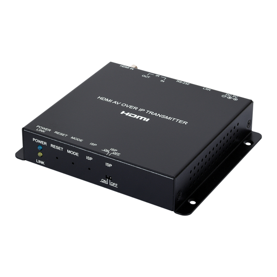
6. OPERATION CONTROLS AND FUNCTIONS 6.1 Front Panel POWER RESET MODE LINK POWER LED: This LED will flash while the unit is powering on and will illuminate solidly once it has finished booting and is ready for use. LINK LED: If the unit has no network connection this LED will not illuminate. -
Page 9: Rear Panel
6.2 Rear Panel DC 5V RS-232 HDMI IN DC 5V Port: Plug the 5V DC power adapter into this port and connect it to an AC wall outlet for power. LAN Port: Connect to a Gigabit Ethernet switch for signal extension to compatible Receiver(s), and to allow WebGUI/Telnet control. -
Page 10: Ir Cable Pinouts
6.3 IR Cable Pinouts IR Blaster IR Extender Cable Cable Power Infrared Infrared Power Not Used Ground 6.4 Serial Port Pinout and Defaults 3.5mm to DE-9 Adapter Cable Serial Port Default Settings Baud Rate 115200 Data Bits Parity Bits None Stop Bits Flow Control None... -
Page 11: Webgui Control
6.5 WebGUI Control • Accessing the WebGUI All major functions of the unit, including status, streaming method, streaming channel selection, output resolution, video wall configuration, EDID management, Ethernet settings, and reset/ firmware functions are controllable via multiple tabs in the WebGUI interface allowing for reasonably intuitive operation. -
Page 12: System Tab
6.5.1 System Tab The System tab contains four windows that provide access to firmware version information, a firmware update interface, utilities for rebooting and resetting the unit, basic EDID management, Telnet command entry, and a variety of statistics and information about the operational state of the unit. - Page 13 • Utilities The Utilities window allows users to reset/reboot the unit, configure the EDID behavior, and send Telnet commands to the unit. 1) Factory Default: Click this button to return the unit to its factory defaults. Note: Networking configuration details will not be reset. 2) Reboot: Click this button to reboot the unit. 3) Reset EDID to Default Value: If the EDID received from the primary Receiver unit (selected via a checkbox on the preferred Receiver in Multicast mode) has compatibility issues with the connected...
- Page 14 • Statistics The Statistics window shows all available information about the operational status of the unit, including current Host ID Name, SN, Ethernet information, MAC address, unicast/multicast mode, link status and mode.
-
Page 15: Video Wall Tab
6.5.2 Video Wall Tab The Video Wall tab allows the user to design, edit and manipulate a video wall system created using multiple Receiver units connected to identical displays. The bezel and video size of the displays being used, as well as the horizontal and vertical monitor count, is defined here. - Page 16 1) Bezel and Gap Compensation: This section of the Video Wall tab is used to define the physical dimensions of each display being used in the video wall. Accurate measurements are needed of the monitor’s outer frame (OW, OH) and the video screen (VW, VH). The measurements may be made using any unit of measurement (inches, mm, cm, etc.) as long as ALL measurements in the same wall are made using the exact same units and the numbers are...
- Page 17 2) Wall Size and Position Layout: This section of the Video Wall tab is used to define the number of displays used in the video wall as well as the location of the specific display within the video wall. A typical video wall consists of an equal number of horizontal and vertical monitors (for example: 2×2 or 3×3), however it is possible to create video walls using this system with a wider variety of...
- Page 18 3) Preferences: This section of the Video Wall tab provides additional controls over how the source video is displayed on the video wall as well as providing a drop down to determine which Receiver to apply changed settings to. Note: When setting up a new video wall, or changing the configuration of an existing one, remember to update the configuration of each Receiver in the system.
-
Page 19: Network Tab
6.5.3 Network Tab The Network tab provides controls over the Transmitter’s broadcast channel, IP configuration, and network broadcast mode. Changes made to the network settings will require a reboot of the unit. After clicking on “Apply” please follow the reboot instructions in the WebGUI. - Page 20 1) Channel Setup: Use the dropdown to select the broadcast channel for the Transmitter. All Receivers on the local network that are set to the same channel will receive video from this Transmitter. The available channel range is from 0 to 255. Note: Every Transmitter within the same local network must be assigned a different broadcast channel in order to avoid conflicts.
- Page 21 3) Casting Mode: Allows for the selection of the broadcasting mode used by the Transmitter. Click the “Apply” button to save changes made to the broadcasting mode. Note: Receivers must be set to the same mode as the Transmitter in order to receive video. ■...
-
Page 22: Functions Tab
6.5.4 Functions Tab The Functions tab provides control over the Transmitter’s maximum streaming bitrate, maximum frame rate, as well as serial control extension configuration. Changes made to these settings typically require a reboot of the unit. After clicking on “Apply” please follow the reboot instructions in the WebGUI, if necessary. - Page 23 ■ Maximum Framerate: Adjusting this slider will set the percentage of frames from the source video to encode (2% – 100%). This is ideal for reducing the bandwidth requirements of sources with high detail, but limited motion, such as power point presentations or information screens.
-
Page 24: Telnet Control
6.6 Telnet Control Before attempting to use Telnet control, please ensure that both the unit and the PC are connected to the same active networks. To Access the Command Line Interface (CLI) Click Start, type “cmd” in the search field, and Windows 7 press Enter. -
Page 25: Telnet Commands
6.7 Telnet Commands 6.7.1 System Commands COMMAND Description and Parameters help Show the full command list. help N1 Show help details about command N1. N1 = {Any command name} get_hardware_version Show the current hardware version. get_firmware_version Show the current firmware version. set_device_name N1... -
Page 26: Network Commands
6.7.2 Network Commands COMMAND Description and Parameters get_ipconfig Show the current IP configuration. set_ip_mode N1 Set the IP configuration mode. Available values for N1: [Static IP Mode] [DHCP Mode] [Auto IP Mode] get_ip_mode Show the current IP configuration mode. set_ip_address N1 Set the static IP address. -
Page 27: Discovery Service Commands
COMMAND Description and Parameters set_net_mode N1 Set the network broadcast mode. Available values for N1: [Unicast Mode] [Multicast Mode] get_net_mode Show the current network broadcast mode. set_jumbo_mtu N1 Enable/disable the jumbo frame MTU. Available values for N1: [Disabled] [Enabled] get_jumbo_mtu Show the jumbo frame MTU state. -
Page 28: Transmitter Specific Commands
6.7.4 Transmitter Specific Commands COMMAND Description and Parameters set_tx_channel N1 Set the VoIP transmission channel. N1 = 0 ~ 255 [VoIP channel] get_tx_channel Show the current VoIP transmission channel. set_ quality N1 Set the Tx picture quality mode. Available values for N1: [Graphic] [Video] get_ quality... - Page 29 COMMAND Description and Parameters set_frame_rate N1 Set the percentage of frames from the source video to encode. Available values for N1: [Disable] 1 ~ 60 [Frame Rate] set_vw_osd N1 {N2} Enable/disable the video wall OSD to display the Target Receiver number on the designated display.
- Page 30 COMMAND Description and Parameters set_vw_pos N1 N2 {N3} Set the display’s position within the video wall. (Cannot exceed the video wall’s horizontal and vertical display count.) N1 = 0 ~ 15 [Row] N2 = 0 ~ 15 [Column] N3 = 0 ~ 255 [Target Receiver {Optional}] Note: The Target Receiver number can be obtained by turning on the Video Wall OSD.
- Page 31 COMMAND Description and Parameters set_vw_vscale N1 {N2} Set the video wall display’s vertical zoom amount. N1 = 0 ~ 99999 [Zoom amount in 1 pixel units] N2 = 0 ~ 255 [Target Receiver {Optional}] Note: The Target Receiver number can be obtained by turning on the Video Wall OSD.
-
Page 32: Serial Commands
6.7.5 Serial Commands COMMAND Description and Parameters set_serial_baud N1 Set the serial baud rate. Available values for N1: [300] [600] [1200] [2400] [4800] [9600] [19200] [38400] [57600] [115200] get_serial_baud Show the current serial baud rate. set_serial_bits N1 Set the number of serial data bits. Available values for N1: [5 bits] [6 bits]... - Page 33 COMMAND Description and Parameters set_serial_parity N1 Set the serial parity bit. Available values for N1: [None] [Odd] [Even] get_serial_parity Show the current serial parity bit. set_serial_stop N1 Set the serial stop bits. Available values for N1: [1 stop bit] [2 stop bits] get_serial_stop...
-
Page 34: Connection Diagram
7. CONNECTION DIAGRAM Media Player 1.5m 60° Serial Control HDMI Input Device IR Input & Output 60° RS-232 Power Supply DC 5V RS-232 HDMI IN Network Switch Power Supply DC 5V HDMI OUT RS-232 RS-232 Serial Controlled IR Input & 60°... -
Page 35: Specifications
8. SPECIFICATIONS 8.1 Basic Specifications HDMI Bandwidth 225MHz/6.75Gbps Input Port 1×HDMI Output Port 1×LAN (RJ-45) Pass-through Ports 1×IR Extender (3.5mm) 1×IR Blaster (3.5mm) 1×RS-232 (3.5mm) IR Frequency 30 – 50kHz (30 – 60kHz under ideal conditions) Baud Rate Up to 115200 Power Supply 5V/2.6A DC (US/EU standards, CE/FCC/UL certified) -
Page 36: Video Specifications
8.2 Video Specifications Input Output Supported Resolutions (Hz) HDMI Streaming 720×400p@70/85 640×480p@60/72/75/85 720×480i@60 720×480p@60 720×576i@50 720×576p@50 800×600p@56/60/72/75/85 848×480p@60 1024×768p@60/70/75/85 1152×864p@75 1280×720p@50/60 ... -
Page 37: Audio Specifications
Input Output Supported Resolutions (Hz) HDMI Streaming 1920×1200p@60RB 2560×1440p@60RB 2560×1600p@60RB 2048×1080p@24/25/30 2048×1080p@50/60 3840×2160p@24/25/30 3840×2160p@50/60 (4:2:0) 3840×2160p@24, HDR10 3840×2160p@50/60 (4:2:0), HDR10 3840×2160p@50/60 ... -
Page 38: Cable Specifications
8.4 Cable Specifications 1080p 4K30 4K60 (4:4:4) (4:4:4) Cable Length 8-bit 12-bit 8-bit 8-bit High Speed HDMI Cable HDMI Input Ethernet Cable Cat.5e/6 100m Cat.6a/7 100m • 1080p (FHD Video) - Up to 1080p@60Hz, 12-bit color - Data rates lower than 5.3Gbps or below 225MHz TMDS clock •... -
Page 39: Acronyms
9. ACRONYMS ACRONYM COMPLETE TERM ASCII American Standard Code for Information Audio/Video Audio/Video Receiver or Recorder Cat.5e Enhanced Category 5 cable Cat.6 Category 6 cable Cat.6a Augmented Category 6 cable Cat.7 Category 7 cable Command-Line Interface DHCP Dynamic Host Configuration Protocol Digital Visual Interface EDID Extended Display Identification Data... - Page 40 ACRONYM COMPLETE TERM Phase Alternating Line Personal Computer SDTV Standard-Definition Television Transmission Control Protocol Video Graphics Array VLAN Virtual LAN VoIP Video over IP WUXGA (RB) Widescreen Ultra Extended Graphics Array (Reduced Blanking) Extended Graphics Array...
- Page 44 CYPRESS TECHNOLOGY CO., LTD. www.cypress.com.tw...
Need help?
Do you have a question about the CH-331H-TX and is the answer not in the manual?
Questions and answers