Table of Contents
Advertisement
Quick Links
Advertisement
Table of Contents

Related Manuals for Opticon MDI 1000


Summary of Contents for Opticon MDI 1000
- Page 1 MDI 1000 2D CMOS Imager Integration Guide...
- Page 2 In such cases, standard repair charges will apply. If a product is returned under warranty and no defect is found, standard repair charges will apply. Opticon Inc. assumes no liability for any direct, indirect, consequential or incidental damages arising out of use or inability to use both the hardware and software, even if Opticon has been informed about the possibility of such damages.
-
Page 3: Table Of Contents
Opticon MDI 1000 Integration Guide Contents 1. Introduction ..........................4 2. Integration Parameters ......................4 2.1. Exit Window Materials ..................... 4 2.2. Exit Window Design ......................5 3. Installation ..........................6 4. Cable Specifications ....................... 7 4.1. Connection between the Camera Module and the Decoder Board ......... 7 4.2. -
Page 4: Introduction
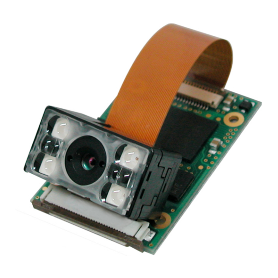
The MDI 1000 CMOS two-dimensional (2D) imager consists of the MSI 1000 camera module (referred to as the “camera module”) and the DBM 1000 decoder board developed specifically for the MDI 1000 (referred to as the “decoder board”). This guide provides instructions for installing the camera module and the decoder board. -
Page 5: Exit Window Design
Opticon MDI 1000 Integration Guide 2.2. Exit Window Design The exit window must be positioned to accommodate limitations of distance and inclination, as well as the range of the window itself. Design the layout within the range specified in the following diagram and associated table. -
Page 6: Installation
Opticon MDI 1000 Integration Guide 3. Installation When installing a camera module, use the tapping screw holes on the bottom surface. Do not over-tighten the screw. Only the bottom surface of the camera module should be attached to a chassis for installation. Keep enough clearance to avoid damage to the camera module in case the host instrument is dropped and damaged. -
Page 7: Cable Specifications
Opticon MDI 1000 Integration Guide 4. Cable Specifications Note: Connector mechanical drawings published by the manufacturer may be revised. Please refer to the latest mechanical drawings from the manufacturer for further details. 4.1. Connection between the Camera Module and the Decoder Board Connector: 54809-3375 (33 pins), manufactured by MOLEX Cable Length: 70 mm (max.) -
Page 8: Connection Between Decoder Board And Host
Opticon MDI 1000 Integration Guide 4.2. Connection between Decoder Board and Host Connector: 52437-3071 (30 pins), manufactured by MOLEX Cable Length: 70 mm (max.) Figure 4: Signal connection Figure 5: Connection between decoder board and host About FPC: • When producing the FPC, punch out the FPCs from the conductor side. -
Page 9: Handling Requirements
Opticon MDI 1000 Integration Guide 5. Handling Requirements Use anti-static measures such as a grounding strap before handling the scan engine in order to avoid damage to the electronic components from electrostatic discharge. Hold the scan engine only by the metal case. Do not touch the circuit board or the front side of the scan engine when handling it. -
Page 10: Mechanical Drawings
Opticon MDI 1000 Integration Guide 6. Mechanical Drawings 6.1. Camera Module Figure 6: Camera module Do not touch the circuitry when inserting the scan engine into the scanner. Only the black casing on the back side (0.9 mm thick) can touch the scanner case. -
Page 11: Decoder Board (Dbm 1000)
Opticon MDI 1000 Integration Guide 6.2. Decoder Board (DBM 1000) Figure 7: Decoder board...
Need help?
Do you have a question about the MDI 1000 and is the answer not in the manual?
Questions and answers