
Related Manuals for Fantasea Line FA6400


Summary of Contents for Fantasea Line FA6400
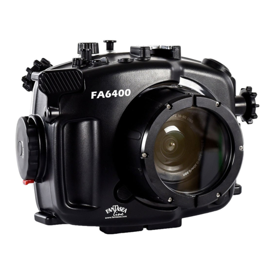
- Page 1 Fantasea Line FA6400 Housing (Cat. No. 1524) For Sony a6400 Instruction Manual FA6400 Housing Instruction Manual 20190416 ...
-
Page 2: Table Of Contents
& .......................... 42 LASH IDEO IGHTING .......................... 42 NTERCHANGEABLE ENS ORTS ............................. 43 ENS CCESSORIES ‐S .................... 43 HOE ONNECTOR FOR IGHTING CCESSORIES ............................ 43 ORT CCESSORIES CARE & MAINTENANCE .......................... 44 FANTASEA PRODUCT CONSUMER LIMITED WARRANTY ................ 45 FA6400 Housing Instruction Manual 20190416 ... -
Page 3: Disclaimer
DISCLAIMER While every effort has been made in order to ensure that the information included in this instruction manual is accurate and complete, no liability will be accepted for any errors or omissions. Fantasea Line reserves the right to change product specifications and features described herein at any time without prior notice. No part of this instruction manual may be copied, translated or reproduced without the prior written permission of Fantasea Line. Fantasea Line makes no warranties aside from limited product warranty as described at the end of this manual. INTRODUCTION Please read this manual carefully in order to properly operate the FA6400 IMPORTANT Housing. Store this manual in a safe place for further reference once you have NOTICE read it. The FA6400 Housing features a stylish and ergonomic design, specifically created for the Sony a6400 mirrorless digital camera. The FA6400 Housing is manufactured to the highest professional standards of function, style and durability. It is depth rated to 60m/200 feet and features ergonomically designed and labeled controls. The Fantasea FA6400 is the ultimate waterproof home for the Sony a6400 camera. The FA6400 Housing is ideal for outdoor and underwater photography. Underwater photographers can dive or snorkel and capture all the excitement of this fascinating world, while outdoor photographers also have the option of capturing the action of outdoor and water sports activities, such as paddle sports, sailing, boating, surfing, fishing, hunting, backpacking and camping. The FA6400 Housing is shock resistant and protects the camera from water, sand, dust, frost, impact, as well as other damaging elements and harmful occurrences. The FA6400 Housing was designed to be compatible with a complete accessory system, enabling photographers to enhance the quality of their images. FA6400 Housing Instruction Manual 20190416 ... -
Page 4: Features & Specifications
Access to all essential camera controls and functions with clearly labeled controls Shock resistant Double O‐ring protection for a perfect watertight seal M16 top port for a variety of connections, including HDMI or electronic strobe triggering bulkheads M16 rear port for Vacuum safety systems Hybrid Vacuum Safety System including moisture detector (optional) Special cold‐shoe mount for lighting accessories Double fiber optic cable port Removable anti‐glare hood for the LCD screen Easy and secure installation of camera Protective housing body cap Extended shutter release included for easy access when using housing tray and handles Interchangeable lens port and lens gear accessories are available, allowing for the use of a wide range of lenses Additional optional housing accessories are available Weight (without camera and lens port on land): 980g / 34.5 oz Weight (with camera and FML Flat Port on land): 1,595g / 56.2 oz Dimensions (without accessories): 20.5 x 14.5 x 15.5 cm \ 8 x 5.7 x 6.1 inch (W x D x H) Manufacturer’s warranty FA6400 Housing Instruction Manual 20190416 ... -
Page 5: Included In Package
INCLUDED IN PACKAGE (Corresponding numbered descriptions appear on the following page) 1 4 8 14 12 FA6400 Housing Instruction Manual 20190416 ... - Page 6 1. FA6400 Housing 8. Sticker for camera flash 2. Housing protective body cap 9. FML1 lens port opening tool 3. Nano fiber optic plug adaptor x 2 10. Screwdriver 4. Hand lanyard 11. Silica gel packs 5. Extended shutter release 12. Silicone grease 6. Anti‐glare hood for LCD screen 13. O‐ring remover 7. M16 port cap for Vacuum Valve 14. Spare back door O‐ring seal (if valve is removed) 15. Lens cloth Hybrid Vacuum Safety System Components (Optional) ...
-
Page 7: Identification Of Housing Parts
Optic Cable Port 4. Control Dial 3. C1 Button 2. On/Off 1. Shutter Release 11. Lens Dial 15. Latch Dial 14. Latch Dial Lock 13. Lanyard Loop 12. Interchangeable Lens Port System (Lens Ports are supplied separately) FA6400 Housing Instruction Manual 20190416 ... - Page 8 Note that the shutter release trigger can be replaced with an extended trigger (included in the package) for easier access when the housing is mounted on a tray & handle/arm system. For further instructions please refer to the section “Preparing the Housing”. 2. On/Off‐ Pushing this control activates the camera power switch button and turns the camera on/off. 3. C1 Button – Pushing this control activates the camera C1 (Custom 1) button. Various functions can be assigned to this button through the camera menu, providing access to favorite and most frequently used settings, thereby allowing quick operation based on your personal preferences and shooting habits. 4. Control Dial – Turn this dial to quickly adjust settings in each shooting mode, fine‐tune functions or browse through menu items. Note that the function of the control dial in Manual exposure shooting mode can be set through camera menus. 5. Non‐Functional Control – Pushing this control does not activate any of the camera buttons. It also doesn’t interfere with proper housing operation. Therefore, this control can be ignored while using the housing. 6. Mode Dial – Turn this dial to change shooting modes. 7. Flash Push‐Down Control – Pushing this control presses the built‐in flash back into the camera body after it has been popped‐up by using the Flash Pop‐Up control. Note that slight pressure should be applied when pushing this control in order to completely press the built‐in flash back into the camera body. The built‐in flash clicks once it has been properly pushed back down and this can also be verified by a dedicated marking on the camera LCD screen. 8. Cold‐Shoe Mount for Lighting Accessories‐ Enables mounting a flash, video light, torch or focus light on top of the housing by using a dedicated connector. For further information regarding such connectors, please visit the Fantasea website – www.fantasea.com FA6400 Housing Instruction Manual 20190416 ...
- Page 9 9. M16 Accessory Port – This port features a standard M16 thread hole and allows for optional connectors and accessories to be installed on the housing, including HDMI, vacuum valve or electronic strobe triggering bulkheads. For such accessories offered by Fantasea, please visit the Fantasea website – www.fantasea.com To remove the M16 port cover insert a coin into the dedicated slot featured on the cover and turn the cover counterclockwise until it can be safely removed. Store the cover for possible future use. Follow the instructions provided with the selected accessory product in order to install it inside the housing. Once the M16 port cover has been removed and replaced, it important to carry out the first dive with the housing empty (no camera installed inside) Important Notice in order to verify that the housing watertight seal has not been affected during the replacement. 10. Double Fiber Optic Cable Port – The 2 fiber optic cable ports with the inserted adaptors allow for easy attachment of up to 2 fiber optic cables to the housing. For further instructions, please refer to the section “Underwater Flashes & Strobes” in this manual. Note that the FA6400 Housing blocks the output of the built‐in flash and prevents it from being visible in images captured. This ensures that only the external strobes connected to the system illuminate the subject, thereby diminishing the effects of backscatter, as well as shadowing caused by housing lens port and lens accessories mounted on the housing. 11. Lens Dial – When a zoom lens is installed on the camera and a compatible lens gear is installed on the lens, turning this dial rotates the lens ring. For proper and smooth operation, it is recommended to install a Fantasea lens gear on the lens. For further instructions regarding installation of the lens gear, please refer to the instruction manual provided with your lens gear and/or lens port. For lens ports and lens gears compatible with your housing, please visit the Fantasea website – www.fantasea.com 12. Interchangeable Lens Port System – The housing features an FML interchangeable lens port system, which allows using a wide range of lenses underwater. The housing is compatible with any FML lens port, as well as other lens ports available in the market. For compatibility information, please visit the FA6400 Housing page on the Fantasea website – www.fantasea.com For further instructions regarding lens ports installation and removal please refer to the section “Installing and Removing Lens Ports”. ...
- Page 10 13. Lanyard Loops – The 3 lanyard loops featured on the housing (one loop at the bottom of the axis side of the housing and two top and bottom loops at the opposite side of the housing) are used to attach a Hand Lanyard or Hand Strap to the housing, as well as to secure accessories using snap cords or secure strings. 14. Latch Dial Lock – Ensures the secure dial doesn’t accidently open during the dive. For further instructions, please refer to the sections "Opening the Housing” and “Closing the Housing”. 15. Latch Dial – When locked fully into place, this dial ensures the housing is properly closed and watertight sealed. For further instructions, please refer to the sections "Opening the Housing” and “Closing the Housing”. Housing View #2 – Front ‐ Corresponding numbered descriptions are listed on the following page 16. Lens Port Lock 18. Lens Release Control 17. Tripod Mounting Screw Holes (bottom of housing) FA6400 Housing Instruction Manual 20190416 ...
- Page 11 16. Lens Port Lock – When set to the “lock” position, the Lens Port Lock ensures that the fully closed lens port doesn’t accidently open during the dive. When set to the “unlocked” position, the lens port can be removed and replaced. For further instructions regarding lens ports installation and removal please refer to the section “Installing and Removing Lens Ports”. The Lens Port Lock must not serve as an indication of a proper watertight seal and does not ensure that the lens port was properly installed on the Important Notice housing. For lens port installation guidelines and double check procedures, please refer to the section “Installing and Removing Lens Ports”. 17. Tripod Mounting Screw Holes – Enable mounting the housing on a tray or tray & handle system, thereby allowing for the addition of various image enhancement accessories. The 3 adjustment screw holes provide flexibility with respect to the choice of tray and the position of the housing mounted on it. This configuration also allows for the use of 2 set screws for the tray mount, thereby preventing any swiveling of the housing on the tray. Screws longer than 7mm should not be screwed into the housing Tripod Important Notice Mounting Plate, as they might damage the plate and housing. 18. Lens Release Control – Pushing this control presses the camera Lens Release button, which allows for unscrewing a lens and removing it from the camera while the camera is accommodated inside the housing. This is especially useful when using exceptionally large lenses which cannot be installed on the camera prior to inserting it into the housing. In such cases, the lens should be installed and removed through the lens port. For further instructions please refer to the section “Installing the Camera”. FA6400 Housing Instruction Manual 20190416 ...
- Page 12 29. Exposure 33. Drive Mode / Compensation / Self Timer / Image Index / Left Down 30. C2 Button / 32. Center Button Delete 31. Playback 19. Flash Pop‐Up – Pushing this control pops‐up the camera built‐in flash. Note that once the camera built‐in flash has been popped up, it can be pushed back into the camera body and disabled using the Flash Push‐Down control. 20. Vacuum Valve (optional) – Housings which the Fantasea Hybrid Vacuum Safety System is installed inside, feature the Vacuum Valve in this position. For instructions of use, please refer to the section “Fantasea Hybrid Vacuum Safety System”. Prior to opening a vacuumed housing, the vacuum should be released Important Notice using the Vacuum Valve. FA6400 Housing Instruction Manual 20190416 ...
- Page 13 In Playback mode, push this control to enlarge the reviewed image. 24. Fn (Function) ‐ Pushing this control activates the camera Fn (Function) button. In shooting mode, pushing this control allows recalling up to 12 registered functions. a. Push the Function control. b. Select the desired function by pushing the up/down/left/right sides of the control wheel. c. Select the setting value by turning the control wheel. d. Some functions can be fine‐tuned using the control dial. e. Push the center button to confirm the selection. f. To adjust settings from the dedicated settings screen, select the desired function (step b), push the center button and adjust settings on the dedicated settings screen. In playback mode, push this control to send the reviewed image to a smartphone. 25. Movie Recording – Pushing this control activates the camera Movie button and starts/stops recording a video. 26. Display / Up ‐ Pushing this control activates the camera Display / Up button. 27. ISO / Right ‐ Pushing this control activates the camera ISO / Right button. 28. Control Wheel ‐ Rotating this wheel operates the camera control wheel, thereby enabling to alter exposure values, navigate through menus and other functions assigned to the control wheel. 29. Exposure Compensation / Image Index / Down – Pushing this control activates the camera Exposure Compensation / Image Index / Down button. FA6400 Housing Instruction Manual 20190416 ...
- Page 14 30. C2 Button / Delete – In shooting mode, push this control to activate the C2 button. Various functions can be assigned to this button through the camera menu, providing access to favorite and most frequently used settings, thereby allowing quick operation based on your personal preferences and shooting habits. In playback mode, push this control to delete images. 31. Playback – Pushing this control allows entering the playback mode and reviewing images or videos stored on the memory card. 32. Center Button ‐ Pushing this control activates the camera center button, which is mainly used to confirm selections. 33. Drive Mode / Self Timer / Left – Pushing this control activates the camera drive mode / self timer / left button. 34. Anti‐Glare Hood Rails– The anti‐glare hood enables a better view of the LCD screen when shooting in bright conditions. It can be removed and installed during the dive. For further instructions, please refer to the section “Preparing the Housing”. Housing View #4 – Front Door Interior ‐ Corresponding numbered descriptions are found on the following page 37. LED Trigger Ports 36. Lens Port Lock Internal View 35. Camera Tray Port FA6400 Housing Instruction Manual 20190416 ...
- Page 15 35. Camera Tray Port – The camera tray allows for easy installation of the camera inside the housing and ensures the camera is positioned securely and steadily during the dive. Note that the camera battery compartment can be opened when the camera is installed on the tray, allowing for easy and quick battery and memory card replacement without having to remove the camera from the tray. The camera tray port secures the camera tray and ensures the camera is positioned firmly and tightly inside the housing, allowing for smooth operation in all depths. For further instructions, please refer to the section “Installing the Camera”. Prior to mounting the camera on the tray, the camera LCD screen should Important Notice be tilted upward by pulling its bottom part outward in order to allow proper attachment to the tray. 36. Lens Port Lock (Internal View) – After a lens port has been installed and the lens port lock has been locked, it is recommended to examine the lock inside the housing to confirm that the port has been properly installed and the port lock has been completely locked. For further instructions, please refer to the section “Installing and Removing Lens Ports”. 37. LED Trigger Ports – Designed to allow the use of an LED Flash Trigger inside the housing. The LED Flash Trigger is a useful accessory when making use of slave strobes connected to the housing with fiber optic cables. It attaches to the camera hot‐shoe on one end and to the two LED Trigger Ports on the other end. When an image is captured, the device LEDs installed inside the LED Trigger Ports trigger the slave strobe without activating the camera built‐in flash. This spares camera battery consumption and also prevents the built‐in flash recycle time from limiting continuous shooting. For LED Trigger Ports available, please visit the Fantasea website – www.fantasea.com FA6400 Housing Instruction Manual 20190416 ...
-
Page 16: Setting Up The Housing
PREPARING THE CAMERA 1. Install a (preferably empty) memory card (32 GB+ capacity recommended) and a fully charged battery inside the camera. 2. Remove the camera strap from the camera if one was installed. 3. Note that there is no need to remove the eyepiece rubber cup, as it doesn’t interfere with installation or operation of camera inside the housing. 4. Install the selected lens on the camera and remove the lens cap from lens. 5. If making use of a lens gear and/or light shading pad, install them on the lens following the instructions provided with these accessories. 6. Built‐in Flash Push Down Reminder Sticker – Attach the Prior to installing the camera inside the sticker here housing, the camera built‐in flash must be pushed into the camera body. Any attempt of installing the camera into the housing with the flash popped‐up might damage the camera and the housing and will Image #1 necessarily interfere with a proper watertight seal of the housing. A dedicated warning sticker was designed for the purpose of reminding you to push the built‐in flash into the camera body prior to installing it into the housing. It is recommended to attach this sticker on the camera, at the back of the popped–up built‐in flash (image #1). 7. Monitor/Finder setting ‐ The a6400 camera is equipped with a sensor which is capable of automatically switching the display between the electronic viewfinder and the LCD monitor. Default camera settings activate this sensor and enable the automatic switch. In order to ensure that the LCD monitor doesn’t turn off automatically underwater, it is important to set the FA6400 Housing Instruction Manual 20190416 ... -
Page 17: When Using The Housing For The First Time
WHEN USING THE HOUSING FOR THE FIRST TIME 1. Peel the transparent plastic screen protector off the back door exterior of the housing. 2. Install the hand lanyard on the housing by inserting it through the lanyard loop on the bottom right of the housing (facing from back), then pulling it through itself and testing it in order to make sure it is secure (image #2). 3. Open the housing (see section “Opening the Housing”) and remove the anti‐glare hood out Image #2 of the housing. Secure the anti‐glare hood to the housing by tying its secure string around the lanyard loop at the bottom left side of the housing. Install the anti‐glare hood over the anti‐glare hood rails at the back of the housing. First install the anti‐glare hood over the top rail (image #3) and then gently and carefully stretch it downwards to install it on the bottom rail, making sure it’s sitting securely on both upper and lower rails (image #4). Image #3 Image #4 4. Installing the Extended Shutter Trigger – When mounting the housing on a tray & handle or tray & arm system, you might consider replacing the shutter release trigger with the extended replacement trigger included in the package. The extended trigger provides easier access to the shutter release when an arm or handle are mounted next to the housing. To replace the shutter release trigger with the extended one included, complete the following steps: FA6400 Housing Instruction Manual 20190416 ... - Page 18 Using the screwdriver included in the kit, remove the screw that secures the shutter release trigger (image #6). Store it safely, although a spare screw is included in the kit. Image #6 Image #5 c. Remove the trigger by pulling it out and away from the housing (image #7). Note that once the trigger has been removed, the control metal shaft can be accidently pushed in, resulting with the spring in the interior of the control slightly moving out of place and thus disabling proper operation of the control. Therefore, make sure not to push the control shaft into the housing. Store the removed trigger for possible future use. d. Install the replacement extended trigger on the exposed metal shaft of the control by aligning the protrusion featured on the control with the shape of the shaft (image #8). Image #8 Image #7 e. Using your finger, apply slight counterforce on the control inside the housing to prevent the shaft from being pushed into the housing while installing the replacement extended trigger. FA6400 Housing Instruction Manual 20190416 ...
-
Page 19: Installing M16 Port Accessories
Note that if encountering problems with Image #9 operation of the control upon completing the replacement, the spring featured on the interior of the control might have accidently moved out of place. This being the case, remove the shutter release trigger again, gently push the metal shaft of the control towards the housing, rearrange the spring inside the housing so it sits entirely below the black plastic lever of the control (image #10), push the control metal shaft Image #10 back out and reinstall the trigger. INSTALLING M16 PORT ACCESSORIES The port above the housing axis features a standard M16 thread hole and allows for optional connectors and accessories to be installed on the housing, including HDMI or electronic strobe triggering bulkheads. For such accessories offered by Fantasea, please visit the Fantasea website – www.fantasea.com 1. To remove the M16 port cover insert a coin into the dedicated slot featured on the cover and turn the cover counterclockwise until it can be safely removed (images #11 and 12). Image #11 Image #12 FA6400 Housing Instruction Manual 20190416 ... -
Page 20: Mounting And Removing Lens Ports
Important carry out the first dive with the housing empty (no camera installed inside) in order to verify that the housing watertight seal has not been Note affected during the replacement MOUNTING AND REMOVING LENS PORTS The housing features an FML interchangeable lens port system, which allows using a wide range of lenses underwater. The housing is compatible with any FML lens port, as well as other lens ports available in the market. For compatibility information and lens ports available, please visit the Fantasea website – www.fantasea.com 1. Mounting a lens port on the housing: If possible, it is recommended to mount the lens port on the housing prior to installing the camera inside. If using exceptionally large lenses which cannot be installed on the camera prior to inserting it into the housing, the camera and lens can be installed inside the housing prior to mounting the lens port. Please refer to section “Installing the Camera” ‐ step 18. For smooth installation and removal of the lens port, it is recommended to apply a slight amount of Fantasea Silicone Grease over the lens port O‐ring prior to installing it on the housing. Turn the lens port lock rightwards, so it’s seated at the “UNLOCK” position (image #13). Remove the body cap from the Image #13 housing lens port hole. Store for future use. FA6400 Housing Instruction Manual 20190416 ... - Page 21 Carefully push the lens port against the housing until it’s fully inserted inside the port hole. Examine the lens port from all directions to make sure it was Image #14 evenly inserted. g. While still applying slight pressure on the lens port against the housing, turn the lens port clockwise until it reaches a point where it can’t be turned any farther. The white marking on the lens port should now be aligned with the lock engraved on the housing (image #15). h. To secure the lens port in place, turn the lens port lock leftwards, so it’s seated at the “LOCK” position (image #16). Image #15 Image #16 i. Once the lens port has been installed and the lens port lock has been locked, it is recommended to open the housing and examine the lock from the inside. If the port has been properly installed and the port lock has been completely locked, the lock is positioned in between lens port “teeth” and blocks them from turning (image #17 on the following page). FA6400 Housing Instruction Manual 20190416 ...
- Page 22 Image #17 housing and encountering resistance when attempting to push the port against the housing, simply turn the port a bit until reaching the point where the port can be inserted completely into the housing, even if housing and port markings are no longer aligned. Continue with steps “h” and “i” above to make sure the port has been properly installed and locked. Once a lens port has been mounted on the housing, it is important to test Important the housing empty (no camera installed inside) in a body of water in order to verify that the housing watertight seal has not been affected during lens Note port installation. 2. Removing a lens port from the housing: a. Make sure to dry the housing exterior prior to opening the lens port in order to avoid water coming in contact with the camera or lens once the lens port is removed. b. If the lens cap is secured to the housing with a snap cord or secure string, detach the string or remove the lens cap. c. Turn the lens port lock rightwards, so it’s seated at the “UNLOCK” position (image #13). d. Hold the housing in one hand and the lens port with the other. It is recommended to hold the lens port using a silicone pad for maximum friction. Turn the lens port counterclockwise until reaching a point where it can’t be turned any farther. The white marking on the lens port should now be aligned with the white marking on the housing (image #14). e. If encountering resistance when attempting to turn the lens port counterclockwise as a result of significant pressure changes, it is recommended to use the FML1 lens port opening tool. Insert the lens port opening tool into the dedicated slots found on the front ring of the lens port (image #18 on the following page). Use the lens port opening tool to turn the lens counterclockwise while carefully applying slight pressure FA6400 Housing Instruction Manual 20190416 ...
-
Page 23: Opening The Housing
Separate the lens port from the housing by pulling it out and away from the housing. g. Note that it is recommended to store the lens port separated from the housing during transportation and storage. h. To protect the housing during storage and transportation, it is recommended to mount the body Image #18 cap on the housing lens port hole and secure it by turning it clockwise. OPENING THE HOUSING Prior to opening a vacuumed housing, the vacuum should be released using the Vacuum Valve. For further instructions, please refer to the Important Notice section “Fantasea Hybrid Vacuum Safety System”. 1. Pull the small red tab located at the bottom of the latch dial outwards (up and away from the housing), as indicated by the arrow direction (image #19 on the following page). There is no need to apply any force. 2. While holding the lock dial up, turn the latch dial counterclockwise until the red latch tab is located at the top of the latch and cannot be turned any farther (image #20 on the following page). There is no need to apply any force. FA6400 Housing Instruction Manual 20190416 ... -
Page 24: Checking The O-Ring
Image #19 Image #20 3. Carefully open the back side of the housing. CHECKING THE O‐RING 1. Prior to each closure of the housing, the back door black O‐ring should be visually inspected. If there is any debris present, including dirt, sand, dust, hair or any other matter, it must be cleaned to ensure a proper watertight seal. 2. In order to clean the black O‐ring, first remove it from the housing: a. Insert the O‐ring remover between the black O‐ring and the groove it is seated in (image #21). b. Slip the tip of the inserted O‐ring remover below the black O‐ring, while making sure the O‐ring doesn’t get damaged (image #22). c. Carefully hold the O‐ring with your fingertips in order to remove it from the groove. Image #21 Image #22 FA6400 Housing Instruction Manual 20190416 ... -
Page 25: Installing The Camera
3. Cleaning the O‐ring is a simple matter of wiping it with a damp, soft cloth to remove the foreign matter. Be careful the cloth you use does not leave any of its own material behind as this can also affect the effectiveness of the seal. 4. Apply a slight layer of Fantasea Silicone Grease on the black O‐ring. Please note that the amount of lubrication required on the O‐ring is only enough to allow it to slip into place without friction, so it does not twist or become dislodged. More grease is not necessarily better, and in some cases might interfere with the watertight seal of the housing. 5. When replacing the O‐ring, place it back into the groove starting at one corner and gently pressing it into the groove all around the housing until it is all seated in the groove and no part of it is sticking up or out of the groove. 6. The white O‐ring featured on the back side of the front door should be visually inspected prior to each dive. If there is any debris present, gently wipe the area with a soft microfiber cloth in order to cleanse it. 7. The white O‐ring featured on the back side of the front door shouldn’t be removed unless it’s damaged. INSTALLING THE CAMERA Since the FA6400 Housing is specifically designed for the Sony a6400 mirrorless digital camera, installing the camera in the housing is quite simple. 1. If possible, it is recommended to install the camera inside the housing after the lens port has been mounted on the housing. If using exceptionally large lenses which cannot be installed on the camera prior to inserting it into the housing since the lens is too large be inserted through the housing lens port hole, the lens port should be mounted on the housing only after the camera and lens have been inserted. In such cases, please follow the instructions provided in step 18 below for camera installation. 2. Open the housing (see section “Opening the Housing”). 3. Prepare the camera following the instructions provided in the section “Preparing the Camera”. 4. Turn the camera tray port lock rightwards, to the “UNLOCK” position (image #23). ... - Page 26 (image #24). After camera installation, the LCD screen should be realigned for a clear view. 7. Mount the camera on the tray by installing the mounting screw featured on the tray into the mounting screw hole found at the bottom of the camera (image #25). Make sure to follow the diagram printed on the tray and install the camera facing forward. Once the screw has been tightened, make sure that the camera is positioned steadily on the tray. Image #24 8. Note that the camera battery compartment can be opened when the camera is installed on the tray, allowing for easy and quick battery and memory card replacement without having to remove the camera from the tray. 9. Prior to installing the tray and camera into the housing: a. Make sure that the built‐in flash is pushed down into the camera body. Any attempt of installing the camera into the housing with the flash popped‐ Image #25 up might damage the camera and the housing and will necessarily interfere with a proper watertight seal of the housing. b. Make sure the camera is turned off and that the housing On/Off control is set at the “Off” position as well. c. Turn the AEL/AF/MF control on both the camera and the housing to AEL. Failing to do so will disable the control once the camera is accommodated inside the housing. d. Turn the Mode Dial so the same shooting mode is selected and aligned with the white mark on the left of the wheel on both the camera and housing (image #26 on the following page). This will allow for the camera and housing mode dials to be aligned, so the housing mode dial will indicate the proper mode selected by the camera dial. FA6400 Housing Instruction Manual 20190416 ...
- Page 27 Image #26 e. Pull the housing Mode Dial up and away from the housing to allow for smooth installation of the camera (image #27). 10. Install the tray with camera into the camera tray port by holding the tray parallel to the housing, aligning the rods of the tray with those featured on the tray port and sliding the tray all the way in (image #28). 11. Turn the camera tray port lock leftwards, to the “LOCK” Image #27 position (image #29). Make sure that the tray was properly installed and locked by gently trying to pull it out. 12. Realign the camera LCD screen by slightly pushing its bottom inwards and pulling its top outwards until it reaches a complete vertical angle (image #30 on the following page). 13. If making use of any electronic triggers, such as a LED Flash Trigger or an electronic strobe bulkhead, attach the accessory to the camera Image #28 hot‐shoe connection. 14. If inserting a silica gel pack inside the housing in order to prevent moisture, it is best to insert it on the left side of the camera and to attach it with tape to the housing wall, where it doesn’t interfere with proper housing operation. It is Image #29 important to make sure that the silica gel pack doesn’t stick out, or else it might interfere with the watertight seal of the housing. FA6400 Housing Instruction Manual 20190416 ...
- Page 28 17. When using an exceptionally large lens, you might find that the lens cannot be installed on the camera prior to inserting it into the housing, as the lens is too large to be fully inserted inside the housing port hole. In such Image #30 cases, the lens should be installed on the camera after the camera has been inserted into the housing. The lens port should be mounted on the housing only after the lens has been installed. Follow the steps below: a. Prepare the housing as described in the section “Preparing the Housing”, only without mounting the lens port. b. Prepare the camera as described in the section “Preparing the Camera”, only without installing the lens on the camera. c. Follow the instructions provided above in this section to install the camera (without the lens) inside the housing. d. Once the camera is installed, the lens can be mounted on the camera through the housing lens port hole (image #31). Align the white dot on the lens with the one marked on the camera, attach the lens to the camera and turn it clockwise until it clicks. e. Mount the lens port on the housing (see section “Installing and Removing Lens Ports”). f. To remove the camera and lens from the housing, follow the instructions provided at the end of the section “Removing the Image #31 Camera from the Housing”. FA6400 Housing Instruction Manual 20190416 ...
-
Page 29: Closing The Housing
3. Turn the secure dial clockwise till the lock dial clicks. The small red tab should then be pointed towards the bottom of the housing (image #33). 4. Gently try pulling the back door away from the front door. If the housing is properly closed, it should be impossible to open the back door. Image #32 Image #33 5. Visually inspect the black O‐ring through the transparent back door for proper closure. Make sure it isn’t twisted or out of the groove and that no foreign matter has been caught in the seal, such as secure lines, sand, grit, hairs or any other foreign substance. 6. Test housing control buttons to make sure that the camera was properly installed inside the housing and that nothing interferes with normal operation of the camera. It is recommended to take a few images once the camera has been installed inside the housing and prior to the dive in order to ensure proper operation. 7. Prior to diving with the housing, submerge it in a shallow tub of water or rinse tank. Carefully look at the housing to make sure no bubbles are escaping from it, no water is entering and the moisture alarm (if installed inside the housing) doesn’t beep. 8. If a Vacuum Safety System is installed inside the housing, perform a pre‐dive check to confirm the watertight seal of the housing. See “Hybrid Vacuum Safety System” section for further instructions. FA6400 Housing Instruction Manual 20190416 ... -
Page 30: Removing The Ca Mera From The Housing
2. Open the housing as described in the section “Opening the Housing”. Take sufficient care that no water drips from your hair and body onto the housing and camera. 3. If an accessory is connected to the camera hot‐shoe, disconnect it to allow for safe camera removal. 4. Turn the camera tray port lock rightwards, to the “UNLOCK” position (image #34). 5. Remove the camera tray from its port by gently sliding it out. 6. Loosen the screw that secures the camera to the tray. 7. Remove the camera from the tray. 8. Reinstall the tray inside the housing to avoid losing it. Image #34 18. When using an exceptionally large lens which cannot be removed from the housing with the camera, as it’s too large to pass through the housing lens port hole, the lens should be dismounted prior to removing the camera from the housing. Follow the steps below: a. After use, thoroughly rinse the housing fresh water as described in step 1 above. b. Remove the lens port from the housing (see section “Installing and Removing Lens Ports”). c. Detach the lens from the camera. With one hand, push the “Lens Release Control”. With the other, grab the lens and turn it counterclockwise until it cannot be turned any farther (image #35 on the following page). Once the lens has been turned, it can be removed from the camera by pulling it away from the camera body. d. Remove the camera from the housing by following steps 2‐8 above. FA6400 Housing Instruction Manual 20190416 ... - Page 31 Image #35 FA6400 Housing Instruction Manual 20190416 ...
-
Page 32: Fantasea Hybrid Vacuum Safety System
FANTASEA HYBRID VACUUM SAFETY SYSTEM The Fantasea Hybrid Vacuum Safety System is an optional pre‐dive vacuum test and leak detector safety system. The system allows confirming the watertight seal of the housing prior to the dive using the vacuum system and monitoring the housing seal during the dive using the moisture detector. Follow the instructions below to safely charge and use the system. 1. Instructions provided below refer to housings which the system is already installed in. In case of installing a new vacuum system that was separately purchased, please refer to the installation guide included with the vacuum system. Important Notice 2. Use of the Hybrid Vacuum Safety System must not replace any of the other safety measures conducted in order to ensure a complete watertight seal of the housing before and during the dive. Identification of System Parts (Housing Back Door Interior) Main PC Board Signal Board LED Indicator Moisture Sensor FA6400 Housing Instruction Manual 20190416 ... - Page 33 Charging the Unit 1. Turn the unit on using the power switch featured on the Signal Board. 2. The LED Indicator will start flashing blue: a. Slow flashing (approx. 1 flash per second) indicates a charged battery. b. Rapid flashing (approx. 4 flashes per second) indicates low battery. 3. To charge the unit, connect it to a USB charger using a standard Micro‐USB cable Image #36 (not included). Note that it is best using an android phone charger unit for this purpose. 4. Connect the micro‐USB end of the cable to the Micro‐USB port on the Signal Board (image #36). Connect the other end of the cable to a USB port or USB charger. 5. The unit should start charging and the LED Indicator should start flashing green. 6. Make sure to keep the unit turned on during charging. 7. When charging is complete, the LED Indicator stops flashing and remains green. 8. Disconnect the cable and turn the unit off using the power switch on the Signal Board to save battery power. If the unit is left turned on, the battery will drain within a few days. 9. During charging, keep the charger away from highly flammable materials or products and never leave the charger unattended when in use. 10. Never apply any type of pressure on the battery, expose it to direct heat or chemicals. 11. Battery must not be charged in temperatures below freezing or above 50°C (122°F). FA6400 Housing Instruction Manual 20190416 ...
- Page 34 During long periods of storage, the unit should be stored partially charged in a cool and dry area. Performing a Pre‐Dive Check 1. Prior to closing the housing, turn the unit on using the power switch on the Signal Board. The switch should be pushed leftwards in order for the unit to be turned on. Make sure the unit is properly charged and that the LED indicator flashes slowly (approx. 1 flash per second). 2. Lock the housing, lens port and all other accessories which their installation might have an effect on the watertight seal of the housing. Camera should be turned off prior to the pre‐dive check. The housing should be completely set up for the dive prior to performing the vacuum pre‐dive check. Any modifications carried out on the housing after the Important Notice pre‐dive test has been completed necessarily turn the check results irrelevant and require performing an additional pre‐dive check. 3. Remove the protective cap from the Vacuum Valve by gently turning it counterclockwise and screwing it out (image #37). Make sure you’re only removing the protective cap when turning it, rather than the complete valve. If the valve screws out together with its cap, use the wrench included in order to tighten the valve inside the port. This will allow for easy and safe removal of the protective cap when screwed out. Image #37 FA6400 Housing Instruction Manual 20190416 ...
- Page 35 6. Connect the Vacuum Pump to the Vacuum Valve by gently pushing the exposed valve all the way into the Rubber Fitting of the pump. 7. Use the Vacuum Pump to pump air out of the housing by gently and steadily pulling and releasing its handle (image #39). While doing so, carefully watch the LED Indicator through Image #39 the back door of the housing to monitor the air pressure inside the housing as it progresses through the following stages: a. Yellow flashing rapidly – air pressure has started to drop. Continue pumping. b. Yellow flashing slowly – air pressure continues to drop. Turn counterclockwise Continue pumping. Note that that pumping should be and pull out carried out at a slower pace as the Indicator LED flashes slower and air pressure approaches the optimal level. c. Steady yellow (no flashing) – air pressure has reached the optimal level. Stop pumping and allow the analysis to begin. d. Yellow & Red flashing alternately – indicates over pumping and under pressure inside the housing. Stop pumping and carefully release a bit of the vacuum by turning the Vacuum Image #40 Release Tip counterclockwise and pulling it out (image #40) until the LED Indicator turns steady yellow, indicating a proper pressure for the check. If the LED Indicator starts flashing yellow again, overpressure has been produced inside the housing due to excessive vacuum release. Use the Vacuum Pump to extract air again until the LED indicator turns steady yellow. 8. The analysis beings once the LED Indicator turns steady yellow. Carefully disconnect the Vacuum Pump from the Vacuum Valve and reinstall the Protective Cap over the valve. FA6400 Housing Instruction Manual 20190416 ...
- Page 36 Yellow flashing ‐ Use the Vacuum Pump to extract air again until the LED indicator turns steady yellow. b. Red and Green flashing ‐ Release a bit of the vacuum by turning the Vacuum Release Tip counterclockwise and pulling it out (image #40) until the LED Indicator turns steady yellow. 12. In case of a significant air leakage detected anytime during the process, the LED Indicator will turn flashing red. Pre‐Dive Check LED Indicator Diagram Flashing Steady Flashing Flashing Yellow Yellow Red/Yellow Red 4‐min. Vacuum Release Vacuum Continue Inspect housing Analysis in progress with Valve Lock for source of Pumping leakage Flashing Red = Flashing Green = Housing Failed Housing ready to Check dive FA6400 Housing Instruction Manual 20190416 ...
- Page 37 Dive with the housing without detaching or attaching any accessories which their installation might have an effect on the watertight seal of the housing. The Vacuum Safety System was designed to test and confirm the watertight seal of the housing prior to the dive only. Monitoring the watertight seal of the housing during the dive is carried out using Important Notice the Moisture Detector included in the system. See “Moisture Detector” section below for further information. 14. After the dive: a. Prior to opening the housing, make sure to completely release the vacuum by turning the Vacuum Release Tip counterclockwise and pulling it out (image #40). This prevents stressing the housing Latch Dial. b. Turn the system off using the power switch on the Signal Board to save battery life. Moisture Detector The Moisture Detector allows monitoring the watertight seal of the housing during the dive. Moisture detectors are very sensitive, so whenever moisture is detected by the sensor, the LED Indicator starts flashing red and a warning alarm starts beeping, thereby alerting of a possible leak. You can test the Moisture Detector (image #41) by placing a wet finger over the moisture sensor unit at the bottom of the housing. In order to silence the alarm after it starts beeping: a. Gently wipe the Moisture Sensor unit with a soft dry cloth in order to dry it off. b. Switch the Vacuum System off using the power switch on the Signal Board. Image #41 FA6400 Housing Instruction Manual 20190416 ...
- Page 38 Remove the Vacuum Valve from its port using the Image #42 wrench. Fit the wrench around the edges of the Vacuum Valve base and turn it counterclockwise until the valve has been completely unscrewed. b. Visually inspect the O‐ring featured at the base of the Vacuum Valve. If there is any debris present, including dirt, sand, dust, hair or any other matter, it must be cleaned to ensure a proper watertight seal. c. In order to clean the O‐ring, first remove it from the Vacuum Valve. d. Cleaning the O‐ring is a simple matter of wiping it with a damp, soft cloth to remove the foreign matter. Be careful the cloth you use does not leave any of its own material behind as this can also affect the effectiveness of the seal. e. Apply a slight layer of Fantasea Silicone Grease on the O‐ring. Note that the amount of lubrication required on the O‐ring is only enough to allow it to slip into place without friction, so it does not twist or become dislodged. More grease is not necessarily better, and in some cases might interfere with the watertight seal of the housing. f. Reinstall the O‐ring and then reinstall the Vacuum Valve using the wrench. g. Confirm that the housing watertight seal hasn’t been interfered using the vacuum pre‐ dive check prior to diving with the housing again. 3. Never soak or wash the interior of the housing with water. This will cause irreparable damage to all Hybrid Vacuum Safety System electronic components! FA6400 Housing Instruction Manual 20190416 ...
- Page 39 Vacuum Valve Removal 1. In case of removing the Vacuum Valve for whatever reason, follow the steps below: a. Remove the Vacuum Valve from its port using the wrench. Fit the wrench around the edges of the Vacuum Valve base and turn it counterclockwise until the valve has been completely unscrewed. b. Install the M16 Cap included in the package on the Vacuum Valve port by screwing it all the way in (image #43). Image #43 1. Once the Vacuum Valve has been removed and an M16 port cap has been installed on the port, it important to carry out the first dive with the housing empty (no camera installed inside) in order to verify that the housing watertight seal has not been affected during the replacement. Important Notices 2. The Vacuum Valve port was designed to accommodate the Vacuum Valve only and any other components should not be installed on this port. For installation of electronic strobe triggering bulkheads, HDMI connectors or any other accessories, use the standard M16 Port found at the top left corner of the housing. FA6400 Housing Instruction Manual 20190416 ...
-
Page 40: Optional Accessories
OPTIONAL ACCESSORIES FOR THE FULL SELECTION OF FANTASEA ACCESSORIES COMPATIBLE WITH THE FA6400 HOUSING, PLEASE REFER TO THE FANTASEA WEBSITE – WWW.FANTASEA.COM UNDERWATER FLASHES & STROBES Underwater strobes (external flashes) were designed to improve the color, lighting and quality of your underwater images. Since light and color are absorbed by water, using a strobe is recommended in all depths, during daylight and night dives. Note that the FA6400 Housing blocks the output of the built‐in flash and prevents it from being visible in images captured. This ensures that only the external strobes connected to the system illuminate the subject, thereby diminishing the effects of backscatter, as well as shadowing caused by housing lens port and lens accessories mounted on the housing. The FA6400 Housing can be used both with underwater slave flashes and electronic strobes. For a full selection of external strobes available, please visit the Fantasea website – www.fantasea.com Slave Flashes Slave flashes feature a slave sensor which triggers the external flash to fire in sync with the camera built‐in flash. A fiber optic cable connects between the camera housing and the slave flash. The output of the camera built‐in flash (or LED flash trigger if using one) is transmitted through the fiber optic cable to the slave sensor of the slave flash, which is then triggered to fire in sync with the camera. Attaching Fiber Optic Cables to the Housing The FA6400 Housing features 2 fiber optic cable ports which allow for easy attachment of up to 2 fiber optic cables to the housing. These fiber optic cable ports were designed to accommodate the type of adaptors included with the housing (see image #44). If the fiber optic cable you have features a different type of adaptor, remove this adaptor from the end of the cable and use the adaptors included with the FA6400 Housing instead. Image #44 To attach a fiber optic cable to the housing, first remove the adaptor from the housing fiber optic cable port by pulling it out using your fingers or the aid of a small needle nose set of pliers (image #45 on the following page). Make sure not to damage the fiber optic cable. FA6400 Housing Instruction Manual 20190416 ... - Page 41 Insert the exposed end of the fiber optic cable into the small hole of the adaptor unit, starting from the end that features a screw and pushing it towards the end that features an O‐ring (image #46), until the fiber optic cable reaches the end of the adaptor, which can be verified by looking from the other side of the adaptor. The fiber optic cable should be extending out no more than 1mm. Image #46 Image #45 Use the screwdriver included in order to tighten the screw on the adaptor (image #47). Tighten it enough to stabilize the fiber optic cable inside the adaptor, but don't tighten it too strongly. Tightening the screw too much might damage the fiber optic cable. Once the fiber optic cable has been installed inside the adaptor, install the adaptor back to its port. It’s recommended to apply some Fantasea Silicone Grease on the small o‐rings of these adaptors, so they can be installed and removed more easily. Insert the adaptor with the end featuring the screw pointing out of the housing and then push it all the way into the port (image #48). Image #47 Image #48 FA6400 Housing Instruction Manual 20190416 ...
-
Page 42: Led Flash Triggers
9. Follow the instructions in your strobe manual on how to synchronize your camera with the external flash and to select the proper pre‐flash program for your camera. It is recommended to test the synchronization when photographing opposite a mirror. In this case, the output of the slave flash should be visible in the test shot taken. 10. Note that an optional LED Flash Trigger can be used to trigger the slave flash instead of being triggered by the camera built‐in flash. See “Led Flash Trigger” section for further information. Electronic Strobes Electronic strobes can be attached to the housing using electronic sync cords. These sync cord connect to the housing electronic strobe bulkhead (separately purchased), which connects to the camera hot‐shoe. The FA6400 Housing features an M16 Accessory Port, which allows for the installation of an electronic strobe bulkhead in the housing. Note that such a bulkhead should be separately purchased. For further information, visit our website – www.fantasea.com LED FLASH TRIGGERS The FA6400 Housing features two dedicated ports inside the housing, which were designed to allow the use of an optional LED Flash Trigger. The LED Flash Trigger is a useful accessory when making use of slave flashes connected to the housing with fiber optic cables. It attaches to the camera hot‐shoe on one end and to the two LED Trigger Ports on the other end. When an image is captured, the device LEDs installed inside the LED Trigger Ports trigger the slave strobe without activating the camera built‐in flash. This spares camera battery consumption and also prevents the built‐in flash recycle time from limiting continuous shooting. For LED Flash Triggers available, please visit the Fantasea website – www.fantasea.com FLASH & VIDEO LIGHTING SETS A variety of Fantasea flash and video lighting sets are available for the FA6400 Housing, enabling you to further enhance your images and videos. These sets include trays, arms, strobes, video lights, focus lights and more. INTERCHANGEABLE LENS PORTS The housing features an FML interchangeable lens port system, which allows using a wide range of lenses underwater. The housing is compatible with any FML lens port, as well as other lens ports available in the market. For compatibility information, please visit the FA6400 Housing page on the Fantasea website – www.fantasea.com FA6400 Housing Instruction Manual 20190416 ... -
Page 43: Lens Accessories
LENS ACCESSORIES Some lens ports compatible with the FA6400 Housing can be used in combination with a variety of “wet” conversion lenses and color correction filters. These lenses and filters are mounted over the housing lens port and can be installed and removed during the dive, providing flexibility in composition preferences and a wide range of enhancement options according to changing diving conditions. Such lens accessories include: Optical Wide Angle Wet Lenses: Wide angle lenses allowing for high quality wide angle images. Perfect for shooting seascape, divers, ship wrecks and schools of fish, without moving further away from the subject, thereby still taking full advantage of water clarity and artificial light sources. SharpEye Macro Lenses: Perfect for shooting close‐up images of fish, corals, textures and more. These macro lenses magnify the subject and enable the camera to focus on short distances for creating super sharp images. RedEye & PinkEye Color Correction Filters: Used to restore the colors absorbed by the water. In shallow depths, these filters can serve as an attractive alternative to artificial light sources. EyeGrabber Lens Holders: Attach to Flex or Ball & Joint arms, enabling safe, secure and easily accessible storage for your lens accessories when not in use during the dive. COLD‐SHOE CONNECTOR FOR LIGHTING ACCESSORIES The Cold‐Shoe Mount featured on the housing enables mounting a flash, video light, night dive torch or focus light on top of the housing by using a standard Cold‐Shoe connector mount. M16 PORT ACCESSORIES The housing is equipped with a standard M16 port which allows for optional connectors and accessories to be installed on the housing, including HDMI and electronic strobe triggering bulkheads. Note that such accessories should only be installed on the M16 port featured on the top left corner of the housing. The port featured at the back door of the housing was designed for the Vacuum Valve only. For such accessories offered by Fantasea, please visit the Fantasea website – www.fantasea.com. FA6400 Housing Instruction Manual 20190416 ... -
Page 44: Care & Maintenance
5. Use only the supplied silicone grease for lubricating the back door black O‐ring. Use of any other grease might impair the watertight seal of the housing. 6. Avoid removing the white O‐ring featured on the back side of the front door unless it’s damaged. 7. Be careful not to get greasy fingerprints or dirt on a lens port. This will affect the image quality. Wipe any dirt or grease off with fresh water and a soft cloth. 8. Never handle the housing with your hands coated in suntan, oil or cream. Avoid getting any oils, creams or petrol‐related substances or liquids on the housing surface, as this can distort and damage the housing materials. 9. Do not drop the housing on hard surfaces, it could crack and its watertight seal might be damaged. 10. Do not disassemble or modify the housing, as this may cause leaks. 11. Do not leave the housing in direct sunlight, inside a car in hot weather, or near a heater. Heat may warp the housing and cause leaks. If you have to leave the housing in the sun, it is important to cover it with a towel. 12. Travel with the housing protected in a padded case. It is best to remove the camera from inside the housing when traveling and to provide it with its own protective case or compartment. Store the lens port separated from the housing during transportation and storage and install the body cap on the housing lens port hole. 13. Always leave the housing slightly open when transporting by air. 14. Never dive with the Fantasea FA6400 Housing to a depth greater than 60 meters/200 feet. 15. It is important to carry out the first dive without the camera inside the housing. Check that the watertight seal has not been affected during transport, lens port installation, M16 port accessories installation and long periods of storage. 16. It is likewise recommended to visually monitor the housing during every descent, especially for the first 10 meters/33 feet. If water is observed entering the housing or bubbles escaping from it, the FA6400 Housing Instruction Manual 20190416 ... -
Page 45: Fantasea Product Consumer Limited Warranty
Silicone Grease on the threaded area of the lens (and adaptor, if used) to reduce the amount of friction. b. Install the lens on the housing lens port underwater only and remove it prior to ending the dive. Once removed, the lens can be mounted on a lens holder. Avoid having the lens assembled on the housing on land as much as possible, as it is heavier and exerts more pressure on the threads. c. It is recommended to reduce wearing of the threads by using lens mounting accessories such as bayonet mounts or flip adaptors. d. These guidelines apply to all wet lenses brands and models, but especially important when making use of relatively heavy wet lenses. FANTASEA PRODUCT CONSUMER LIMITED WARRANTY “Fantasea” warrants this Fantasea Line branded product against defects in materials and workmanship under reasonable use for a period of ONE (1) YEAR, (two years, where required by law as determined by the origin of the authorized dealer). This warranty is effective from the date of retail purchase from Fantasea or an authorized Fantasea dealer, by the original end‐user purchaser (“Warranty Period”). This warranty does not cover any commercial use of the product. If a product defect arises and a valid claim is received within the Warranty Period, at its option, Fantasea, or its authorized service facilities will either (1) repair the product defect at no charge, (2) exchange the product with a product that is new or which has been manufactured from new or serviceable used parts and is at least functionally equivalent to the original product. The warranty will not extend beyond the original warranty period. Your Fantasea Product should be registered within 30 days of purchase. You must keep the proof of purchase which indicates the date on which the purchase was made; as you may be required to show proof of purchase if you need warranty service. The following conditions apply: 1. This warranty extends to the original purchaser only. It is not assignable or transferable. 2. The warranty does not cover damage resulting from misuse, abuse, negligence, or accidents. Proper maintenance of the Product is the responsibility of the owner. 3. The warranty does not cover damage directly or indirectly resulting from the use of unauthorized replacement parts or service performed by unauthorized facilities. 4. This warranty does not cover any damage to any other product used in conjunction with the Fantasea product, including cameras and lenses, and resulting from any defect in the product materials or workmanship. 5. The cost of sending the product back to Fantasea or its authorized service facilities is the responsibility of the customer. 6. The warranty does not cover any incidental damages resulting from any defects in the product. This expressly includes any travel reimbursements or any other costs associated with the purchaser’s optional use of the product. The conditions of this warranty are expressly in lieu of all other expressed warranties, including the payment of consequential or incidental damages for the breach of any warranty. Please register your product on line at this URL: http://www.fantasea.com/registration. FA6400 Housing Instruction Manual 20190416 ...
Need help?
Do you have a question about the FA6400 and is the answer not in the manual?
Questions and answers