Table of Contents

Related Manuals for Sapphire Audio FS-FP5V


Summary of Contents for Sapphire Audio FS-FP5V
- Page 1 User’s Manual AMD FP5 SOC SFF Mainboard FS-FP5V TRADEMARK All products and company names are trademarks or registered trademarks of their respective holders. These specifications are subject to change without notice. Manual Revision 1.0 March 15, 2019...
- Page 2 Federal Communications Commission (FCC) Statement This device has been tested and found to comply with the limits for a Class B digital device, pursuant to Part 15 of FCC Rules. These limits are designed to provide reasonable protection against harmful interference in a residential installation.
- Page 3 Waste Electrical and Electronic Equipment (WEEE) Statement To protect the global environment, this product must be sent to separate collection facilities for recovery and recycling. DISPOSAL Do not dispose of this product as unsorted municipal waste. Collect such waste separately for special treatment. Manufacturer Sapphire Technology Limited Unit 1909-1919, 19/F., Tower 2 Grand Central Plaza...
-
Page 4: Table Of Contents
Table of Contents Chapter 1 Introduction ................1 1-1 Mainboard Specifications ..............1 1-2 Mainboard Layout ................4 1-3 Mainboard Dimension ................ 6 Chapter 2 Installation .................. 8 2-1 Installing System Memory ..............8 Memory Configuration ................ 8 Memory Installation ................8 2-2 Installing Expansion Cards .............. - Page 5 3-2 Enter BIOS Setup ................17 3-3 Main Menu ..................19 3-4 Advanced Menu ................20 AMD CBS ..................20 AMD PBS ..................24 Realtek PCIe GBE Family Controller (MAC:DC:9C:52:08:12:68) ..25 Realtek PCIe GBE Family Controller (MAC:DC:9C:52:08:12:69) ..26 Trusted Computing ................
-
Page 6: Chapter 1 Introduction
Chapter 1 Introduction 1-1 Mainboard Specifications ® AMD V-Series V1000 family APU for FP5 package with Zen core Graphics ® AMD Radeon Vega 11 graphics Supports four independent displays with DisplayPort Port Supported resolution DisplayPort 4096x2160@60Hz System Memory ... - Page 7 Onboard LAN ® Two Gigabit Ethernet from Realtek RTL8111G Gigabit controller Onboard TPM Supports TPM2.0 from Infineon SLB9670 Onboard Audio Supports 2-channel High-Definition audio from Realtek ALC262 codec Onboard Fintek F81803U LPC bus I/O controller Supports Hardware Monitor for fan speed monitoring, CPU and system temperature Back Panel I/O Ports ...
- Page 8 1 x SMBus header 1 x 4-pin CPU Fan header 1 x 3-pin SYSTEM Fan header RS232 / RS422 / RS485 mode select jumper Auto Power ON jumper Clear CMOS jumper BIOS 64Mb SPI Flash with AMI based BIOS ...
-
Page 9: Mainboard Layout
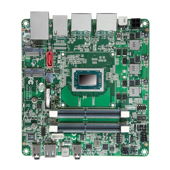
1-2 Mainboard Layout The following figure shows the location of components on the mainboard. See page 5 for component description. Note: Picture is for reference only, actual board may be slightly different. See next page for details. ~ 4 ~... - Page 10 Item Component description Item Component description AMD FP5 APU SATA Power Header, 2.50mm pitch DDR4 SO-DIMM *2 GPIO Header, 2.00mm pitch M.2 E-Key slot for Wifi/BT card Front Panel Header, 2.00mm pitch M.2 M-key for SSD device COM Header, 2.00mm pitch 4-pin 12V ~ 19V ATX Power CPU Fan Header, 2.54mm pitch Connector...
-
Page 11: Mainboard Dimension
1-3 Mainboard Dimension PCB size: 147.3 x 139.7mm ~ 6 ~... - Page 12 Cooler size: 96.9 x 78.55 x 34.85mm 96.9mm 78.55m CPU Fan Header 34.85mm 3.55mm ~ 7 ~...
-
Page 13: Chapter 2 Installation
Chapter 2 Installation 2-1 Installing System Memory This mainboard has two 260-pin SO-DIMM sockets for DDR4 memory. Supports 4GB, 8GB and 16GB DDR4 SO-DIMMs up to maximum 32GB. Supports 1.2v DDR4-2133/2400/2666/2933/3200* DIMMs with dual channel architecture. * The memory speed will be depend on CPU specification. Make sure that you install memory modules of the same type and density in different channel DIMM slots for Dual-Channel mode. -
Page 14: Installing Expansion Cards
2-2 Installing Expansion Cards The mainboard provides one M.2 E-Key slot for Wifi/Bluetooth card and one M.2 M-key for SSD device supporting SATA and PCIe interface. M.2 M-key for M.2 SSD LED1: device When the M.2 SSD device is functional, this Green LED is blinking. -
Page 15: M-Key Slot
M.2 M-Key Slot To install the M.2 SSD device: 1. Remove screws and align the notch on the M.2 SSD device edge connector with the tab in the slot. 2. Plug the M.2 SSD device firmly into the slot at a 20-degree angle, and until it clicks into place. -
Page 16: Connecting Cables And Jumper Settings
2-3 Connecting Cables and Jumper Settings This section takes you through all the necessary connections on the mainboard. 4-pin 12V~19V ATX Power Connector PW1, This power connector is used to provide power to the system. Align the power plug to the connector and press firmly until seated. Definition 12V~19V 12V~19V... -
Page 17: Front Panel Header
Front Panel Header The front panel header (CFP, 2.00mm pitch) on this motherboard is used to connect the front panel switches and LEDs. PWR_LED Attach the front panel power LED cable to these two pins of the connector. The Power LED indicates the system’s status. System Status Power LED indicates The LED is on... -
Page 18: Com Header
COM Header The Serial port header (COM1, 2.00mm pitch) can provide one serial port via an optional COM port cable. Definition Note: The pin definition of header and standard DB9 male pin out is different. Empty GPIO Header There is a GPIO (General-purpose input/output) header (2.00mm pitch) on the motherboard. -
Page 19: Smbus Header
SMBus Header This is a SMBus interface header (2.54mm pitch). Definition +3.3V Standby SMBus CLOCK SMBUS DATA Fan Headers There are two headers (CPUFAN and SYSFAN, 2.54mm pitch) on the motherboard. These fans can be speed detected/controlled and displayed in the Hardware Health Configuration section of the CMOS Setup. -
Page 20: Slew Speed Select Jumper
Slew Speed Select Jumper Adjustable Slew Rate for Minimize EMI Error. A slew rate control pin configures driver outputs for either high data rate or slew-controlled data rates. Slew-controlled outputs minimize the problems that caused by the reflections and ringing on long or un-terminated cables. Logical Low input will limit driver slew from either RS-232 to 1Mbps or RS-485 to 10Mbps. -
Page 21: Led Status Indicators
2-4 LED Status Indicators This mainboard provides three LEDs to indicate the system’s status. STANDBY LED (LED4, Blue): When the System is in Standby Mode, this LED is on. This LED will remain on as long as the motherboard is receiving constant power. -
Page 22: Chapter 3 Configuring The Bios
Chapter 3 Configuring the BIOS This chapter provides information on the BIOS Setup program and allows you to configure the system for optimum use. 3-1 Select Boot Device Select Boot Device Menu allows you to set the first boot device without entering BIOS Setup. -
Page 23: Control Keys
Users are welcome to download the latest BIOS version from our official website. Control Keys Please check the following table for the function description of each Control key. Control Key(s) Function Description / Moves cursor left or right to select screens ... -
Page 24: Main Menu
3-3 Main Menu When entering the Aptio Setup Utility, the main menu screen appears. This main menu includes the system overview and displays the basic system configuration, such as BIOS information, memory size and system date/time. Aptio Setup Utility - Copyright (C) 2018 American Megatrends, Inc. Setup Main Advanced... -
Page 25: Advanced Menu
3-4 Advanced Menu The Advanced menu items allow you to change the settings for the CPU, USB and other system devices. Press <Enter> to display the configuration options. Aptio Setup Utility - Copyright (C) 2018 American Megatrends, Inc. Setup Main Chipset Security Boot... -
Page 26: Dram Timing Configuration
Zen Common Options Core Performance Boost Allows you set the Core Performance Boost. Options: Disabled, Auto. Global C-state Control Allows you to control the IO based C-state generation and DF C-states. Options: Disabled, Enabled, Auto. UMC Common Options DDR4 Common Options DRAM Timing Configuration Aptio Setup Utility - Copyright (C) 2018 American Megatrends, Inc. - Page 27 Memory Clock Speed Recommend to select and follow below items option only. 1066MHz 2133MHz 1200MHz 2400MHz 1333MHz 2666MHz 1467MHz 2933MHz 1600MHz 3200MHz Note: Please attention DRAM timing configuration " WARNING" description. If there is no boot after setting, please to do CMOS clear.
- Page 28 UMA Version Allows you to select the UMA version. Options: Legacy, Non-Legacy, Hybrid Secure, Auto. UMA Frame buffer Size This item will only appear when “Integrated Graphics Controller” item is set to “Forces” option and “UMA Mode” item is set to “UMA_SPECIFIED” option. It controls the amount of system memory that is allocated to the integrated graphics processor.
-
Page 29: Amd Pbs
Options: Disabled, Enabled, Auto. AC Power Loss Options Ac Loss Control Enables your computer to automatically restart or return to its last operating status after power returns from a power failure. Options: Always Off, Always On, Previous. AMD PBS Aptio Setup Utility - Copyright (C) 2018 American Megatrends, Inc. Setup Advanced AMD Firmware Version... -
Page 30: Realtek Pcie Gbe Family Controller (Mac:dc:9C:52:08:12:68)
AMD Firmware Version Show all of AMD Firmware Version. Aptio Setup Utility - Copyright (C) 2018 American Megatrends, Inc. Setup Advanced AMD Firmware Version AGESA Version PavenPI-FP5-AM4 1.1.0.5 PSP BootLoader Version 0.8.0.42 PSP SecureOS Version 0.8.0.42 ABL Version 18041720 APCB Version 0029 AP0B Version 0011... -
Page 31: Realtek Pcie Gbe Family Controller (Mac:dc:9C:52:08:12:69)
Realtek PCIe GBE Family Controller (MAC:DC:9C:52:08:12:69) Aptio Setup Utility - Copyright (C) 2018 American Megatrends, Inc. Setup Advanced Driver Information Driver Name: Realtek UEFI UNDI Driver Driver(Beta) Driver Version: 2.020B1 Driver Released Date: 2013/01/18 : Select Screen Device Information Select Item Device Name: Realtek PCIe GBE Family Controller... -
Page 32: Amd Ftpm Configuration
AMD fTPM Configuration Aptio Setup Utility - Copyright (C) 2018 American Megatrends, Inc. Setup Advanced AMD fTPM switch [AMD CPU fTPM] To select. 0:Auto(Depend on Tcg modudle). 1:Disabled fTPM. 2:OnBoard SPI TPM2.0 : Select Screen Select Item Enter: Select +/-: Change Opt. - Page 33 Enable ACPI Auto Configuration This item allows you to enable ACPI Auto Configuration. Options: Enabled, Disabled. Enable Hibernation This item allows you to enable system ability to Hibernate (OS/S4 Sleep Sate). This option may be not effective with some OS. Options: Enabled, Disabled.
-
Page 34: Sata Configuration
SATA Configuration Aptio Setup Utility - Copyright (C) 2018 American Megatrends, Inc. Setup Advanced SATA Configuration SATA Port0 PLEXTOR PX-128 (128.0GB) SATA Port1 (S1) Not Present : Select Screen Select Item Enter: Select +/-: Change Opt. General Help Previous Values F3/F9: Optimized Defaults F4/F10:Save and Exit ESC:... -
Page 35: Hardware Monitor
Change Settings Select an optimal setting for super I/O device. Options: Auto, IO=3F8H; IRQ=4; IO=3F8h; IRQ=3,4,5,6,7,9,10,11,12; IO=2F8h; IRQ=3,4,5,6,7,9,10,11,12; IO=3E8h; IRQ=3,4,5,6,7,9,10,11,12; IO=2E8h; IRQ=3,4,5,6,7,9,10,11,12. Hardware Monitor Aptio Setup Utility - Copyright (C) 2018 American Megatrends, Inc. Setup Advanced PC Health Status CPU Fan Stopped Working Prompt [Enabled] SmartFan Configuration APU Temperature... -
Page 36: Smart Fan Configuration
APU / System Temperature Displays the current CPU / System Temperature. CPUFAN / SYSFAN Speed Displays the current CPU Fan / System Fan Speeds. APU Vcore / APU NB / VCC3V The current voltages are automatically detected and displayed by the system. Smart Fan Configuration Aptio Setup Utility - Copyright (C) 2016 American Megatrends, Inc. -
Page 37: Rtc Wake Settings
RTC Wake Settings Aptio Setup Utility - Copyright (C) 2018 American Megatrends, Inc. Setup Advanced Enable or disable System wake Wake system at specific Time [Disabled] on alarm event. When enabled, System will wake on the Wake System duration after [Disabled] hr::min specified. -
Page 38: Cpu Configuration
CPU Configuration Aptio Setup Utility - Copyright (C) 2018 American Megatrends, Inc. Setup Advanced CPU Configuration Enable/disable the Cool ‘n’ Quiet. Module Version: RavenCpu 18 AGESA Version: RavenPI 1105 AMD Cool’n’ Quiet [Enabled] PPC Adjustment [PState 0] : Select Screen ... -
Page 39: Network Stack Configuration
CPU Information Displays current processor information. Aptio Setup Utility - Copyright (C) 2018 American Megatrends, Inc. Setup Advanced Socket0: AMD Ryzen Embedded V1807B with Radeon Vega Gfx 4 Core(s) Running @ 3412 MHz 1350 mV Processor Family: 17h Processor Model: 10h-1Fh CPUID: 00810F10 Max Speed:3350 MHZ Min Speed:1600 MHZ... - Page 40 Ipv4 PXE Support This item is used to enable or disable the Ipv4 PXE boot support. If disabled, Ipv4 PXE boot option will not be available. Options: Enabled, Disabled. Ipv4 HTTP Support This item is used to enable or disable the Ipv4 HTTP boot support. If disabled, Ipv4 HTTP boot option will not be available.
-
Page 41: Csm Configuration
CSM Configuration Aptio Setup Utility - Copyright (C) 2018 American Megatrends, Inc. Setup Advanced Enable/Disable CSM Support Compatibility Support Module Configuration CSM Support [Enabled] CSM16 Module Version 07.79 GateA20 Active [Upon Request] Option ROM Messages [Keep Current] : Select Screen ... -
Page 42: Mvme Configuration
Option ROM execution This field controls the execution policy for devices other than Network, Storage or Video. Options: Do not launch, Legacy, UEFI. MVMe Configuration Aptio Setup Utility - Copyright (C) 2018 American Megatrends, Inc. Setup Advanced NVMe controller and Drive information Bus: 1 Dev:0 Func:0 KINGSTON SKC1000240g Nvme Size... -
Page 43: Usb Configuration
USB Configuration Aptio Setup Utility - Copyright (C) 2018 American Megatrends, Inc. Setup Advanced USB Configuration Enables Legacy USB support; USB Module Version AUTO option disables legacy support if no USB devices are USB controllers: connected, DISABLED option 2 XHCIs will keep USB devices available USB Devices: only for EFI applications. - Page 44 Device reset time-out Sets USB mass storage devices start unit command time-out. Options: 10 sec, 20 sec, 30 sec, 40 sec. Device power-up delay Maximum time the device will take before it properly reports itself to the Host controller. ‘Auto’ uses default values; for a Root port it is 100ms, for a Hub port the delay is taken from Hub descriptor.
-
Page 45: Chipset Menu
3-5 Chipset Menu The chipset menu items allow you to change the advanced chipset settings. Press <Enter> to display the sub-menu. Aptio Setup Utility - Copyright (C) 2018 American Megatrends, Inc. Setup Main Advanced Security Boot Save & Exit Chipset South Bridge Parameters South Bridge North Bridge... -
Page 46: North Bridge
USB Port (CN7 USB3.1 Type C) / USB Port (CN7 USB3.1 Type C - Reverse) Allows you to enable or disable USB port. Options: Enabled, Disabled. North Bridge Aptio Setup Utility - Copyright (C) 2018 American Megatrends, Inc. Setup Chipset North Bridge Configuration View Information related to DIMM... -
Page 47: Security Menu
3-6 Security Menu The Security menu allows you to change the system security settings. Aptio Setup Utility - Copyright (C) 2018 American Megatrends, Inc. Setup Main Advanced Chipset Boot Save & Exit Security Password Description Set Administrator Password. If ONLY the Administrator’s password is set, then this only limits access to Setup and is only asked for when entering Setup. -
Page 48: Boot Menu
3-7 Boot Menu The Boot menu is used to configure the boot settings and the boot priority. Aptio Setup Utility - Copyright (C) 2018 American Megatrends, Inc. Setup Main Advanced Chipset Security Save & Exit Boot Boot Configuration Number of seconds to wait for Setup Prompt Timeout setup activation key. -
Page 49: Save & Exit Menu
3-8 Save & Exit Menu The Save & Exit menu allows you to load the optimal default values for BIOS, and save or discard your changes to the BIOS items. Aptio Setup Utility - Copyright (C) 2018 American Megatrends, Inc. Setup Main Advanced... -
Page 50: Chapter 4 Driver Installation
Chapter 4 Driver Installation After the operating system has been installed, you need to install drivers for this mainboard. The support DVD that came with the motherboard contains necessary drivers and useful utilities that enhance the motherboard features. 4-1 Driver Install Insert the bundled driver DVD into your optical drive and the main menu will be displayed on your PC screen.
Need help?
Do you have a question about the FS-FP5V and is the answer not in the manual?
Questions and answers