
Subscribe to Our Youtube Channel
Related Manuals for Bolin Technology KBD-1010-R

Summary of Contents for Bolin Technology KBD-1010-R
- Page 1 KBD-1010 Universal PTZ Camera Remote Controller USER MANUAL VERSION: KBD-M-03252020 KBD-1010-R | KBD-1010-RNV © 2020 Bolin Technology...
-
Page 2: Table Of Contents
Contents IMPORTANT INFORMATION ..............................4 WHAT’S IN THE BOX ................................6 OVERVIEW .................................... 7 : ....................................7 EATURES ..................................8 EYBOARD IAGRAMS KBD-1010 ...................................... 8 ......................................9 EYBOARD LED S ..................................10 CREEN ISPLAY ....................................11 UNCTION ..................................12 YSTEM VERVIEW (PTZ C ) ........................ - Page 3 Scanning local network for available VISCA over IP cameras ....................43 Adding VISCA over IP cameras to be controlled via WAN ...................... 43 INTERACTING WITH CAMERAS ............................. 44 RS422 A/B ................................44 BUTTON ................................45 PTIONS FOR CALLING CAMERA .................................. 45 ONTROLLING A AMERA Engaging the Camera OSD Menu for non-IP cameras ......................
-
Page 4: Important Information
Before operating the unit, please read this manual thoroughly and retain it for future reference. Copyright Copyright 2018 Bolin Technology all rights reserved. No part of this manual may be copied, reproduced, translated, or distributed in any form or by any means without prior consent in writing from our company. - Page 5 Maintenance Precautions: • Ensure that no moisture or liquid comes into contact with any surface of the keyboard, as liquid may damage the functions of the keyboard. • Keep dust the RJ-45 ports free from dust and moisture • Only use the original, uncut (not spliced) power supply that is included with the keyboard Regulatory Compliance FCC Part 15 This equipment has been tested and found to comply with the limits for digital device, pursuant to part 15 of the FCC...
-
Page 6: What's In The Box
WHAT’S IN THE BOX When the “Optional” Accessories will be needed: • When RS422, RS485 and RS232 cameras are being controlled simultaneously • When more than one group of RS422/RS485 cameras is being controlled simultaneously • When a 8 Pin Mini Din RS232 connector camera needs to be connected to and controlled. -
Page 7: Overview
Overview This user guide is suitable for the following models: • KBD-1010-R (Regular controller with RS232 RS422 with no IP feature) • KBD-1010-RN (IP camera controller with serial port and ONVIF IP protocol) • KBD-1010-RNV (IP camera controller with serial port and ONVIF IP and VISCA Over IP protocol) Key Features: •... -
Page 8: Keyboard Diagrams
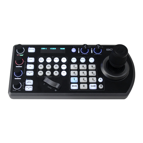
Keyboard Diagrams KBD-1010 1. Power Button Power on / Power off the keyboard 2. 12V DC Power Port, wide range input tolerance from 5V-48VDC Connect the supplied DC power adaptor and cord 3. Firmware Interface Button Engages firmware update mode on the keyboard 4. -
Page 9: Keyboard
Keyboard 1. White Balance, (Auto, Manual): Press once for Auto, press again to activate manual adjustments 2. Lock – locks all image adjustment buttons and dials 3. Exposure ( Full Auto, Iris Priority, Shutter Priority, Manual Iris Gain, Manual Shutter Gain, Black Level. 4. -
Page 10: Led Screen Display
LED Screen Display 1. Camera Title, displays the title is set for the camera being controlled. 2. Camera Identifier – Camera ID, identifies which camera is being controlled, and the protocol being used 3. Protocol, the control protocol that the camera being controlled is using. 4. -
Page 11: Junction Box
Junction Box 1. RJ45 port for connection between Junction Box and The Keyboard Controller 2. 12V DC Power Port Connect the supplied DC power adaptor and cord 3. Junction Box body 4. Terminal Contact connection for RS422 or RS232 5. RJ45 port for connection between Junction Box and The camera Use Network cable to connect directly 6. -
Page 12: System Overview
System Overview Cross-Protocol Mix Control (PTZ Controller Mode) Figure 1 - When the junction box is powered, it will provide power to the keyboard via any port that it is connected to --RS232, IP, RS422(A), RS422(B). No additional power supply is required for the keyboard a powered junction box is being used. Please Note, regarding Serial Control protocols (RS422/RS485 and RS232): •... -
Page 13: Connection
Connection The controller supports serial RS232/RS422 and IP Cross protocol mix-control. It allows you to use RS232/RS422/IP control on one controller to control cameras (Protocol support: VISCA, PELCO D/P, ONVIF, VISCA over IP, CGI*) in a single system. Power directly connect to the keyboard:... -
Page 14: Connector Pinout Definition
Figure 2 - Power supply is required at EITHER the keyboard OR the Junction Box. If the junction box is powered, no additional power supply is needed for the keyboard, as the junction box will provide power to the keyboard via the control port Connector Pinout Definition... -
Page 15: Ip Connection
IP connection For more information regarding adding ONVIF and VISCA over IP cameras to be controlled by the keyboard, please see the section on Keyboard IP Configuration Make Serial Port Connection The controller supports serial RS232/RS422 and IP Cross protocol mix-control. It allows you to use RS232/RS422/IP control on one controller to control cameras (Protocol support: VISCA, PELCO D/P, ONVIF, VISCA over IP) in a single system. -
Page 16: Rs232 Connection
RS232 connection -Use for the controller with Non-Bolin camera connection. Bolin camera connection see the separate section following. Follow the diagram below for the following options:... -
Page 18: Rs422 Connection
RS422 connection -Use for the controller with Non-Bolin camera connection. Bolin camera connection see the separate section following. • • • • Follow the diagram below for the following options:... -
Page 22: Rs485 Connection
RS485 connection -Use for the controller with Non-Bolin camera connection. Bolin camera connection see the separate section following. Follow the diagram below for the following options: • •... -
Page 26: Ip Control
IP Control Use ONVIF IP Control: Use VISCA OVER IP Control:... -
Page 27: Cross-Protocol Mix Control
Cross-Protocol Mix Control Tally Light GPI I/O connection GPI connection with RS422 VISCA control connection Cable Preparation 1. Build standard multiple cameras RS-422 daisy chain control connection between the keyboard controller and the cameras. (For more RS422 control information details please refer to Keyboard Controller user guide) a. - Page 28 b. Via RJ45 RS422/232 adaptor 2. Built Tally/Contact Function cable connection between the Keyboard Controller and Video Switcher(Sony) Set UP 1. GPI I/O Input mode - Tally signal is sent by Video Switch a. Connect camera with keyboard by standard RS-422 control cable; b.
- Page 29 e. If switch to camera 2 on video switch, then camera 2 tally light will on and camera 1 tally light will off; 2. GPI I/O Output mode -Tally signal is sent by Keyboard Controller a. Connect camera with keyboard by standard RS-422 control cable; b.
-
Page 30: How To Make The Connection With Bolin Products
GPI connection with VISCA OVER IP control connection How to make the connection with BOLIN products Please see the User Guide “BOLIN Camera and Keyboard Controller Connection” that you can download it at www.bolintechnology.com product pages. Control Mode - Video Router Switch Cross-Protocol Mix Control (Video Router Switch Mode) - Page 31 Figure 3 - When the junction box is powered, it will provide power to the keyboard via any port that it is connected to --RS232, IP, RS422(B). No additional power supply is required for the keyboard a powered junction box is being used. In Video Router Switch control mode, it allows you to use keyboard CAM key and MON key to select any one of the cameras displaying on any one of the monitors within the video router/matrix system with PTZ camera control.
-
Page 32: Configuration File Export & Import
Go to Keyboard Setting to select Video Router Mode in Control COM: 3 PELCO 9600 OK Mode. MON: 2 STUDIO B01 Connect to the keyboard RS422(A) port to a video router/matrix that supports RS422 control, such as Blackmagic Smart VideoHub. L/R: OFF U/D: OFF This keyboard integrated Blackmagic Matrix Switching... - Page 33 NOTE: • The Export & Import function is only available while the keyboard is under home screen. Import : (Camera Setting Data) 1. Setup IP configuration to the new keyboard and login the web interface. 2. Access to Import Camera Setting Data or Import Keyboard Setting Data page 3.
-
Page 34: Keyboard Configuration
Keyboard Configuration Interacting with the KBD-1010 Setup: P/T Speed Dial: • Rotate: Move Cursor • Click: Select • Long Press: Invert L/R (pan axis) • Zoom Speed Dial: • Rotate: Select Value • Click: Save • Long Press: Invert U/D (Tilt axis) Setup button Default Password: 0000 The password can be changed under... -
Page 35: Button Light
• If setting the IP address to a STATIC address, ensure that the Type field shows STATIC, and then rotate the P/T Speed dial to move the cursor between Keyboard Setting Menu IP Configuration Menu the IP address octets. Move the cursor to each octet and use the alphanumeric >IP CONFIGURATION >Type: STATIC... -
Page 36: Factory Default
P/T Reset – Reset the selected camera Power – Power off the selected camera Mute – Mute the audio from the selected camera Picture Freeze – Freeze the image of the selected camera Picture Flip – Flip the image of the selected camera Picture LR Reverse –... -
Page 37: Password Setting
buttons which are not selected will light in red. You can select a camera by pressing its respective CAMERA button (lit in red). ▪ The tally lamp of the camera receiving a command from the TALLY/CONTACT connector lights. * ▪ On Air - Displays the tally input lamp corresponding to the number of the camera with tally input ON. -
Page 38: Joystick Zoom Setting
Joystick Zoom Setting Keyboard Setting Menu The joystick ring can control the camera’s zoom. This can be toggled under Setup/ IP CONFIGURATION Joystick Zoom. BUTTON LIGHT This setting can be changed by rotating the Zoom Speed knob while the setting is ASSIGNED KEY: F1 selected FACTORY DEFAULT... -
Page 39: Control Mode
• USER, you can set the port that your camera is using. • Please consult your camera provider for port information. This keyboard supports any brand of Visca Over IP cameras in a same system. If you have Visca-Over-IP cameras from more than one different camera makers, you may have to set the camera port differently. -
Page 40: Adding An Onvif Camera To Keyboard
Adding an ONVIF camera to Keyboard Adding manually from Local Area Network (LAN) Selecting ONVIF as the protocol and clicking the P/T Speed dial will cause the ONVIF Camera Setup menu to appear • Must know about the IP address of the camera. -
Page 41: Adding Onvif Cameras To Be Controlled Via Wan
ONVIF Camera Setup Menu >IP Address: >192. 168. 0. 100 >User Name >- >Password: >- >Port: 80 >Exit Repeat this process for each discovered camera that you wish to add to the KBD-1010 Adding ONVIF cameras to be controlled via WAN 1. -
Page 42: Adding Avisca Over Ip Camera To Keyboard
Adding a VISCA over IP camera to Keyboard Adding manually from Local Area Network (LAN) Selecting VISCAIP (VISCA over IP) as the protocol and clicking the P/T Speed dial will cause the VISCAIP configuration menu to appear • Rotate the P/T Speed dial to move Camera Setting Menu VISCAIP Configuration Menu the cursor between the IP address... -
Page 43: Scanning Local Network For Available Visca Over Ip Cameras
Scanning local network for available VISCA over IP cameras • Press the Search button to bring up the Auto Search menu • Move the cursor to VISCA-IP • Select Yes to start the search • A list of discovered cameras will appear showing the cameras that have been discovered. Scroll through the discovered cameras using the Zoom Speed dial •... -
Page 44: Interacting With Cameras
Protocol: Both (TCP and UDP) • Within the Setup menu of the KBD-1010, add the VISCA over IP camera using the WAN IP of the camera location as the IP Address • Click the P/T Speed dial to save Interacting with Cameras Dual RS422 button A/B... -
Page 45: Options For Calling Camera
Options for calling camera 1. Use the keypad to call the camera by CAM ID a. Enter the CAM ID on the keypad b. Press CAM 2. Call the IP cameras by selecting from a list of available devices a. Press the Inquiry button b. -
Page 46: Setting And Calling Presets
Setting and calling presets Setting / creating presets: 1. Move the camera to the desired position 2. Enter the desired preset number on the alphanumeric keyboard, and then hold the Preset button for 3 seconds to save Calling presets: 1. Enter the desired preset number on the alphanumeric keypad 2. -
Page 47: Adjusting Image Parameters
Adjusting image parameters The following image parameters can be set/adjusted by using the Image Adjustment Panel... -
Page 48: Firmware Upgrade
Firmware Upgrade Please upgrade IP firmware first, if you want to upgrade both IP firmware and MCU firmware, Keyboard IP firmware upgrade. Connect PC to the keyboard via LAN 1. Find IP address of the keyboard in the menu Model Information. 2. -
Page 49: Lcd Screen Setting Tree
LCD Screen Setting Tree CAMERA SETTING SETUP Button CAMXXX 001-255 TITLE User entry using keypad Baud Rate 2400, 9600, 19200, 38400 VISCA Port RS422 / RS232 PELCO-D Baud Rate 2400, 9600, 19200, 38400 PELCO-P Baud Rate 2400, 9600, 19200, 38400 IP Address User entry using keypad User Name... -
Page 50: Dimensions
Dimensions Unit: mm KBD-1010 Junction Box... - Page 51 2082 TECHNOLOGY LLC BOLIN TECHNOLOGY...
Need help?
Do you have a question about the KBD-1010-R and is the answer not in the manual?
Questions and answers