
Related Manuals for Synrad f201


Summary of Contents for Synrad f201
- Page 1 Operator’s Manual ® 4600 Campus Place Mukilteo, WA 98275 1.800.SYNRAD1 1.425.349.3500 1.425.349.3667 e-mail synrad@synrad.com www.synrad.com...
- Page 2 Operator’s Manual Version 3.2 SYNRAD is a registered trademark of Novanta Corporation. Novanta Corporation 2019. All © © Rights Reserved. No reproduction without written authorization. DATE: March 2019...
-
Page 3: Table Of Contents
Firestar nomenclature Unpacking Getting Started Introduction Firestar nomenclature Unpacking Incoming inspection Packaging guidelines Removing the lifting handles Inventory f201 lasers Connecting Cooling connections PS-96 power supply connections PS-96 AC input section Control connections Other connections SYNRAD f201 Operator’s Manual Version 3.2... - Page 4 Cooling connections PS-96 power supply connections Other connections Controls and indicators f201 lasers Initial start-up With a UC-2000 Controller Initial start-up Without a UC-2000 Controller Initial start-up Technical overview Laser tube Optical resonator Technical overview SYNRAD f201 Operator’s Manual Version 3.2...
- Page 5 Disabling f201 lasers Daily inspections Storage/shipping Cleaning optical components Troubleshooting Introduction Troubleshooting Operational flowchart Troubleshooting Functional block diagram Troubleshooting Status LEDs Troubleshooting Laser fault indications Resetting faults Troubleshooting Other laser faults Troubleshooting Beam delivery optics Troubleshooting SYNRAD f201 Operator’s Manual Version 3.2...
- Page 6 Table 2-4 Three-phase AC electrical recommendations. Table 2-5 Single-phase AC electrical recommendations. Table 2-6 Purge gas specifications. Figure 3-1 F201 controls and indicators (front). Figure 3-2 F201 controls and indicators (rear). Figure 4-1 beam characteristics. Figure 4-2 “Flying optics” beam path.
- Page 7 Figure 4-15 Firestar output driving relay. Figure 4-16 Firestar output driving PLC input module. Figure 4-17 Wiring Set 1 and Set 2 to power external circuits. Table 4-7 f201/f400 DC Power connector pinouts. Table 4-10 Firestar f201 general specifications. Table 5-1 Required cleaning materials.
-
Page 8: Synrad F201 Operator's Manual Version
Trademark & Copyright information SYNRAD and Firestar™ are registered trademarks of SYNRAD © © All other trademarks or registered trademarks are the property of their respective owners. © 2019 by SYNRAD. All rights reserved. SYNRAD f201 Operator’s Manual Version 3.2... - Page 9 Return Authorization (RA) number is required; this number must be clearly marked on the outside of the shipping container in order for the unit to be properly processed. If replacement parts are sent to you, then you are required to send the failed parts back to SYNRAD for evaluation unless otherwise instructed.
- Page 10 Regional Sales Managers also serve as the liaison between you and our Applications Lab in processing material samples per your specifications. To speak to the Regional Sales Manager in your area, call SYNRAD at 1.800. SYNRAD1.
- Page 11 EU headquarters For assistance in Europe, contact SYNRAD European subsidiary, SYNRAD Europe, at: ® Novanta Distribution (USD) GmbH © Parkring 57-59 85748 Garching bei München, Germany Phone: +49 89 31707-0 Web: www.synrad.com E-mail: EMEA-service@novanta.com SYNRAD f201 Operator’s Manual Version 3.2...
-
Page 12: Laser Safety
General & Other Hazards – provides important information about the hazards and unsafe practices that could result in death, severe injury, or product damage. Disposal – information on your f201 laser parts and/or components as they pertain to disposal. Additional Safety Information – describes how to find additional information about your f201 laser. -
Page 13: Figure 1-1 Labeling Terms And Definitions
For laser systems being used or sold outside the U.S.A., cus- tomers should refer to and follow the laser safety precautions described in European Normative and International Elec- trotechnical Commission documents IEC/TR 60825-14:2014, Safety of Laser Products – §14: A User’s Guide. SYNRAD f201 Operator’s Manual Version 3.2... -
Page 14: General Hazards
Do not use air dusters containing difluoroethane in any area adjacent to CO laser systems because difluo- roethane persists for long time periods over wide areas. SYNRAD f201 Operator’s Manual Version 3.2... - Page 15 Laser Safety General hazards F201 lasers should be installed and operated in manufacturing or laboratory facilities by trained personnel only. Due to the considerable risks and hazards associated with the instal- lation and operational use of any equipment incorporating a laser, the operator must follow product warning labels and instructions to the user regarding laser safety.
-
Page 16: Other Hazards
This product contains components that are considered hazardous industrial waste. If a sit- uation occurs where the laser is rendered non-functional and cannot be repaired, it may be re- turned to SYNRAD who, for a fee, will ensure adequate disassembly, recycling and/or disposal of the product. - Page 17 Specified by 21 CFR 1040.10 or IEC 60825-1 laser "low" periods. This is automatically provided WATER DAMAGE CAN with Synrad's UC Series power controller. This signal OCCUR IF COOLING WATER keeps the plasma ionized during laser "low" periods 4600 Campus Place, Mukilteo WA 98275 | 425.349.3500 and facilitates breakdown and pulse to pulse fidelity.
- Page 18 "Tickle" signal during standby or laser "low" periods. This is automatically provided WATER DAMAGE CAN with Synrad's UC Series power controller. This signal 4600 Campus Place, Mukilteo WA 98275 | 425.349.3500 OCCUR IF COOLING WATER keeps the plasma ionized during laser "low" periods and facilitates breakdown and pulse to pulse fidelity.
-
Page 19: Figure 1-5 F 201 Hazard Label Locations
These RF Excited Lasers must be provided with a pre-ionizing "Tickle" signal during standby or laser "low" periods. This is automatically provided with Synrad's UC Series power controller. This signal keeps the plasma ionized during laser "low" periods and facilitates breakdown and pulse to pulse fidelity. -
Page 20: Agency Compliance
Incorporation of certain features is dependent on the laser version (Key- switch or OEM). Table 1, Class 4 safety features, indicates which features are available on f201 lasers, the type and description of the feature, and if the feature is required by CDRH regula- tions. -
Page 21: Federal Communications Commission (Fcc)
The FCC regulations that govern industrial, scientific, and medical (ISM) equipment are fully described in 47 CFR, §18, §§C. SYNRAD f201 lasers have been tested and found to comply by demonstrating performance characteristics that have met or exceeded the requirements of 47 CFR, §18, §§C for Radiated and Conducted Emissions. -
Page 22: European Union (Eu) Requirements
Table 1, Class 4 safety features, summarizes f201 product features, indi- cating the type and description of features and whether those features are required by European Union regulations. - Page 23 Warning Laser exterior labels Labels attached to various external housing locations to warn personnel of potential laser hazards. 1 Not available on f201 OEM lasers SYNRAD f201 Operator’s Manual Version 3.2...
- Page 24 Laser Safety When integrating SYNRAD f201 OEM lasers, the Buyer and/or integrator of the end system is responsible for meeting all applicable Standards to obtain the CE mark. To aid this compliance process, SYNRAD testing program has demonstrated that f201 lasers comply with the relevant requirements of 2014/30/EU, the Electromagnetic Compatibility Directive, as summarized in the table below.
- Page 25 Radiated Emissions, Group 1, Class A EN 61000‐6‐4:2007 Conducted Emissions, Group 1, Class A EN 61000‐6‐2:2005 Electrostatic Discharge Immunity EN 61000‐6‐2:2005 RF Electronic Fields Immunity EN 61000‐6‐2:2005 Electrical Fast Transient/Burst Immunity EN 61000‐6‐2:2005 Conducted RF Disturbances Immunity *OEM lasers do not comply with EN 60825‐1:2014, Safety of Laser Products. Buyers of OEM laser products are solely responsible for meeting applicable Directives and Standards for CE compliance and marking. Corporate Officer: European Contact: Novanta Distribution (USD) GmbH Parkring 57‐59 85748 Garching bei München, Germany Tim Freni, Quality Manager of SYNRAD 3/4/19 MADE IN THE U.S.A. Dated: 900‐20976‐19 Rev B Figure 1-6 F100 declaration of conformity. SYNRAD f201 Operator’s Manual Version 3.2...
-
Page 26: Figure 1-7 F201 Declaration Of Conformity
EN 61000‐6‐4:2007 Radiated Emissions, Group 1, Class A EN 61000‐6‐4:2007 Conducted Emissions, Group 1, Class A EN 61000‐6‐2:2005 Electrostatic Discharge Immunity EN 61000‐6‐2:2005 RF Electronic Fields Immunity EN 61000‐6‐2:2005 Electrical Fast Transient/Burst Immunity EN 61000‐6‐2:2005 Conducted RF Disturbances Immunity *OEM lasers do not comply with EN 60825‐1:2014, Safety of Laser Products. Buyers of OEM laser products are solely responsible for meeting applicable Directives and Standards for CE compliance and marking. Corporate Officer: European Contact: Novanta Distribution (USD) GmbH Parkring 57‐59 85748 Garching bei München, Germany Tim Freni, Quality Manager of SYNRAD Date: 3/4/19 MADE IN THE U.S.A. 900‐20976‐14 Rev B Figure 1-7 F201 declaration of conformity. SYNRAD f201 Operator’s Manual Version 3.2... -
Page 27: Introduction
Use information in this chapter to prepare your Firestar f201 laser for operation. The order of information presented in this chapter is the same as the order of tasks that you will need to perform. The best way to get your laser ready for operation is to start at Unpacking and work your way through Connecting. -
Page 28: Introduction
Keyswitch and OEM models available Firestar nomenclature Firestar f201 lasers are available only as OEM lasers; they do not include either a keyswitch or manual shutter assembly. SYNRAD’s OEM lasers are primarily designed as components for integration into larger processing systems by the Original Equipment Manufacturer (OEM) or System Integrator who bears the responsibility for meeting the appropriate laser safety requirements for Class 4 laser systems. -
Page 29: Unpacking
■ F201 lasers and power supplies are heavy and awkward to move. Use appropriate lifting techniques, additional personnel, and/or hoisting equipment to prevent a risk of injury when rigging this equip- ment. -
Page 30: Figure 2-1 Unpacking The Laser
Note: Do not lift or support the laser using the cooling fittings. Lift the laser using the lifting handles, mounting feet or baseplate only. After removing the laser, pull out all the accessory items packaged with the laser. SYNRAD f201 Operator’s Manual Version 3.2... -
Page 31: Figure 2-2 Removing Lifting Handles
Retain the three M10 × 1.5 capscrews. Use these bolts for mounting if metric fasteners are required. Store the lifting attachments so that they can be reinstalled if the laser is moved to another loca- tion. SYNRAD f201 Operator’s Manual Version 3.2... -
Page 32: Inventory
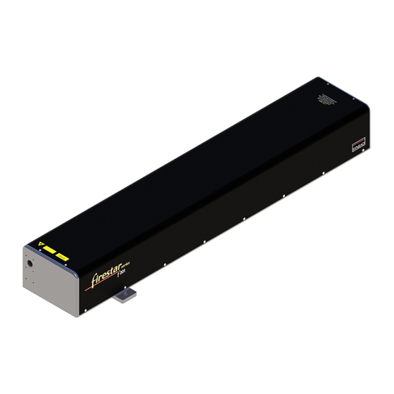
Inventory f201 lasers SYNRAD CO Welcome flier Quick Start Plug Chiller Fittings and Mounting Bolts Cooling Tubing DC Power Cable Firestar f-Series Laser (f100 shown) Figure 2-3 F201 shipping box contents. SYNRAD f201 Operator’s Manual Version 3.2... - Page 33 3/8" NPT female threads. Spherical Washer Sets (not shown) – used in conjunction with Firestar f201 mounting bolts to align the laser to your mounting surface. Shipped with f201 lasers only.
- Page 34 Fastening f201 lasers from above To fasten your f201 laser to a mounting surface from above, perform the following steps: Refer to the appropriate outline and mounting drawing for dimensions and then drill and tap three mounting holes into your mounting surface. For SAE installations, drill and tap three 5/16–18 (f201).
- Page 35 Figure 2-5 Detail of fastening into mounting surface. Fastening f201 lasers from below To fasten your f201 laser to a mounting surface from below, perform the following steps: Refer to the appropriate outline and mounting drawing for dimensions and then drill three 8.5 mm (f201) holes into your mounting surface.
-
Page 36: Connecting
WATER IN/WATER OUT fittings from 1/2-inch standard to 12-mm metric tubing. The ship kit sent with your f201 laser includes a cooling kit containing two each 1/2-inch male to 1/2-inch female 90° adaptors and two each 1/2-inch male to 12-mm female 90° adaptors. If required, many tubing and fitting manufacturers can supply 1/2-inch to 12-mm straight fittings. - Page 37 Avoid glycol-based additives because they reduce the coolant’s heat capacity and high concentrations may affect power stability. For SYNRAD lasers, the minimum coolant setpoint is 18 °C (64 °F) so glycol is not necessary unless the chiller is subjected to freezing temperatures. If tap water is used, chloride levels should not exceed a concentration of 25 parts per million (PPM) and total hardness should be below 100 PPM.
- Page 38 For example, if the air temperature is 85 °F (29 °C) and the relative humidity is 60%, then the dew point temperature is 70 °F (21 °C). Adjust the chiller’s temperature setpoint to 72 °F (22 °C) to prevent condensation from forming inside the laser. SYNRAD f201 Operator’s Manual Version 3.2...
- Page 39 Connecting f201 cooling tubing connections To connect cooling tubing to your f201 laser, refer to the figure below and perform the following steps. The numbered items that follow correspond to the step numbers in the following procedure. Remote...
-
Page 40: Ps-96 Power Supply Connections
Connecting PS-96 power supply connections The following procedures describe how to connect the PS-96 DC power supply to your f201 laser. When connecting other types of DC power sources, remember to follow proper Lockout/Tagout pro- cedures to ensure that AC power is de-energized, and then connect input AC power per the manufac- turer’s instructions. -
Page 41: Ps-96 Ac Input Section
Verify that input AC voltage to the DC power supply is physically locked out or disconnected. Locate the f201 DC Power cable. The DC Power cable is 5 meters (16 feet) long with a plug on one end and five (5) connection lugs on the other. This cable has a minimum bend radius of 87.4 mm (3.44"). - Page 42 Connect the third AC hot wire, typically blue, to the input terminal labeled “L3/N”. Single-phase input power requirements for SYNRAD PS-96 DC power supply are 208–264 VAC, 1Ø (single phase), 20 A maximum, 47–63 Hz. Table below provides recommendations for single-phase input wiring and fusing.
- Page 43 Connect the return (neutral) wire from circuit 1, typically white, to the input terminal labeled “L2/N”. Connect the hot wire from circuit 2, typically black, to the input terminal labeled “L2/L”. Connect the return (neutral) wire from circuit 2, typically white, to the input terminal labeled “L3/N”. SYNRAD f201 Operator’s Manual Version 3.2...
-
Page 44: Control Connections
Connecting Quick Start Plug In order for your f201 laser to properly operate, several input signals must be applied to the DB-15 User I/O connector before lasing is enabled. Voltage must be applied to Remote Interlock (Pin 3) and Shutter Open Request (Pin 10) inputs before the laser will fire. -
Page 45: Other Connections
(30–60 SCFH, Standard Cubic Feet per Hour) at a pressure not to exceed 34.5 kPa (5 PSI). The Gas Purge connector on your f201 laser must be connected to a source of nitrogen or clean, dry air only; do not use any other gases for purging. Purge gas specifications are listed in the table below. - Page 46 Do not use argon as a purge gas. Use only nitrogen or clean, dry air damage as described in Table 1-6, Purge gas specifications. SYNRAD f201 Operator’s Manual Version 3.2...
-
Page 47: Operation
Controls and indicators – displays and describes exterior controls and indicators on f201 lasers. ■ Initial start-up – explains how to start your f201 laser while verifying proper opera- tion. Danger This Class 4 laser product emits invisible infrared laser radiation in the 10.6 µm CO... -
Page 48: Figure 3-1 F201 Controls And Indicators (Front)
Refer to Firestar package outline drawings in the Technical Reference chapter for mounting dimensions. Note: When mounting optical components to f201 lasers, the 8–32 UNC fasteners must extend no further than 4.8 mm (0.19") into the laser’s faceplate. SYNRAD f201 Operator’s Manual Version 3.2... -
Page 49: Figure 3-2 F201 Controls And Indicators (Rear)
Refer to User I/O connections in the Technical Reference chapter for pinouts and signal descriptions. 12 Gas Purge Connector (f201 only) – provides a low pressure nitrogen (or pure air) purge gas con- nection to prevent dust and debris from entering the laser housing and damaging electronic or optical components. - Page 50 If the factory-wired Quick Start Plug is installed, the Remote Interlock indicator will illuminate green and the Shutter indicator will illuminate blue—if the manual Shutter Switch is Open. The Temp indi- cator will illuminate green if laser temperature is within safe operating limits. SYNRAD f201 Operator’s Manual Version 3.2...
- Page 51 Lase LED flickers. personal injury If your f201 laser fails to lase, refer to Troubleshooting in the Maintenance/Troubleshooting chapter for troubleshooting information. Without a UC-2000 Controller If you are not using a UC-2000 to control the laser, follow the procedure below to verify laser operation.
- Page 52 Do not use argon as a purge gas. Use only nitrogen or clean, dry air damage as described in the following table, Purge gas specifications. SYNRAD f201 Operator’s Manual Version 3.2...
- Page 53 This page intentionally left blank. SYNRAD f201 Operator’s Manual Version 3.2...
-
Page 54: Mounting
Use information in this chapter as a technical reference for your Firestar f201 laser. This chapter contains the following information: ■ Technical overview – briefly describes Firestar’s technology and basic optical setup. ■ Controlling laser power – explains various aspects of Firestar control signals. - Page 55 The optical resonator, in conjunction with the electrodes and the gas mixture, generates the laser beam. Firestar f201 optical resonators are comprised of three optical elements: a front mirror, a rear mirror, and an output window. These optical elements are fastened to the tube’s exterior and are exposed to its interior through holes in the end caps.
-
Page 56: Internal Rf Power Supply
Output Aperture Figure 4-1 beam characteristics. On f201 lasers, the beam waist is located one meter before the output aperture due to the addition of internal beam conditioning optics that improve beam quality and strip any side lobes present to pro- duce a Gaussian-like mode quality (M factor) of 1.2 ±0.1. -
Page 57: Optical Setup
Figure below shows how right angle turning mirrors in a “flying optics” setup help create this longer beam path. Firestar f201 lasers, with their internal one-meter beam path and conditioning optics, can be mounted right at the work area. - Page 58 > 99.997% purity; filtered to ISO Class 1 particulate level Nitrogen Cutting/Drilling High Purity Grade > 99.9500% purity; filtered to ISO Class 1 particulate level Oxygen Cutting/Drilling Ultra Pure Grade > 99.9998% purity; filtered to ISO Class 1 particulate level SYNRAD f201 Operator’s Manual Version 3.2...
-
Page 59: Controlling Laser Power
PWM input with a rise and fall time constant of ~150 µs; however, the laser cannot precisely follow PWM input signals if the “On” pulse is less than 150 µs in duration. At a constant 50% duty cycle, f201 lasers typically reach 90–100% of full optical output when operated at a frequency of 3 kHz. -
Page 60: Figure 4-3 Typical Firestar F201 Waveforms
Figure 4-3 Typical Firestar f201 waveforms. Firestar f201 lasers are designed to operate at Command signal base frequencies up to 100 kHz; how- ever, the choice of PWM frequency depends on the user’s specific application. In the majority of laser applications, the UC-2000’s default Command signal frequency of 5 kHz has proven to work well. -
Page 61: Operating Modes
(power). Analog voltage or current control Although Firestar f201 lasers cannot be controlled directly by analog voltage or current signals, this type of control is possible when using the UC-2000 Controller. The Controller is connected normally to the laser and analog voltage or current signals sent to the UC-2000’s ANV/C connector then control both... - Page 62 Note: SYNRAD lasers are designed for maximum performance using a 95% duty cycle. Increasing the maximum PWM percentage beyond 95% greatly increases the laser’s heat load with little or no corresponding increase in laser output power. Continuous operation at 99% duty cycle may lead to thermal instability and optical degradation.
- Page 63 While this situation can occur when using PWM Command signal frequencies of 5 kHz and less, it is im- portant to note that it isn’t the Command signal frequency itself that is the determining factor but rather this behavior happens only when the off time between PWM pulses exceeds 200 microseconds. SYNRAD f201 Operator’s Manual Version 3.2...
-
Page 64: User I/O Connections
■ Sample I/O circuits ■ I/O connections User I/O connection summary Table below provides a quick reference summary to Firestar f201 User I/O connections. Table 4-3 User I/O pin descriptions. Function Description PWM Return Use this input pin as the return side of the PWM Command signal. -
Page 65: Input/Output Signals
Signals in each category are fully described in the sections below. Following figure illus- trates the pin arrangement of the User I/O (15 pin female D-type subminiature) connector on Firestar’s rear panel. SYNRAD f201 Operator’s Manual Version 3.2... -
Page 66: Figure 4-5 User I/O Connector Pinouts
Power output can source up to 0.5 A and is protected by a 0.5 A self-resetting fuse. The return (ground) path must be through Pin 12, Auxiliary DC Power Ground. Pin 12 Auxiliary DC Power Ground SYNRAD f201 Operator’s Manual Version 3.2... -
Page 67: Figure 4-6 Auxiliary Power Supply Wiring
Remote Reset/Start Request signal is ignored when the Keyswitch is set to the OFF/RESET position. The manually-operated Keyswitch must be set to the ON position before the laser can be reset from a remote location. SYNRAD f201 Operator’s Manual Version 3.2... - Page 68 Reset/Start Request lines. Refer to the following table for input circuit specifications. Figure below illustrates how Remote Interlock inputs are factory-jumpered on the Quick Start Plug to enable lasing for initial testing and troubleshooting purposes. SYNRAD f201 Operator’s Manual Version 3.2...
-
Page 69: Figure 4-8 Input Equivalent Schematic
Pin 3 Remote Interlock Pin 8 Pin 1 Pin 4 +5 VDC Pin 11 Input Common PWM Input BNC Pin 12 Aux. DC Power Ground Pin 15 Pin 9 Figure 4-8 Input equivalent schematic. SYNRAD f201 Operator’s Manual Version 3.2... -
Page 70: Figure 4-7 Quick Start Plug Wiring Diagram
(Temp LED green). After an over temperature fault occurs, cool the laser and then cycle DC power to reset the laser. Refer to he following table for output circuit specifications. SYNRAD f201 Operator’s Manual Version 3.2... - Page 71 Following figure illustrates the output circuit’s equivalent internal schematic and the following provides Firestar f201 output circuit specifications. Table 4-5 Output circuit specifications. Output Device Specifications Bi-directional MOSFET 2.5 Ohms Rdson 10 MOhms Off Voltage ±24 VDC, max. Current 50 mA, max. SYNRAD f201 Operator’s Manual Version 3.2...
-
Page 72: Figure 4-10 Customer-Supplied Interlock
Firestar’s input circuit. USER I/O PINS Close switch to enable interlock –12 VDC (3) REMOTE INTERLOCK 0 VDC (11) INPUT COMMON Figure 4-11 Customer-supplied interlock, negative voltage. SYNRAD f201 Operator’s Manual Version 3.2... -
Page 73: Figure 4-12 Plc Driven Interlock Signal
PLC’s output module. OUTPUT USER I/O PINS MODULE (11) INPUT COMMON (+5–24V) (2) REMOTE RESET/START REQUEST (3) REMOTE INTERLOCK (10) SHUTTER OPEN REQUEST Figure 4-13 Multiple PLC driven inputs. SYNRAD f201 Operator’s Manual Version 3.2... -
Page 74: Figure 4-14 Firestar Output Driving Warning Lamp
Firestar outputs. USER I/O PINS (5) +24 VDC AUXILIARY POWER (6) LASER ACTIVE (12) AUX.DC POWER GROUND (13) OUTPUT COMMON Figure 4-15 Firestar output driving relay. SYNRAD f201 Operator’s Manual Version 3.2... -
Page 75: Figure 4-16 Firestar Output Driving Plc Input Module
PLC inputs. INPUT USER I/O PINS MODULE (13) OUTPUT COMMON (+5–24V) (6) LASER ACTIVE (7) OVER TEMPERATURE (8) LASER READY (14) SHUTTER OPEN (15) INTERLOCK OPEN Figure 4-16 Firestar output driving PLC input module. SYNRAD f201 Operator’s Manual Version 3.2... -
Page 76: Dc Power Cables
Depending on the additional length required, you may need to use larger gauge wire. f201 DC Power cables DC Power cables for f201 lasers are manufactured with #12 AWG wire; however, DC input current is split between two positive (+) and two negative (–) conductors. Firestar f201 DC Power cables are available in 5 meter (16.4 ft) and 7 m (23 ft) lengths. -
Page 77: Integrating Firestar Safety Features
Pin 2. Your control system can monitor the laser’s ready status on the User I/O connector by connecting your system’s input between Pin 8, Laser Ready, and Pin 13, Output Common (see Figure 4-16). SYNRAD f201 Operator’s Manual Version 3.2... -
Page 78: Integrating Firestar Safety Features
This output is closed when remote interlock circuitry is open (Remote Interlock LED illuminated red). The output is open (in a high-impedance state) and the Remote Interlock LED is green when interlock circuitry is closed. SYNRAD f201 Operator’s Manual Version 3.2... - Page 79 Figure 4-16 F201 packaging diagram. SYNRAD f201 Operator’s Manual Version 3.2...
-
Page 80: F201 General Specifications
Table 4-10 Firestar f201 general specifications. Parameter Firestar f201 Output Specifications Wavelength .............10.2–10.7 microns Power Output 1, 2 Continuous .............200 Watts Pulsed ..............250 Watts Power Stability ............± 7% Power Stability ............± 5% Mode Quality ............M = 1.2 ±0.1... - Page 81 Specifications subject to change without notice. 8 Firestar f201 lasers can be operated at coolant temperatures up to 28 °C (82 °F) in order to reduce problems associated with condensation; however, this may result in decreased laser performance and/or reduced laser lifetime.
- Page 82 This page intentionally left blank. SYNRAD f201 Operator’s Manual Version 3.2...
-
Page 83: Maintenance
Use information in this chapter to perform maintenance or troubleshoot your f201 laser. This chapter contains the following information: ■ Maintenance – describes typical f201 maintenance procedures. ■ Troubleshooting – explains how to troubleshoot common f201 problems. SYNRAD f201 Operator’s Manual Version 3.2... -
Page 84: Disabling F201 Lasers
Getting Started chapter for details on preventing condensation. When using compressed air as a purge gas on your f201 laser, empty water traps and oil separa- tors on each filter and/or dryer between the laser and your compressed air source. Compressed air purity must meet the purge gas specifications shown in Table 1-6 in the Getting Started chapter. -
Page 85: Storage/Shipping
When finished, cap all connectors to prevent debris from entering the cooling system. When shipping SYNRAD lasers to another facility, we highly recommend that you ship the unit in its original SYNRAD shipping container. If you no longer have the original shipping box and inserts, contact SYNRAD Customer Service about purchasing replacement packaging. -
Page 86: Table 5-1 Required Cleaning
Powder-free Air bulb Clean air bulb Ethyl or isopropyl alcohol Spectroscopic or reagent grade Acetone Spectroscopic or reagent grade Lens wipe (preferred) Optical (cleanroom) quality Cotton balls or cotton swabs High-quality surgical cotton/high-quality paper-bodied SYNRAD f201 Operator’s Manual Version 3.2... - Page 87 Carefully examine the optic under a good light. Certain contaminants or damage such as pitting cannot be removed. In these cases the optic must be replaced to prevent catastrophic failure. Repeat Steps 4 through 6 as required, removing all traces of contaminants and deposits. SYNRAD f201 Operator’s Manual Version 3.2...
-
Page 88: Introduction
Contact SYNRAD or a SYNRAD Authorized Distributor for repair or replace- ment information. To troubleshoot Firestar f201 lasers, it is necessary to understand the sequence of events that must happen before the laser can operate. Before attempting any service, we advise you to read the entire troubleshooting guide and review both the operational flowchart and the functional block diagram. -
Page 89: Operational Flowchart
OFF/RESET and then Ready indicator Ready indicator back to ON Yellow? Yellow? (on OEM lasers, cycle DC power) Apply PWM Command signal to laser Lase indicator illuminates Red to indicate laser output Figure 5-1 Operational flowchart. SYNRAD f201 Operator’s Manual Version 3.2... -
Page 90: Functional Block Diagram
Troubleshooting Functional block diagram Figure below is a functional block diagram illustrating the f201’s control architecture. Figure 5-2 f201 functional block diagram. SYNRAD f201 Operator’s Manual Version 3.2... -
Page 91: Status Leds
Troubleshooting Status LEDs Firestar f201 LED indicators, also mirrored as output signals on the User I/O connector, provide status in- formation to the user. Table below shows Firestar output signal and LED indicator states during normal and fault conditions. User I/O outputs are Closed when the state indicated by the signal name is True. -
Page 92: Table 5-3 Normal Operating
LED Indicator LED Status Output Signal Output Status Remote Interlock Interlock Open Closed Temp Green Over Temperature Open Ready Laser Ready Open Lase (tickle inactive) Laser Active Open Lase (if PWM applied) Laser Active Open SYNRAD f201 Operator’s Manual Version 3.2... -
Page 93: Table 5-7 Shutter Closed
A continuously flashing Shutter LED indicates a VSWR fault and the laser is limited to a maximum pulse length of 12 µs (ap- proximately 6% duty cycle at 5 kHz) until the fault clears. SYNRAD f201 Operator’s Manual Version 3.2... -
Page 94: Laser Fault Indications
Troubleshooting Laser fault indications On f201 lasers manufactured after November 2007, Ready (RDY) and Shutter (SHT) LED’s flash to annun- ciate one of four laser faults. The following table lists error codes, the corresponding fault, and describes basic corrective action. See the following section, Resetting faults, for detailed corrective actions. - Page 95 Over-temperature faults are now latched. To reset an over-temperature fault, lower coolant temperature below 28 °C (f201) to cool the laser and then cycle DC power to the laser. Once the Temp indicator is green and the Ready lamp is lit, lasing is possible after the five-second delay.
-
Page 96: Other Laser Faults
If the RF Drive DC fault reappears, contact SYNRAD or a SYNRAD Authorized Distributor. PWM Drive/RF Oscillation faults New circuitry on the f201 RF board has eliminated PWM Drive and RF Oscillation faults. The 4-blink fault indication no longer exists. VSWR fault A VSWR fault indicates an impedance mismatch between the tube and RF Driver and occurs when a PWM Command signal is first applied. - Page 97 Possible Causes: ■ Coolant temperature is above 28 °C (f201) or there is inadequate coolant flow through the laser. Check that your chiller is maintaining a water temperature between 18 °C–28 °C (64 °F–82 °F) at a flow rate of 9.5 lpm (2.5 GPM) for f201.
- Page 98 Troubleshooting On f201 lasers, the over-temperature fault (indicated by the Temp indicator turning red) is latched. This means that if an over-temperature condition occurs the Temp indicator will turn red, the Over Tempera- ture output will Close, the Ready light goes out, and lasing is disabled. Because of its latched condition, the Temp indicator will remain red even after the laser has cooled sufficiently to begin operation.
-
Page 99: Beam Delivery Optics
One of the two 20 A fast-acting fuses has blown. On f201 lasers, a single blown 20 A fuse on the laser’s rear panel may cause the Ready lamp to remain Off while other LEDs indicate normal status. Remove DC power from the laser and then check each fuse on the rear panel. - Page 100 When operating f201 lasers, connect nitrogen or breathing-grade air to the Gas Purge connector. Purging the laser creates a positive pressure inside the laser housing that prevents dirt and debris from accumulating on optical surfaces including beam combiner, telescope, and turning optics. In condens- ing atmospheres, a gas purge helps to reduce the potential for condensation damage.
- Page 101 This page intentionally left blank. SYNRAD f201 Operator’s Manual Version 3.2...
- Page 102 Dew point CDRH 18 chart, 38 Chiller Diode Pointer 56,?59 connection, 40 Disabling Firestar 94 coolant temperature, 37,?38 Divergence 65,?66 dew point temperature, 37,?38 Duo-Lase 64 fittings, 31 flow rate, 107 temperature setpoint, 38,?40,?41,?55,?58 SYNRAD f201 Operator’s Manual Version 3.2...
- Page 103 70 Inspections analog voltage control, 70 daily, 94 continuous wave (CW), 71 Integrating Firestar safety features 85 external control, 70 Interlock marking/engraving operation, 72 see Remote Interlock Optical accessories mounting 53 Interlock Open 80 SYNRAD f201 Operator’s Manual Version 3.2...
- Page 104 Trademark information vi Troubleshooting 96 Ready indicator 54,?56,?101,?108 beam delivery optics, 109,?110,?111 Reference materials viii functional block diagram, 100 Remote Interlock 73,?76 introduction, 98 customer-supplied circuit, 81 laser faults, 106 from PLC, ,?82 Remote Interlock functions SYNRAD f201 Operator’s Manual Version 3.2...
- Page 105 ,?83 User I/O connector 48,?49,?54,?55,?57,?70,?87,?1 01,?108 Warning laser output, 49,?50,?56,?58,?60,?68,?69,?71,?78 laser radiation, 94,?96,?109,?110 lifting, 27,?46,?47 OEM faults, 56 Warranty information vii Water In/Out ports 39,?40 Water Out/In ports 53 “Y” tubing connectors 41 SYNRAD f201 Operator’s Manual Version 3.2...
Need help?
Do you have a question about the f201 and is the answer not in the manual?
Questions and answers