
Related Manuals for Synrad Firestar i401 Series


Summary of Contents for Synrad Firestar i401 Series
- Page 1 ® 4600 Campus Place Mukilteo, WA 98275 1.800.SYNRAD1 tel 1.425.349.3500 fax 1.425.349.3667 e-mail synrad@synrad.com web www.synrad.com...
- Page 3 Firestar i401 ® Operator’s Manual Version 1.0 Released December 2011 Part number 900-20150-01 ® 4600 Campus Place Mukilteo, WA 98275 1.800.SYNRAD1 tel 1.425.349.3500 fax 1.425.349.3667 e-mail synrad@synrad.com web www.synrad.com...
-
Page 5: Table Of Contents
Controls and indicators ................2-2 Initial start-up ....................2-4 With a UC-2000 Controller ..................Without a UC-2000 Controller ................Technical Reference Technical overview ..................3-2 Laser design ........................ RF power supply ......................Optical setup ......................Controlling laser power ................3-6 Synrad Firestar i401 operator’s manual... - Page 6 Operational flowchart ....................Functional block diagram ..................Status LEDs ........................ 4-12 Laser fault indications ....................4-13 Resetting faults ......................4-15 General laser fault conditions ................... 4-18 Web interface ......................4-20 Beam delivery optics ....................Index Synrad Firestar i401 operator’s manual...
- Page 7 Figure 3-16 Firestar output driving PLC input module ......3-22 Figure 3-17 Firestar i401 Internet interface page ........3-24 Figure 3-18 Firestar i401 Change IP Address page ........3-27 Figure 3-19 Firestar i401 outline & mounting dimensions .......3-32 Synrad Firestar i401 operator’s manual...
- Page 8 Figure 3-21 Firestar i401 packaging instructions ........3-34 Figure 4-1 Firestar i401 operational flowchart ........4-7 Figure 4-2 Firestar i401 functional block diagram ........4-8 Figure 4-3 Enable Java script in browser ..........4-19 Figure 4-4 Add IP addresses to list of authorized/trusted websites ..4-19 Synrad Firestar i401 operator’s manual...
- Page 9 Quick Start Plug or interlock/shutter inputs not connected ................4-11 Table 4-6 Interlock Open condition ............4-11 Table 4-7 Over Temperature fault ............4-11 Table 4-8 Shutter Open condition ............4-12 Table 4-9 No-Strike condition ...............4-12 Table 4-10 Laser fault codes ..............4-13 Synrad Firestar i401 operator’s manual...
- Page 10 Trademark/copyright information SYNRAD and Firestar are registered trademarks of SYNRAD, Inc. All other trademarks or registered trademarks are the property of their respective owners. © 2011 by SYNRAD, Inc. All rights reserved. viii Synrad Firestar i401 operator’s manual...
-
Page 11: Warranty Information
If replace- ment parts are sent to you, then you are required to send the failed parts back to SYNRAD for evaluation unless otherwise instructed. -
Page 12: Customer Service
E-mail: synrad@synrad.com Sales and Applications SYNRAD’s Regional Sales Managers work with customers to identify and develop the best CO laser solu- tion for a given application. Because they are familiar with you and your laser application, use them as a first point of contact when questions arise. -
Page 13: Terms
Enclose the beam path whenever possible. Exposure to direct or dif- fuse CO laser radiation can seriously burn human or animal tissue, which may cause permanent damage. This product is not intended for use in explosive, or potentially explosive, atmospheres. Synrad Firestar i401 operator’s manual... - Page 14 Do not use air injury dusters containing difloroethane in any area adjacent to CO laser systems because difloroethane persists for long time periods over wide areas. Synrad Firestar i401 operator’s manual...
-
Page 15: Laser Safety
This product contains components that are considered hazardous industrial waste. If a situation occurs where the laser is rendered non-functional and cannot be repaired, it may be returned to SYNRAD, Inc. who, for a fee, will ensure adequate disassembly, recycling and/or disposal of the product. -
Page 16: Firestar I401 Label Locations
If these indicators continue to flash, note the sequence of blinks and refer to the laser’s Operator’s Manual or SYNRAD, Inc. 4600 Campus Place, Mukilteo WA 98275 425.349.3500 contact SYNRAD, Inc. as this may indicate a serious problem in the laser’s control circuit. -
Page 17: Agency Compliance
Firestar i401 OEM lasers are OEM products intended for incorporation as components in laser processing systems. As supplied by SYNRAD, these lasers do not meet the requirements of 21 CFR, Subchapter J without additional safeguards. In the U.S., the Buyer of these OEM laser components is solely responsible for the assurance that the laser processing system sold to an end user complies with all laser safety require- ments before the actual sale of the system. -
Page 18: European Union (Eu) Requirements
(ISM) equipment are fully described in 47 CFR, Part 18, Subpart C. SYNRAD’s Firestar i401 lasers have been tested and found to comply by demonstrating performance characteristics that have met or exceeded the requirements of 47 CFR, Part 18, Radiated and Conducted Emissions. - Page 19 OEM models Firestar i401 OEM lasers are OEM products intended for incorporation as components in laser processing systems. As supplied by SYNRAD, these lasers do not meet the requirements of EN 60825-1 without additional safeguards. European Union Directives state that “OEM...
-
Page 20: Table 1 Class 4 Safety Features
Illuminates green when laser temperature is within operating limits, changing to red when thermal limits are exceeded. Warning Firestar exterior labels Labels attached to various external housing locations to warn personnel of potential laser hazards. 1 Not available on i401 OEM lasers Synrad Firestar i401 operator’s manual... -
Page 21: Figure 2 European Compliance Mark
Agency compliance When integrating SYNRAD’s Firestar i401 OEM lasers, the Buyer and/or integrator of the end system is responsible for meeting all applicable Standards to obtain the CE mark. To aid this compliance process, SYNRAD’s testing program has demonstrated that Firestar i401 lasers comply with the relevant require- ments of 2004/108/EC, the Electromagnetic Compatibility Directive, as summarized in Table 2 below. -
Page 22: Firestar I401 Declaration Of Conformity
OEM lasers do not comply with EN 60825-1:2007, Safety of Laser Products. Buyers of OEM laser products are solely responsible for meeting applicable Directives and Standards for CE compliance and marking. Corporate Officer: European Contact: Synrad Europe Münchener Straße 2A D-82152 Planegg Germany Dave Clarke, President of SYNRAD, Inc. Dated 03 August 2011 Synrad Firestar i401 operator’s manual... -
Page 23: Getting Started
■ Inventory – displays and describes all components shipped with your i401 laser. ■ Mounting – describes how to attach your i401 laser to a mounting surface. ■ Connecting – explains how to connect cooling tubing, power, and control cabling. Synrad Firestar i401 operator’s manual... -
Page 24: Introduction
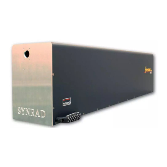
Introduction The Firestar i401 laser is a new addition to SYNRAD’s Firestar series of high power lasers. This single-tube ® 400 W laser features an integrated RF power supply with no external RF cables. The compact, single-tube design mounts easily to flatbed cutters, robotic arms, or gantry systems making integration into your produc- tion line simple and fast. -
Page 25: Unpacking
Upon arrival, inspect all shipping containers for signs of damage. If you discover shipping damage, document the damage (photographically if possible), then immediately notify the shipping carrier and SYNRAD, Inc. The shipping carrier is responsible for any damage occurring during transportation from SYNRAD, Inc. to your receiving dock. Packaging guidelines Warning Lifting or moving the Firestar i401 laser poses a potential for injury. -
Page 26: Unpacking The I401 Laser
Remove the upper lid and set it aside. Remove the top front and top rear foam inserts. To remove the center insert, first slide it forward several inches, to clear the notches in the lower foam insert, and then lift. Synrad Firestar i401 operator’s manual... -
Page 27: Removing The Lifting Handles
Figure 1-2. Save the lifting handles and capscrews so the handles can be reinstalled if the i401 is moved to another location. i401 Front View i401 Rear View Figure 1-2 Removing the i401 lifting handles Synrad Firestar i401 operator’s manual... -
Page 28: Inventory
Chiller Fittings Kit .........1 Quick Start Plug ........1 Spare Fuses (not shown) ......4 BNC Control Cable ......1 Mounting Hardware Kit ......4 Cooling Tubing ........1 Final Test Report (not shown) ....1 DC Power Cables ........1 Synrad Firestar i401 operator’s manual... -
Page 29: I401 Contents Description
Mounting Hardware Kit – fasten Firestar to your mounting surface. Four each M10 × 1.5 × 35 mm capscrews and M10 washers are provided for mounting the Firestar i401 laser. Final Test Report (not shown) – contains data collected during the laser’s final pre-shipment test. Synrad Firestar i401 operator’s manual... -
Page 30: Mounting
Refer to the Firestar i401 package outline drawing in the Technical Reference chapter for mounting locations and dimensions. Caution SYNRAD does not recommend mounting lasers in a vertical “head- down” or “tail-down” orientation. If you must mount your laser in possible this manner, please contact the factory for limitations as a vertical orientation increases the risk of damage to the laser’s output optic. -
Page 31: Figure 1-5 Firestar I401 Bottom Up Mounting Locations
Note: The i401 baseplate contains two 0.252" × 0.500" beam alignment slots (labeled “D” in Figure 1-5) and a 0.252" dowel pin hole for applications that require precision positioning of the laser. i401 Bottom View Figure 1-5 Firestar i401 bottom up mounting locations Synrad Firestar i401 operator’s manual... - Page 32 Place a split washer and flat washer on each capscrew and insert the fasteners through the mounting surface into the laser baseplate. Turn the screws by hand until the threads fully engage. Evenly tighten all four fasteners to a torque of 40 N m (29 ft lb Synrad Firestar i401 operator’s manual...
-
Page 33: Connecting
DO NOT REMOVE OR ADJUST THESE FITTINGS! damage Each laser is shipped with a cooling kit that includes 90° push-on tubing connectors to adapt the coolant fittings to your choice of standard (1/2-inch) or metric (12-mm) cooling tubing. Synrad Firestar i401 operator’s manual... - Page 34 Coolants SYNRAD recommends that the laser’s cooling fluid contain at least 90% water (distilled or tap) by volume. In closed-loop systems, use a corrosion inhibitor/algaecide such as Optishield Plus or equivalent ®...
-
Page 35: Table 1-2 Dew Point Temperatures
For example, if the air temperature is 85 °F (29 °C) and the relative humidity is 60%, then the dew point temperature is 70 °F (21 °C). Adjust the chiller’s temperature setpoint to 72 °F (22 °C) to prevent condensation from forming inside the laser. Synrad Firestar i401 operator’s manual... -
Page 36: Figure 1-6 Firestar I401 Cooling Connections
Turn on the chiller and adjust the temperature setpoint to 18 °C to 22 °C. Regulate coolant flow to 4.0 GPM at less than 60 PSI of pressure. Closely examine all cooling connections and verify that there are no leaks. Synrad Firestar i401 operator’s manual... -
Page 37: 48 V Power Supply Connections
DC power source capable of supplying a minimum of 135 A at 48 VDC. We recommend the SYNRAD PS-401 DC power supply, which can provide a maximum of 145 A at 48 VDC. AC input requirements for the PS-401 supply are 180–264/342–528 VAC, three-phase (3Ø), 30 A max per phase, 50–60 Hz. -
Page 38: Figure 1-8 Ps-401 Input Section
Input current, max. 25 Amperes per phase Wire gauge 10 AWG Fuse/circuit breaker 30 Amps To connect three-phase AC input power, refer to Figure 1-7 and perform the following steps: AC INPUT Figure 1-8 PS-401 input section Synrad Firestar i401 operator’s manual... -
Page 39: Dc Power Cables
DC OUTPUT +48 VDC POWER – VDC GROUND BUS BAR SIGNAL – VDC GROUND Vadj REMOTE SENSE SIGNAL CONNECTOR PS-401 DC Power Supply Firestar i401 Laser Figure 1-9 DC power connection locations – rear view Synrad Firestar i401 operator’s manual... -
Page 40: Figure 1-10 Dc Power Connection Locations - Side View
Connect the other end of the red (positive) cable to the +48 VDC POWER terminal on the rear of the laser. Carefully tighten the M10 bolt to a torque of 7.4 N m (5.5 ft lb ) maximum. Synrad Firestar i401 operator’s manual... -
Page 41: Control Connections
All control connections to Firestar i401 lasers are made through the 15-pin User I/O connector on the rear panel. The User I/O port receives power commands from SYNRAD’s UC-2000 Universal Laser Controller, or FH Flyer marking head, and also serves as the connection point for auxiliary signals between the laser and any parts handling, automation, or monitoring equipment. -
Page 42: Other Connections
In condensing atmospheres, a gas purge helps to reduce the potential for condensation damage. To connect the Firestar i401 gas purge port, refer to Figure 1-11 and perform the following steps: Synrad Firestar i401 operator’s manual... -
Page 43: Figure 1-11 Gas Purge Kit Assembly
Refer to Figure 1-11C and plug the filter assembly into the Gas Purge port connector. Adjust the jam nuts on the on either side of the support bracket to hold the filter assembly in posi- tion. Synrad Firestar i401 operator’s manual... -
Page 44: Table 1-4 Purge Gas Specifications
Firestar i401 lasers are pre-configured with a fixed IP address that allows a simple Ethernet connection between the i401 laser and a host. To connect your host computer to the i401 laser using a peer-to-peer Ethernet connection, perform the steps in the following sections: Synrad Firestar i401 operator’s manual... - Page 45 Follow the initial start-up procedure in the Operation chapter and proceed with Step 5 below when DC power is applied to the laser. Launch your web browser, type “http://192.168.50.50” (without the quotes,) and then press Enter. The i401 web page should appear as shown in Figure 1-12. Synrad Firestar i401 operator’s manual...
-
Page 46: Figure 1-12 Firestar I401 Web Page
To use the i401’s web page capability to monitor various operating parameters, see the Firestar i401 web interface section in the Technical Reference chapter for additional information. If you have problems connecting to the i401 web page, refer to the Troubleshooting – Web interface section in the Maintenance/Troubleshooting chapter. Synrad Firestar i401 operator’s manual... -
Page 47: Operation
This chapter contains the following information: Controls and indicators – displays and describes exterior controls and indicators on ■ Firestar i401 lasers. Initial start-up – explains how to start your Firestar i401 laser while verifying proper ■ operation. Synrad Firestar i401 operator’s manual... -
Page 48: Controls And Indicators
Optical Accessories Mounting – provides six threaded holes (8–32) for mounting optional beam de- livery components available from SYNRAD. Because excessive weight may damage the laser, consult SYNRAD before mounting components not specifically designed as Firestar options. Refer to Firestar i401 package outline drawings in the Technical Reference chapter for mounting dimensions. -
Page 49: Figure 2-2 Firestar I401 Rear Panel Controls And Indicators
DC Power Cable using the supplied M10 × 1.5 bolt at the indicated connection point. 12 Ethernet Port – provides the connection point for a TCP/IP web-based interface between your com- puter or network and the i401 laser. Synrad Firestar i401 operator’s manual... -
Page 50: Initial Start-Up
RDY LED turns Off, the SHT LED turns Off (regardless of the state of the Shutter Open Request input), and all DC power is removed from the RF boards. Synrad Firestar i401 operator’s manual... -
Page 51: With A Uc-2000 Controller
Do not use argon as a purge gas. Use only nitrogen or clean, dry air as damage described in Table 1-3, Purge gas specifications. Synrad Firestar i401 operator’s manual... - Page 52 If you are connected to the i401’s Ethernet port, access the i401 web page to verify operating condi- tions and functionality (refer back to Figure 1-12). See the Getting Started or Technical Reference chapters for details on accessing the Firestar i401 web page. Synrad Firestar i401 operator’s manual...
-
Page 53: Without A Uc-2000 Controller
Place a beam block 0.5 meters (20 in.) inches from the laser aperture to prevent the beam from trav- eling beyond the work area. Caution Inlet cooling water temperature must always be maintained above the dew point to prevent condensation and water damage to your Firestar possible laser. equipment damage Synrad Firestar i401 operator’s manual... - Page 54 LASE LED flickers. personal injury Apply a PWM Command signal (+5 VDC, 5 kHz square wave of 4 µs duration) between PWM Input (Pin 9) and PWM Return (Pin 1) on Firestar’s User I/O connector. Synrad Firestar i401 operator’s manual...
- Page 55 Shut off gas purge flow to the laser. In dirty or dusty environments; however, it may be necessary to purge the laser continuously to prevent contamination of internal optics. If your Firestar i401 laser fails to lase, refer to Troubleshooting in the Maintenance/Troubleshooting chapter for troubleshooting information. Synrad Firestar i401 operator’s manual...
- Page 56 This page intentionally left blank. Synrad Firestar i401 operator’s manual...
-
Page 57: Technical Reference
■ Firestar i401 general specifications – provides specifications for the Firestar i401 laser. ■ Firestar i401 package outline drawing – illustrates laser package outline and mount- ing dimensions for i401 lasers. ■ Packaging instructions – illustrates how to package Firestar i401 lasers for shipment. Synrad Firestar i401 operator’s manual... -
Page 58: Technical Overview
Laser design Optical resonator Firestar i401 lasers were developed using new technology developed by SYNRAD, Inc. This new technol- ® ogy, based on an hybrid waveguide/unstable resonator design (Figure 3-1), enables SYNRAD to economi- cally produce a symmetrical laser beam from a small but powerful laser capable of operating for many years with virtually no maintenance. -
Page 59: Figure 3-2 Firestar I401 Beam Ellipticity
45° to the horizontal or by using two or more mirrors. Mounting the laser at 45° is often not practical while the addition of extra mirrors in the beam path adds cost and complexity and can reduce reliability. Synrad Firestar i401 operator’s manual... -
Page 60: Rf Power Supply
Beam delivery optics Divergence, or expansion, of the laser beam is important in materials processing since a larger beam enter- ing the focusing optic produces a smaller focused spot. Synrad Firestar i401 operator’s manual... -
Page 61: Table 3-1 Assist Gas Purity Specifications
Welding High Purity Grade 99.998% purity or better Helium Welding High Purity Grade 99.997% purity or better Nitrogen Cutting/Drilling High Purity Grade 99.9500% purity or better Oxygen Cutting/Drilling Ultra Pure Grade 99.9998% purity or better Synrad Firestar i401 operator’s manual... -
Page 62: Controlling Laser Power
Operating modes Control signals Much of the information provided in this section describes the use of a SYNRAD UC-2000 Universal Laser Controller to provide PWM Command signals to the i401 laser. If using an alternate method of laser control, thoroughly review this section, Controlling laser power, as well as the following section, User I/O connections, for an understanding of the signal requirements necessary to control Firestar lasers. - Page 63 Firestar’s User I/O PWM input consists of a high-speed optoisolator LED with a forward voltage drop (Vf) of 1.5 VDC. The PWM input frequency can range from DC (0 Hz) to 100 kHz. Table 3-2 on the following page provides minimum, maximum, and nominal PWM signal specifications. Synrad Firestar i401 operator’s manual...
-
Page 64: Operating Modes
To adjust output power, refer back to the Pulse Width Modulation (PWM) sec- tion for information regarding high frequency operation. Note: SYNRAD lasers are designed for maximum performance using a 95% duty cycle. Increasing the maximum PWM percentage beyond 95% greatly increases the laser’s heat load with little or no corresponding increase in laser output power. - Page 65 While this situation can occur when using PWM Command signal frequencies of 5 kHz and less, it is im- portant to note that it isn’t the Command signal frequency itself that is the determining factor but rather this behavior happens only when the off time between PWM pulses exceeds 200 microseconds. Synrad Firestar i401 operator’s manual...
-
Page 66: User I/O Connections
Failure to do so may damage the laser. equipment damage Pin 8 Pin 1 LASE ETHERNET USER I/O Pin 15 Pin 9 Figure 3-5 User I/O connector pinouts Synrad Firestar i401 operator’s manual... -
Page 67: User I/O Connection Summary
PWM Command signal is applied to Pin 9 and Pin 1. When this output is initially switched closed, there is a five-second delay during which lasing is inhibited. This output is open (high impedance) when the laser is disabled (RDY indicator Off). Synrad Firestar i401 operator’s manual... - Page 68 This bi-directional switched output is internally connected to Pin 13, Output Common, when remote interlock circuitry is open (INT indicator illuminated red), indicating that lasing is disabled. The output is open (high impedance) when lasing is enabled (INT indi- cator green). Synrad Firestar i401 operator’s manual...
-
Page 69: Input/Output Signals
This pin is the only User I/O pin that is connected to the laser’s chassis ground. Do not use this pin for grounding if I/O circuits are powered from an external customer-supplied DC power source. Synrad Firestar i401 operator’s manual... - Page 70 Refer to Controlling laser power in this chapter for further information on laser control signals. Connect the PWM signal source return to Pin 1, PWM Return. See Table 3-4 for input circuit specifications. Synrad Firestar i401 operator’s manual...
-
Page 71: Figure 3-7 Quick Start Plug Wiring Diagram
Aux. DC Power Ground Pin 15 Pin 9 Quick Start Plug wiring diagram Figure 3-7 Figure 3-8 on the following page illustrates the input circuit’s equivalent internal schematic while Table 3-4 provides Firestar i401 input circuit specifications. Synrad Firestar i401 operator’s manual... -
Page 72: Figure 3-8 Input Equivalent Schematic
On state Vmin ±5.0 VDC @ 7 mA On state (continuous) Vmax ±24.0 VDC @ 40 mA Note: The Remote Reset/Start Request input must not be sent until Firestar’s +5 VDC power supply has stabilized (approximately 200 ms after DC power-up). Synrad Firestar i401 operator’s manual... - Page 73 Remote Interlock and Shutter Open Request signals are present (SHT LED blue and RDY LED yellow), indicating that lasing is enabled. This output is open (high impedance) when the laser is disabled (SHT LED Off). Refer to Table 3-5 for output circuit specifications. Synrad Firestar i401 operator’s manual...
-
Page 74: Figure 3-9 Output Equivalent Schematic
(13) OUTPUT COMMON 0.3 A FUSE, SELF-RESETTING Figure 3-9 Output equivalent schematic Table 3-5 Output circuit specifications Output Device Specifications Bi-directional MOSFET 2.5 Ohms Rdson 10 MOhms Off Voltage ±24 VDC, max. Current 50 mA, max. Synrad Firestar i401 operator’s manual... -
Page 75: Sample I/O Circuits
Firestar’s input circuit. USER I/O PINS Close switch to enable interlock –12 VDC (3) REMOTE INTERLOCK 0 VDC (11) INPUT COMMON Figure 3-11 Customer-supplied interlock, negative voltage Synrad Firestar i401 operator’s manual... -
Page 76: Figure 3-12 Plc Driven Interlock Signal
PLC’s output module. OUTPUT USER I/O PINS MODULE (11) INPUT COMMON (+5–24V) (2) REMOTE RESET/START REQUEST (3) REMOTE INTERLOCK (10) SHUTTER OPEN REQUEST Figure 3-13 Multiple PLC driven inputs Synrad Firestar i401 operator’s manual... -
Page 77: Figure 3-14 Firestar Output Driving Warning Lamp
Firestar outputs. USER I/O PINS (5) +24 VDC AUXILIARY POWER (6) LASER ACTIVE (12) AUX.DC POWER GROUND (13) OUTPUT COMMON Figure 3-15 Firestar output driving relay Synrad Firestar i401 operator’s manual... -
Page 78: Figure 3-16 Firestar Output Driving Plc Input Module
PLC inputs. INPUT USER I/O PINS MODULE (13) OUTPUT COMMON (+5–24V) (6) LASER ACTIVE (7) FAULT DETECTED (8) LASER READY (14) SHUTTER OPEN (15) INTERLOCK OPEN Figure 3-16 Firestar output driving PLC input module Synrad Firestar i401 operator’s manual... -
Page 79: Dc Power Cables
48.0 VDC is available at the laser’s +48V POWER terminal under full-load conditions. Depending on the ad- ditional length required, you may need to use larger gauge (2/0) wire. Synrad Firestar i401 operator’s manual... -
Page 80: Firestar I401 Web Interface
LED status, RF module voltage, current, and temperature measurements using a standard web browser as shown in Figure 3-17. Figure 3-17 Firestar i401 Internet interface page Note: On initial power-up of the laser, allow five seconds for the web interface to load before accessing the web page. Synrad Firestar i401 operator’s manual... - Page 81 The Flow Sensor Temp value is not a measurement of coolant temperature and should not be used to adjust the chiller’s setpoint! Internal Tickle Setting: Indicates that tickle is active and displays the actual tickle setting. Synrad Firestar i401 operator’s manual...
-
Page 82: Accessing The I401 Web Page
Select “Use the following IP address:” and enter the following information: IP Address: 192.168.50.100 Subnet Mask: 255.255.255.0 Click OK to submit the changes. Connect to the Firestar i401 laser Remove DC power from the laser. Synrad Firestar i401 operator’s manual... -
Page 83: Changing The I401'S Ip Address
10/100 Mbps Adapter allow your networked computer to access the Firestar i401 web page over the computer’s USB port, which isolates the laser from your computer network. In this case, use a crossover Ethernet cable between the i401 laser and the USB to Ethernet adapter. Synrad Firestar i401 operator’s manual... -
Page 84: Integrating Firestar Safety Features
RDY indicator is On) and opens the physical shutter to allow lasing. Removing voltage from the Shut- ter Open Request input, causes the physical shutter to close and block the beam path, extinguishing the SHT lamp and allowing only tickle signals to reach the tube. Synrad Firestar i401 operator’s manual... -
Page 85: Remote Interlock Functions
Pin 15, Interlock Open, and Pin 13, Output Common (see Figure 3-16). This output is closed when remote interlock circuitry is open (INT LED illuminated red). The output is open (INT LED green) when interlock circuitry is closed. Synrad Firestar i401 operator’s manual... -
Page 86: Firestar I401 General Specifications
6 Measured at 99% duty cycle, 5 kHz, and 20 °C coolant temperature after 30 minute warm-up. 7 Measured at beam waist. See the laser’s Final Test Report for beam waist location. 8 Measured at 100 Hz, 10% duty cycle. 9 Measured at 48 VDC input, 100% duty cycle. Synrad Firestar i401 operator’s manual... -
Page 87: Environmental Specifications
10 Firestar i401 lasers can be operated at coolant temperatures up to 28 °C (82 °F) in order to reduce problems associated with condensation; however, this may result in decreased laser performance and/or reduced laser lifetime. 11 Published specifications guaranteed at a cooling temperature of 20 °C. Synrad Firestar i401 operator’s manual... -
Page 88: Firestar I401 Package Outline & Mounting Drawings
Firestar i401 outline & mounting drawings Figure 3-19 Firestar i401 outline & mounting dimensions Synrad Firestar i401 operator’s manual... -
Page 89: Figure 3-20 Firestar I401 Outline & Mounting Dimensions
Firestar i401 outline & mounting drawings Figure 3-20 Firestar i401 outline & mounting dimensions (mounting feet removed) Synrad Firestar i401 operator’s manual... -
Page 90: Firestar I401 Packaging Instructions
Firestar i401 packaging instructions Figure 3-21 Firestar i401 packaging instructions Synrad Firestar i401 operator’s manual... -
Page 91: Maintenance
Use information in this chapter to perform maintenance or troubleshoot your Firestar i401 laser. This chapter contains the following information: Maintenance – describes typical Firestar i401 maintenance procedures. ■ Troubleshooting – explains how to troubleshoot common Firestar i401 problems. ■ Synrad Firestar i401 operator’s manual... -
Page 92: Disabling Firestar
Caution If you operate your laser or marking head in a dirty or dusty environ- ment, contact SYNRAD about the risks of doing so and precautions possible you can take to increase the longevity of your laser, marking head, and associated optical components. -
Page 93: Storage/Shipping
When finished, cap all connectors to prevent debris from entering the cooling system. When shipping SYNRAD lasers to another facility, we highly recommend that you ship the unit in its original SYNRAD shipping container. If you no longer have the original shipping box and inserts, contact SYNRAD Customer Service about purchasing replacement packaging. -
Page 94: Troubleshooting
Finger cots or rubber gloves Powder-free Air bulb Clean air bulb Ethyl alcohol Spectroscopic or reagent grade Acetone Spectroscopic or reagent grade Lens wipe (preferred) Optical (cleanroom) quality Cotton balls or cotton swabs High-quality surgical cotton/high-quality paper-bodied Synrad Firestar i401 operator’s manual... - Page 95 Carefully examine the optic under a good light. Certain contaminants or damage such as pitting cannot be removed. In these cases the optic must be replaced to prevent catastrophic failure. Repeat Steps 4 through 6 as required, removing all traces of contaminants and deposits. Synrad Firestar i401 operator’s manual...
-
Page 96: Introduction
This section is designed to help isolate problems to the module level only. Problems on circuit boards or the laser tube are outside the scope of this guide because they are not user-serviceable assemblies; do not attempt to repair them. Contact SYNRAD or a SYNRAD Authorized Distributor for repair or replace- ment information. -
Page 97: Operational Flowchart
Apply tickle pulses or a SHT indicator PWM Command signal Flashing? (< 5% duty cycle) for 30 to 60 seconds LASE indicator illuminates Red to indicate laser output Figure 4-1 Firestar i401 operational flowchart Synrad Firestar i401 operator’s manual... -
Page 98: Functional Block Diagram
Troubleshooting Functional block diagram Figure 4-2 is a functional block diagram illustrating the i401’s control architecture. Figure 4-2 Firestar i401 functional block diagram Synrad Firestar i401 operator’s manual... -
Page 99: Status Leds
Table 4-3 (on the following page) illustrates the dependencies of various operating parameters based on the state of the Remote Interlock input. The conditions shown in bold are those required for lasing to be enabled. Synrad Firestar i401 operator’s manual... -
Page 100: Table 4-4 Normal Operating Condition
LED Status Signal Name User I/O Signal Status Green Interlock Open Open Green Fault Detected Open Yellow Laser Ready Closed Blue Shutter Open Closed LASE (Tickle only) Laser Active Open LASE (PWM applied) Laser Active Closed Synrad Firestar i401 operator’s manual... -
Page 101: Table 4-5 Quick Start Plug Or Interlock/Shutter Inputs Not
LED Indicator LED Status Signal Name User I/O Signal Status Green Interlock Open Open Fault Detected Closed Laser Ready Open Shutter Open Open LASE (Tickle only) Laser Active Open LASE (PWM applied) Laser Active Open Synrad Firestar i401 operator’s manual... -
Page 102: Laser Fault Indications
SHT LED flashes continuously until the gas breaks down into a plasma state. Table 4-10 on the following page lists error codes, the corresponding fault, and describes basic corrective action. See the following section, Resetting faults, for detailed corrective actions. Synrad Firestar i401 operator’s manual... -
Page 103: Resetting Faults
On i401 lasers, a remote interlock condition is not latched. Re-establish the Remote Interlock signal input (INT LED changes from red to green and the Interlock Open output Opens) to enable the RDY indicator and begin lasing after the five-second delay. Synrad Firestar i401 operator’s manual... - Page 104 DC power to the laser, wait 30 seconds, and then reapply power. When the RDY LED illuminates, lasing is enabled after a five-second delay. If the RF Drive Switch fault reap- pears, the laser requires service—contact SYNRAD or a SYNRAD Authorized Distributor. PWM Drive fault A PWM Drive fault indicates a problem in the laser’s internal RF circuitry and causes the RDY LED to...
-
Page 105: General Laser Fault Conditions
RDY LED to flash 5 blinks. Reset the laser by removing DC power to the laser, wait 30 seconds, and then reapply power. When the RDY LED illuminates, lasing is enabled after a five-second delay. If the DC Pre-Charge fault reappears, the laser requires service—contact SYNRAD or a SYNRAD Authorized Distributor. - Page 106 – Green Fault Detected – Closed RDY LED – Yellow Laser Ready – Closed SHT LED – Blue (Flashing) Shutter Open – Closed LASE LED – Off or Red Laser Active – Open or Closed Synrad Firestar i401 operator’s manual...
- Page 107 – Yellow Laser Ready – Closed SHT LED – Blue Shutter Open – Closed LASE LED – Off or On Laser Active – Open or Closed Possible Causes: ■ The remote interlock circuit momentarily opened. Synrad Firestar i401 operator’s manual...
-
Page 108: Web Interface
Locate your browser’s Internet Options menu and configure it to enable Java script. As shown in Figure 4-3, the Java feature is located on the Internet Options dialog’s Advanced tab (under Tools/Internet Options). The dialog boxes in your particular browser may appear differently. Synrad Firestar i401 operator’s manual... -
Page 109: Figure 4-3 Enable Java Script In Browser
Sites button. In the Trusted sites dialog, type the laser’s IP address in the Add this website to the zone: text box, and then click Add. Click Close and then click OK twice. Figure 4-4 Add IP address to list of authorized/trusted websites Synrad Firestar i401 operator’s manual... -
Page 110: Beam Delivery Optics
Because of the extremely high power density of Firestar lasers, pits or debris on the lens surface may absorb enough energy from the focused beam to crack the lens. If this happens, other optics in the beam path may be contaminated or damaged as well. Synrad Firestar i401 operator’s manual... - Page 111 A risk of exposure to toxic elements, like zinc selenide, may result when certain optical or beam delivery components are damaged. In serious the event of damage to laser, marking head, or beam delivery optics, contact SYNRAD, Inc. or the optics manufacturer for handling personal instructions. injury...
- Page 112 This page intentionally left blank. Synrad Firestar i401 operator’s manual...
- Page 113 4-4, 4-20 PWM duty cycle, 3-7 troubleshooting, 4-20–4-21 signal amplitude, 3-7 warning, 4-2, 4-21 signal specifications, 3-8 Beam diameter 3-2 Compliance 5–10 specifications, 3-30 CDRH, 5 Class 4 safety requirements, 8 Bend radius 3-23 Synrad Firestar i401 operator’s manual...
- Page 114 1-12, 1-14, 4-16 EU Directives 9 temperature setpoint, 1-13, 1-14, 4-16 Copyright information viii EU requirements 6–9 electromagnetic interference standards, 7–9 Customer Service x laser safety standards, 7 Customer-supplied interlock 3-19 RoHS compliance, 6 safety requirements, 8 Synrad Firestar i401 operator’s manual...
- Page 115 3-34 packing/unpacking, 1-3–1-5 safety features, 3-28–3-29 specifications, 3-30–3-31 Indicators and controls 2-2–2-3 storage/shipping, 4-3 Initial start-up 2-4–2-9 technical overview, 3-2–3-5 with a UC-2000 Controller, 2-5–2-7 troubleshooting, 4-6–4-21 without a UC-2000 Controller, 2-7–2-9 web interface, 3-24–3-27 Synrad Firestar i401 operator’s manual...
- Page 116 IP Address 1-23, 3-26, 4-18 from above, 1-8–1-9 changing, 3-27 from below, 1-9–1-10 Mounting bolts 1-6, 1-7, 1-8, 1-9, 1-10 Mounting hardware kit 1-6, 1-7 Keyswitch 5, 8, 1-2 Multiple PLC driven inputs, 3-20 Keyswitch functions Synrad Firestar i401 operator’s manual...
- Page 117 3-16 Laser Active, 3-11, 3-17, 4-9, 4-10, 4-11, 4-12, 4-15, 4-16, 4-17 PWM Return signal 1-19, 2-8, 3-7, 3-8 Laser Ready, 3-11, 3-17, 4-9, 4-10, 4-11, signal description, 3-11, 3-14 4-12, 4-13, 4-15, 4-16, 4-17 Synrad Firestar i401 operator’s manual...
- Page 118 RF power supply, 3-4 Technical Support x Temperature setpoint 1-12, 1-14, 2-5, 2-8, Safety features Class 4, 8 4-16 integrating, 3-28–3-29 Temp (TMP) indicator 8, 2-2, 2-6, 2-8, 3-11, 3-17, 4-9, 4-10, 4-11, 4-12, 4-14, Safety precautions 1–3 Synrad Firestar i401 operator’s manual...
- Page 119 2-5, 2-7, 2-8, 2-9, 3-7, 3-8, 3-10, 3-11, 3-12, 3-13, 3-28, 3-29, 4-9, 4-15, 4-16, 4-17 Warning aerosol dusters, 2 air contaminants, 2 definition, 1 electrical noise, 1-19, 3-7 hazardous radiation exposure, 2, 1-20 laser output, 1-19, 2-4, 2-6, 2-8, 3-6, Synrad Firestar i401 operator’s manual...
- Page 120 Synrad Firestar i401 operator’s manual...
Need help?
Do you have a question about the Firestar i401 Series and is the answer not in the manual?
Questions and answers