Sign In
Upload
Manuals
Brands
Synrad Manuals
Measuring Instruments
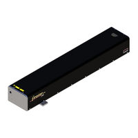
Firestar f201
Synrad Firestar f201 CO2 Laser Manuals
Manuals and User Guides for Synrad Firestar f201 CO2 Laser. We have
3
Synrad Firestar f201 CO2 Laser manuals available for free PDF download: Operator's Manual, Quick Start Manual
Synrad Firestar f201 Operator's Manual (140 pages)
Brand:
Synrad
| Category:
Measuring Instruments
| Size: 2 MB
Table of Contents
Table of Contents
3
General Hazards
13
Hazard Information
13
Other Hazards
15
Disposal
15
Additional Laser Safety Information
15
Terms
13
F100 Label Locations
16
Figure 1 Firestar F100 Hazard Label and CE Label Locations
16
F200 Label Locations
17
Figure 2 Firestar F200 Hazard Label Locations
17
F201 Label Locations
18
Figure 3 Firestar F201 Hazard Label and CE Label Locations
18
F400 Label Locations
19
Figure 4 Firestar F400 Hazard Label Locations
19
Agency Compliance
20
Center for Devices and Radiological Health (CDRH) Requirements
20
Federal Communications Commission (FCC) Requirements
21
European Union (EU) Requirements
22
Table 1 Class 4 Safety Features
23
Table 2 European Union Directives (F100)
24
Figure 5 European Compliance Mark
25
Table 3 European Union Directives (F201)
25
F100 Declaration of Conformity
26
F201 Declaration of Conformity
27
Getting Started
29
Introduction
30
Firestar Nomenclature
30
Unpacking
31
Incoming Inspection
31
Packaging Guidelines
31
Unpacking the F400 Laser
32
Figure 1-1 Unpacking the F400 Laser
32
Removing the Lifting Handles
33
Figure 1-2 Removing Lifting Handles
33
Inventory
34
F100/F201 Lasers
34
Figure 1-3 Firestar F100/F201 Shipping Box Contents
34
Table 1-1 F100/F201 Ship Kit Contents
35
F200/F400 Lasers
36
Figure 1-4 Firestar F200/F400 Shipping Box Contents
36
Table 1-2 F200/F400 Ship Kit Contents
37
Mounting
38
F100/F200 Mounting
38
Figure 1-5 Fastening F100/F200 from above
38
Figure 1-6 Fastening F100/F200 from below
39
F201/F400 Mounting
40
Figure 1-7 Improper Mounting Method
40
Figure 1-8 Fastening F201/F400 from above
40
Figure 1-9 Detail of Fastening into Mounting Surface
41
Figure 1-10 Fastening F201/F400 from below
41
Figure 1-11 Detail of Fastening into Laser
42
Connecting
43
Cooling Connections
43
Table 1-3 Dew Point Temperatures
45
Figure 1-12 Firestar F100/F201 Cooling Connections
46
Figure 1-13 Firestar F200/F400 Cooling Connections
47
PS-96 Power Supply Connections
48
Figure 1-14 PS-96 Rear View
49
Table 1-4 Three-Phase AC Electrical Recommendations
51
Table 1-5 Single-Phase AC Electrical Recommendations
52
Control Connections
53
Other Connections
56
Table 1-6 Purge Gas Specifications
56
Operation
57
Controls and Indicators
58
F100/F201 Lasers
58
Figure 2-1 Firestar F100 Controls and Indicators
58
Figure 2-2 Firestar F201 Controls and Indicators
59
F200/F400 Lasers
60
Figure 2-3 Firestar F200 Controls and Indicators
60
Figure 2-4 Firestar F400 Controls and Indicators
61
Initial Start-Up
62
With a UC-2000 Controller
62
Without a UC-2000 Controller
65
Technical Reference
69
Technical Overview
70
Laser Tube
70
Optical Resonator
70
Internal RF Power Supply
71
Optical Setup
72
Figure 3-2 "Flying Optics" Beam Path
72
Table 3-1 Assist Gas Purity Specifications
73
Controlling Laser Power
74
Control Signals
74
Figure 3-3 Typical Firestar F-Series Waveforms
75
Operating Modes
76
Figure 3-4 PWM Command Signal Waveform
76
Table 3-2 PWM Command Signal Specifications
76
User I/O Connections
79
User I/O Connection Summary
79
Table 3-3 User I/O Pin Descriptions
79
Input/Output Signals
81
Figure 3-5 User I/O Connector Pinouts
81
Figure 3-6 Auxiliary Power Supply Wiring
82
Figure 3-7 Quick Start Plug Wiring Diagram
84
Figure 3-8 Input Equivalent Schematic
85
Figure 3-9 Output Equivalent Schematic
87
Sample I/O Circuits
88
Figure 3-10 Customer-Supplied Interlock
88
Figure 3-11 Customer-Supplied Interlock, Negative Voltage
88
Figure 3-12 PLC Driven Interlock Signal
89
Figure 3-13 Multiple PLC Driven Inputs
89
Figure 3-14 Firestar Output Driving Warning Lamp
90
Figure 3-15 Firestar Output Driving Relay
90
Figure 3-16 Firestar Output Driving PLC Input Module
91
F200/F400 I/O Connections
92
Figure 3-17 Wiring Set 1 and Set 2 to Power External Circuits
92
DC Power Cables
93
F100/F200 DC Power Cables
93
F201/F400 DC Power Cables
93
Table 3-6 F100/F200 DC Power Connector Pinouts
93
Table 3-7 F201/F400 DC Power Connector Pinouts
93
Integrating Firestar Safety Features
94
Keyswitch Functions
94
Shutter Functions
95
Remote Interlock Functions
95
F100 General Specifications
96
Table 3-8 Firestar F100 General Specifications
96
F200 General Specifications
98
Table 3-9 Firestar F200 General Specifications
98
F201 General Specifications
100
Table 3-10 Firestar F201 General Specifications
100
F400 General Specifications
102
Table 3-11 Firestar F400 General Specifications
102
Figure 3-18 Firestar F100 Package Outline and Mounting Dimensions
104
Firestar F100 Package Outline Drawing
104
Figure 3-19 Firestar F200 Package Outline and Mounting Dimensions
105
Firestar F200 Package Outline Drawing
105
Figure 3-20 Firestar F201 Package Outline and Mounting Dimensions
106
Firestar F201 Package Outline Drawing
106
Figure 3-21 Firestar F400 Package Outline and Mounting Dimensions
107
Firestar F400 Package Outline Drawing
107
Figure 3-22 Firestar F100 Packaging Instructions
108
Packaging Instructions
108
Figure 3-23 Firestar F200 Packaging Instructions
109
Figure 3-24 Firestar F201 Packaging Instructions
110
Figure 3-25 Firestar F400 Packaging Instructions
111
Maintenance
113
Daily Inspections
114
Disabling F-Series Lasers
114
Cleaning Optical Components
115
Storage/Shipping
115
Table 4-1 Required Cleaning Materials
116
Introduction
118
Figure 4-1 Operational Flowchart
119
Operational Flowchart
119
Figure 4-2 F-Series Functional Block Diagram
120
Functional Block Diagram
120
Status Leds
121
Table 4-2 Status Signals
121
Table 4-3 Normal Operating Condition
122
Table 4-4 Quick Start Plug or Interlock/Shutter Inputs Not
122
Table 4-5 Interlock Open Condition
122
Table 4-6 over Temperature Fault
123
Table 4-7 Shutter Closed Condition
123
Table 4-8 VSWR Fault
123
Laser Fault Indications
124
Resetting Faults
124
Table 4-9 Laser Error Codes
124
Other Laser Faults
126
Beam Delivery Optics
129
Troubleshooting
116
Advertisement
Synrad Firestar f201 Operator's Manual (105 pages)
Brand:
Synrad
| Category:
Measuring Instruments
| Size: 3 MB
Table of Contents
Table of Contents
3
SYNRAD F201 Operator's Manual Version
8
Laser Safety
12
Figure 1-1 Labeling Terms and Definitions
13
Hazard Information
13
General Hazards
14
Other Hazards
16
Disposal
16
Additional Laser Safety Information
16
Figure 1-5 F 201 Hazard Label Locations
19
Agency Compliance
20
Center for Devices and Radiological Health (CDRH) Requirements
20
OEM Model
20
Federal Communications Commission (FCC)
21
Requirements
21
European Union (EU) Requirements
22
Figure 1-7 F201 Declaration of Conformity
26
Introduction
27
Firestar Nomenclature
27
Unpacking
27
Introduction
28
Firestar Nomenclature
28
Getting Started
28
Unpacking
29
Incoming Inspection
29
Packaging Guidelines
29
Removing the Lifting Handles
29
Figure 2-1 Unpacking the Laser
30
Figure 2-2 Removing Lifting Handles
31
F201 Lasers
32
Figure 2-3 F201 Shipping Box Contents
32
Inventory
32
Connecting
36
Cooling Connections
36
PS-96 Power Supply Connections
40
PS-96 AC Input Section
41
Control Connections
44
Other Connections
45
Operation
47
Mounting
48
Figure 3-1 F201 Controls and Indicators (Front)
48
Figure 3-2 F201 Controls and Indicators (Rear)
49
Mounting
54
Internal RF Power Supply
56
Figure 4-1 Beam Characteristics
56
Figure 4-2 "Flying Optics" Beam Path
57
Optical Setup
57
Mounting
57
Technical Overview
57
Controlling Laser Power
59
Control Signals
59
F201 Lasers
59
Figure 4-3 Typical Firestar F201 Waveforms
60
Operating Modes
61
Figure 4-4 PWM Command Signal Waveform
61
User I/O Connections
64
Input/Output Signals
65
Figure 4-5 User I/O Connector Pinouts
66
Figure 4-6 Auxiliary Power Supply Wiring
67
Figure 4-8 Input Equivalent Schematic
69
Figure 4-7 Quick Start Plug Wiring Diagram
70
Figure 4-10 Customer-Supplied Interlock
72
Figure 4-11 Customer-Supplied Interlock, Negative Voltage
72
Figure 4-12 PLC Driven Interlock Signal
73
Figure 4-13 Multiple PLC Driven Inputs
73
Figure 4-14 Firestar Output Driving Warning Lamp
74
Figure 4-15 Firestar Output Driving Relay
74
Figure 4-16 Firestar Output Driving PLC Input Module
75
DC Power Cables
76
Integrating Firestar Safety Features
77
OEM Lasers
77
Integrating Firestar Safety Features
78
Remote Interlock Functions
78
Table 4-10 Firestar F201 General
80
F201 General Specifications
80
Maintenance
83
Maintenance/Troubleshooting
84
Disabling F201 Lasers
84
Daily Inspections
84
Storage/Shipping
85
Cleaning Optical Components
85
Troubleshooting
85
Table 5-1 Required Cleaning
86
Introduction
88
Troubleshooting
88
Figure 5-1 Operational Flowchart
89
Operational Flowchart
89
Troubleshooting
89
Functional Block Diagram
90
Troubleshooting
90
Table 5-2 Status
91
Status Leds
91
Troubleshooting
91
Table 5-3 Normal Operating
92
Table 5-7 Shutter Closed
93
Table 5-9 Laser Error
94
Laser Fault Indications
94
Resetting Faults
94
Troubleshooting
94
Other Laser Faults
96
Troubleshooting
96
Beam Delivery Optics
99
Troubleshooting
99
Synrad Firestar f201 Quick Start Manual (17 pages)
laser & flyer 3D System
Brand:
Synrad
| Category:
3D Printers
| Size: 9 MB
Table of Contents
Electrical Connections
11
Control Connections
12
Cooling Connections
14
Final Preparations
17
Advertisement
Advertisement
Related Products
Synrad Firestar f series
Synrad Firestar f200
Synrad Firestar f100
Synrad Firestar f400
Synrad Firestar TI Series
Synrad Firestar V Series
Synrad Firestar Series
Synrad Firestar vi Series
Synrad Firestar i401 Series
synrad Firestar V30
Synrad Categories
Measuring Instruments
Controller
Medical Equipment
Industrial Equipment
Scanner
More Synrad Manuals
Login
Sign In
OR
Sign in with Facebook
Sign in with Google
Upload manual
Upload from disk
Upload from URL