
Subscribe to Our Youtube Channel
Related Manuals for Zhone 6519-X1


Summary of Contents for Zhone 6519-X1
- Page 1 6519-X1 (4 Port) 6518-A1 (4 Port) 6512-A1 (2-Port) 6511-A1 (1-Port) ADSL2+ Router Users Guide Document Part Number: 830-03750-01 June 2011...
- Page 2 License (“GPL”), a copy of which is available at www.gnu.org/licenses. You may obtain a copy of such software, in source code form, from Zhone for a period of three years after our last shipment of the product by following the instructions at www.zhone.com/gplinfo.
-
Page 3: Important Safety Instructions
Important Safety Instructions 1. Read and follow all warning notices and instructions marked on the product or included in the manual. 2. Slots and openings in the housing are provided for ventilation. To ensure reliable operation of the product and to protect it from overheating, these slots and openings must not be blocked or covered. -
Page 4: Ce Marking
Conformity may be downloaded from the Zhone World Wide Web site at www.zhone.com. FCC Part 15 Declaration An FCC Declaration of Conformity may be downloaded from the Zhone World Wide Web site at www.zhone.com. This device complies with Part 15 of the FCC Rules. Operation is subject to the following two conditions: (1) this device may not cause harmful interference, and (2) this device must accept any interference received, including interference that may cause undesired operation. - Page 5 exceed five (5.0). To be certain of the number of devices that may be connected to a line, as determined by the total RENs, contact the local Telephone Company. The REN for this product is part of the product identifier that has the format US:AAAEQ##TXXXX. The digits represented by ## are the REN without a decimal point.
- Page 6 CANADA - EMI NOTICE: This Class B digital apparatus meets all requirements of the Canadian interference-causing equipment regulations. Cet appareil numérique de la classe B respecte toutes les exigences du règlement sur le matérial brouilleur du Canada. NOTICE: This device complies with RSS-210,IC ID:8609A-1518A1NA Operation is subject to the following two conditions: 1) This device may not cause interference and 2) This device must accept any interference, including interference that may cause undesired...
-
Page 7: Table Of Contents
Contacting Customer Service and Technical Support..................12 Chapter 1 Introduction System Requirements ............................13 Package Contents ..............................13 Safety Instructions..............................13 Front Panels ...............................14 6519-X1 Front Panel............................14 6518-A1 Front Panel............................14 6512-A1 Front Panel............................14 6511-A1 Front Panel ............................15 LED descriptions............................15 Back Panel .................................16 Chapter 2 Hardware Installation and PC Setup Overview ................................17... - Page 8 Configuration Types ............................39 Add an ATM Layer 2 Interface ........................39 Add an Ethernet Layer 2 Interface.........................40 Add a Bridge WAN Service..........................41 Add a PPPoE WAN Service...........................41 Add an IPoE WAN Service ..........................43 Add a PPPoA WAN Service ...........................45 Add an IPoA WAN Service..........................46 Remove a Connection ...........................49 Edit a Connection............................49 Ethernet Mode..............................49...
- Page 9 Advanced ..............................116 Station Info ..............................119 Diagnostics...............................119 Fault Management ............................121 Management ..............................121 Settings ................................122 Backup Settings............................122 Update Settings ............................123 Restore Default............................123 System Log ..............................124 Configure System Log ..........................125 SNMP Agent ..............................126 TR-069 Client ..............................127 Internet Time ..............................128 Access Control ..............................129 Passwords..............................130 Services ...............................130 IP Addresses ..............................131 Update Software...............................132...
-
Page 10: About This Guide
About This Guide This guide is intended for use by installation technicians, system administrators, and network administrators. It explains how to install and configure the 6511-A1, 6512-A1 6518-A1, and 6519- X1 routers. Style and Notation Conventions The following conventions are used in this document to alert users to information that is instructional, warns of potential damage to system equipment or data, and warns of potential injury or death. -
Page 11: Typographical Conventions
CASE Brackets [ ] indicate optional syntax. Command Syntax Vertical bar | indicates the OR symbol. Acronyms The following acronyms are related to Zhone products and may appear throughout this manual: Table 1: Acronyms and their descriptions Acronym Description ADSL... -
Page 12: Contacting Customer Service And Technical Support
Wireless Fidelity (IEEE 802.11 wireless networking) Wi-Fi Multimedia Wi-Fi Protected Access Zhone Management System Contacting Customer Service and Technical Support Customer service and technical support for this Zhone device are provided by your Internet Service Provider. 65xx-A1 Family Router Users Guide... -
Page 13: Chapter 1 Introduction
Chapter 1 Introduction The 6519-X1 (four port N 2X2 router with WiFi), 6518-A1 (four port N router with WiFi), 6512-A1 (four port), and 6511-A1 (one port) ADSL 2+ routers are easily installed routers which deliver the performance needed for multimedia applications This User’s Guide will show you how to set up the routers, and how to customize the... -
Page 14: Front Panels
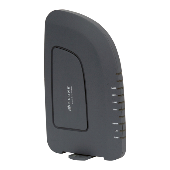
Unplug equipment first before cleaning. A damp cloth can be used to clean the equipment. Do not use liquid / aerosol cleaners or magnetic / static cleaning devices. Front Panels 6519-X1 Front Panel 6518-A1 Front Panel 6512-A1 Front Panel 65xx-A1 Family Router Users Guide... -
Page 15: 6511-A1 Front Panel
6511-A1 Front Panel LED descriptions Mode INDICATION Solid green Boot-up successful Solid red Router is booting up Power The router may not be turned on. Check if the power adapter is No light connected to the modem, the modem is plugged in and the power switch button is in the on (pushed in) state. -
Page 16: Back Panel
Back Panel NOTE: The below port descriptions are listed as they appear on the back panel from left to right. Port Description RJ-11 cable connects to incoming DSL line RJ-45 connects the unit to an Ethernet device such as a PC or a LAN1 –... -
Page 17: Chapter 2 Hardware Installation And Pc Setup
Chapter 2 Hardware Installation and PC Setup Overview This chapter provides basic instructions for connecting the router to a computer or a LAN and to the Internet using DSL. The first part provides instructions to set up the hardware, and the second part describes how to prepare your PC for use with the router. -
Page 18: Mounting The Router
Connect the Power Adapter Complete the process by connecting the AC power adapter to the POWER connector on the back of the device and plug the adapter into a wall outlet or power strip. Then turn on and boot up your PC and any LAN devices, such as hubs or switches, and any computers connected to them. -
Page 19: Unit Dimensions
Unit dimensions Model Unit Dimensions Mounting Holes 1.30" (H) x 7.25" (W) x 5" (D) 2 holes- 5.375" (136.63mm) apart 6511-A1 34.93 mm (H) x 184.15mm (W) x 127mm 1.25"(H) x 8.25" (W) x 4.75" (D) 2 holes 6.125" (155.58mm) apart 6512-A1 31.75 mm (H) x 209.55 mm (W) x 102.65... -
Page 20: Configuring Your Computer
1.25" (H) x 8.25" (W) x 4.75" (D) 2 holes 6.125" (155.58mm) apart 6519-X1 31.75 mm (H) x 209.55 mm (W) x 102.65 Configuring Your Computer Prior to accessing the router through the LAN or the USB port, note the following necessary configurations—... -
Page 21: Windows Xp
Windows XP In the Windows taskbar, click the Start button and point to Settings and then click Network Connections. In the Network Connections window, right click on the Local Area Connection icon and click on Properties. Listed in the Local Area Connection window are the installed network components. Make sure the box for Internet Protocol (TCP/IP) is checked and then click Properties. -
Page 22: Chapter 3 The Web User Interface
Chapter 3 The Web User Interface The 65xx-A1 family of combination modem/routers have a Wide Area Network (WAN) connection which connects to your phone line. This connects to your Internet Service Provider (ISP) via the phone line. The Local Area Network (LAN) connections are where you plug in your local computers to the router. -
Page 23: Summary
Enter your user name and password, and then click on OK to display the user interface. The user name / password are admin / admin and both are case sensitive. Note: For security reasons you should change your password as soon as possible. Note: There are three default user name and password combinations;... -
Page 24: Wan
Display the WAN status report from the router by clicking WAN under Device Info. The graphic below shows the screen when a WAN connection is set up. LAN Statistics Display LAN statistics by clicking LAN under Statistics 65xx-A1 Family Router Users Guide... -
Page 25: Wan Statistics
WAN Statistics Display WAN statistics by clicking WAN Service under Statistics. xTM Statistics Display ATM statistics by clicking xTM under Statistics. 65xx-A1 Family Router Users Guide... -
Page 26: Xdsl Statistics
xDSL Statistics Display ADSL statistics by clicking xDSL under Statistics. Information contained in this screen is useful for troubleshooting and diagnostics of connection problems. ADSL BER Test The ADSL Bit Error Rate (BER) test determines the quality of the ADSL connection. The test is performed by transferring idle cells containing a known pattern and comparing the received data with this known pattern to check for any errors The BER Test reflects the ratio of error bits to the total number transmitted. -
Page 27: Route
If you click on the ADSL BER Test button at the bottom of the ADSL Statistics page, the following pop-up screen will appear allowing you to set the tested time and to begin the test. To run a BER test: On the bottom of the xDSL statistics page, click xDSL BER Test In the Tested Time (sec) drop down, select the test duration, and then click Start. -
Page 28: Arp
Display the ARP status report by clicking ARP under Device Info. ARP (Address Resolution Protocol) maps the IP address to the physical address, labelled HW Address (the MAC address) and identifies computers on the LAN. DHCP Display the DHCP lease information by clicking DHCP under Device Info. DHCP (Dynamic Host Control Protocol) allows the modem to automatically assign IP addresses, to connected devices. - Page 29 65xx-A1 Family Router Users Guide...
-
Page 31: Chapter 4 Quick Setup
Chapter 4 Quick Setup The Automatic Configuration feature will automatically detect the first usable PVC and automatically detect PPPoE, PPPoA, and Bridge Protocol (with DHCP Server available). To use the Automatic Configuration feature you check the Automatic Configuration option. Note: In order for the automatic configuration to work, all previously defined WAN configurations must be removed. -
Page 32: Quick Setup With Automatic Configuration Disabled
Enter the SSID.(6518/6519 only) Click Apply/Save. You will see a progress screen When the connection is complete you will see the Service Setup summary screen. Quick Setup with Automatic Configuration Disabled From the navigation pane on the left select Quick Setup. 65xx-A1 Family Router Users Guide... - Page 33 Specify the VPI and VCI as directed by your ISP. Select the Encapsulation Mode as directed by your ISP. Under WAN Service Configuration select the protocol for the WAN connection from the Protocol dropdown as directed by your ISP. Depending on the protocol selected further parameters are presented. For example, if you selected PPPoE or PPPoA, the PPP Username and Password option appears.
- Page 34 For PPPoE, if desired, the DSL Router can be configured with a static IP address and Subnet Mask for the LAN interface to correspond to your LAN’s IP Subnet. To use a static IP address check the Use Static IP Address option, then enter the IP Address, Subnet Mask, Default Gateway and DNS server.
- Page 35 65xx-A1 Family Router Users Guide...
- Page 36 IPoA: For IPoA your ISP will supply information for IP Address, Subnet Mask, and DNS server. 65xx-A1 Family Router Users Guide...
- Page 37 DHCP: With the DHCP option you do not set any other options. Bridge: With the Bridge option you do not set any other options. 65xx-A1 Family Router Users Guide...
- Page 38 With Quick Setup the router’s wireless option is automatically set up and you will need to enter the SSID. (6518/6519 only) Click Apply/Save to save your settings. Upon completion the summary page will be displayed. 65xx-A1 Family Router Users Guide...
-
Page 39: Advanced Setup
Chapter 5 Advanced Setup This section contains advanced setup settings. To create a connection you need to define the Layer 2 interface and the WAN service. Configuration Types ADSL is an ATM based technology. The 65xx family of routers support Bridging and Ethernet over ATM (EoA) configurations and ATM based configurations: •... -
Page 40: Add An Ethernet Layer 2 Interface
For the EoA options you may select a connection mode: Default Mode: a single service over the one connection VLAN MUX Mode: multiple VLAN services over the one connection From the Encapsulation Mode drop down select the appropriate option: For EoA options (PPPoE, IPoE, Bridge) select LLC/SNAP BRIDGING For PPPoA select VC/MUX For IPoA select LLC/SNAP ROUTING From the Service Category drop down select the type of service... -
Page 41: Add A Bridge Wan Service
In the left hand menu pane, click Advanced Setup. Under Advanced Setup, click Layer2 Interface then ETH Interface, then click the Add button. Select an Ethernet port to use as a WAN interface. Select a connection mode: Default Mode: a single service over the one connection VLAN MUX Mode: multiple VLAN services over the one connection Click Apply/Save to add the appropriate WAN service. - Page 42 PPP Password: The password assigned by your ISP. Note: If you set the username/password to default/default, the modem will redirect the user to a web page within the modem to change their password when they first log on. PPPoE Service Name: Server name of network ISP. No need to set. Authentication Method: Authentication mode of network ISP.
-
Page 43: Add An Ipoe Wan Service
Address text box which is displayed when the Use Static IPv4 Address check box is selected. Enable PPP Debug Mode: Used to debug PPPoE issues. Use only when instructed by your ISP. Enable KeepAlive: Enables/disables TCP keep alive packets. KeepAlive Timer: When Enable KeepAlive is selected, this input box indicates how often the device should send keep alive packets. - Page 44 On the WAN Service Interface Configuration page, select the DSL link associated with the IPoE interface from the drop down, then click Next On the WAN Service Configuration page, select IP over Ethernet. On the WAN Service Configuration page, enter a name if you wish to customize the description shown for the service, then click Next.
-
Page 45: Add A Pppoa Wan Service
In the Wide Area Network (WAN) Service Setup page, you will see the new WAN interface added. Add a PPPoA WAN Service Add a PPPoA Layer 2 interface as described above (Add a Layer 2 Interface). Under Advanced Setup click WAN Service then click Add On the WAN Service Interface Configuration page, select the DSL link associated with the PPOA interface from the drop down, then click Next On the WAN Service Configuration page, enter a name if you wish to customize the... -
Page 46: Add An Ipoa Wan Service
Enable KeepAlive: Enables/disables TCP keep alive packets. KeepAlive Timer: When Enable KeepAlive is selected, this input box indicates how often the device should send keep alive packets. Max Fail: Number of times the router should re-attempt PPPoA authentication after a failure. - Page 47 Enable NAT must be checked for Fullcone NAT to be used. Enable Fullcone NAT: RFC 3489 defines four types of Network Address Translation (NAT). Fullcone NAT. As with other types of NAT there is a mapping from a public IP address to a private IP address.
- Page 48 WAN Setup — Summary When the settings are complete, the next screen shows a WAN Setup – Summary screen displaying the WAN configurations made. Make sure that the settings on the WAN Setup - Summary screen match the settings provided by your ISP. If all settings are correct, click the Apply/Save button to save these settings;...
-
Page 49: Remove A Connection
Remove a Connection If you want to delete a connection from the listed WAN setup, click the Remove check box next to the connection, then click Remove. Edit a Connection If you want to modify a connection from the listed WAN setup, click the Edit button next to the connection. - Page 50 If you want the DHCP server to automatically assign IP addresses, then enable the DHCP server and enter the range of IP addresses that the DHCP server can assign to your computers. Disable the DHCP server if you would like to manually assign IP addresses. Static IP Lease list –...
-
Page 51: Nat
To remove the Static IP address, click the check box next to the MAC address and click Remove Entries. You may be able to assign a second IP address for the router. To do that, click the check box Configure the second IP Address and enter the IP address and subnet mask. Click the Apply/Save button to save the LAN configuration data. - Page 52 Either select a service (by using the Select a Service dropdown) or select a custom server (by entering the IP address of the server in the Custom Server text box). You can select a Service or make a new one. Enter the IP address of the LAN side PC in the Server IP Address text box.
-
Page 53: Port Triggering
Port Triggering Click Add to add Port Triggering to your Internet application. 65xx-A1 Family Router Users Guide... -
Page 54: Dmz Host
The NAT – Port Triggering screen appears when you click Add allowing you to select the application that you want to set the port settings for. After you make your selection, click Save / Apply to save your settings. The NAT – Port Triggering Setup screen appears after you save your selections. You will be able to add or remove selections made by clicking on the Add and Remove buttons. -
Page 55: Alg
ALG, Application Layer Gateway can be used to allow firewall traversal of certain protocols. To enable protocol packets to successfully pass through firewalls and NAT, select the protocol enabled checkbox. Security For security reasons, firewall options can be configured only from the LAN side of the router. IP Filtering—Outgoing Outgoing IP filters block LAN traffic from entering the WAN side. -
Page 56: Ip Filtering-Incoming
The Add IP Filter -- Outgoing screen will appear. Add the filter name, source information (from the LAN side), and destination information (from the WAN side). Then click Save / Apply. When you Save / Apply the IP filter, the Outgoing IP Filtering Setup screen appears. The Outgoing IP Filtering Setup screen lists the outgoing IP filters, including filters which were added from the previous screen. - Page 57 Enter a filter name, information about the source address (from the WAN side), and information about the destination address (to the LAN side). Select the protocol and WAN interface to apply the filter to, then click Save/Apply to add the setting. You can view and delete the incoming filter settings in the Add Ip Filter -- Incoming screen.
- Page 58 When you Save / Apply the IP filter, the Incoming IP Filtering Setup screen appears. The Incoming IP Filtering Setup screen lists the incoming IP filters, including filters which were added from the previous screen. You can view, add or delete incoming filters. The Remove button appears only when you have an existing IP filter already set up.
-
Page 59: Mac Filtering
MAC Filtering MAC filtering can forward or block traffic by MAC address. You can change the policy or add settings to the MAC filtering table in the MAC Filtering Setup screen. To add a setting to the MAC filtering table, then click Add to access the Add MAC Filter screen, then configure the MAC filter. - Page 60 • WAN Interfaces: defines the WAN interface for this filter. This drop down list will show all the available WAN interfaces. Click Save/Apply to save the MAC filter. When you Save / Apply the IP filter, the MAC Filtering Setup screen appears. The MAC Filtering Setup screen lists the MAC filters, including filters which were added from the previous screen.
-
Page 61: Parental Control
Parental Control Use the Parental Control feature to restrict the days and times a particular device is allowed to access the Internet. Time Restriction To setup parental controls: Click Add to set up the restrictions. 65xx-A1 Family Router Users Guide... - Page 62 The Add Parental Control screen appears. Enter a User Name to identify the target of the restrictions. . This is equivalent to the host name of the IP clients (refer to the DHCP status screen check to see the host names) Enter the MAC address of the network adapter to be restricted, and, optionally, another MAC address.
-
Page 63: Url Filter
Select the days of the week the restriction is in force. Specify the start and end times the restriction is in force. Use the form hh:mm, where 23:59, for example, is one minute before midnight. Click Save / Apply to save the settings and to continue. URL Filter Access to websites can be blocked by creating a URL filter. -
Page 64: Quality Of Service
Quality of Service You can configure the Quality of Service to apply different priorities to traffic on the router. Queue Config In the QoS -- Queue Management Configuration page you can enable a queue for a network interface. Each interface associated with QoS is allocated three queues. Lower Queue Precedence values denote a higher priority for the queue, so “1”... - Page 65 Differentiated Services Code Point (DSCP) is a means to classify packets in the IP header of the packet. To associate an interface with QoS: From the Queue Config page, click Add. In the QoS Queue Configuration page enter the name of the queue and enable the queue by selecting Enable from the Queue Configuration Status drop down.
-
Page 66: Qos Classification
Click Save/Apply. QoS Classification You can configure the Quality of Service to apply different priorities to traffic on the router. The Add Network Traffic Class Rule screen allows you to add a network traffic class rule. 65xx-A1 Family Router Users Guide... - Page 67 To add a rule: In the Quality of Service—QoS Classification screen, click Add. In the Add Network Traffic Class Rule screen give a name to this traffic class. Specify a Rule Order and enable the rule in the Rule Status. Enter Classification Criteria: •...
-
Page 68: Routing
Type selected, options for the traffic rule will change. • Mark 802.1p Priority. 802.1p priority. • Tag VLAN ID: VLAN ID. Click Save / Apply to save the settings. Routing Under the Routing heading you assign a default gateway, create a routing table (in Static Route), create routing policy rules, and activate Routing Information Protocol (RIP) on the device. -
Page 69: Static Route
If you change the automatic assigned default gateway address, you must reboot the router to be assigned a new default gateway IP address. Static Route To add a routing table use the Static Route page. A maximum of 32 entries can be configured. Click Add. -
Page 70: Policy Route
Enter the route information and then click Apply/Save. Policy Route The policy routing feature allows the administrator to have more control over how packets should flow through the modem and into their networks. The feature allows administrator to route IP packets according to their Source Interface;... - Page 71 To add a policy routing rule: Click Add. Enter a unique name for the rule in the Policy Name text box. Select the interface to associate with the rule from the Use Interface drop down Select the appropriate protocol and define other parameters for the routing rule: •...
-
Page 72: Rip
• UDP/TCP Source or Destination port. • Gateway address or Interface (These can be Active PVCs or Port Mapping Groups) Click Save/Apply. To enable RIP on an interface, open the Routing – RIP Configuration page. Enter the RIP configuration and then click Apply/Save. The DNS Server Configuration configures the DNS server settings for your router. -
Page 73: Dynamic Dns
Dynamic DNS This screen allows you to enable dynamic DNS service. To configure the DDNS, click Add, then select the DDNS provider from the drop down list and enter the information provided by the DDNS . 65xx-A1 Family Router Users Guide... -
Page 74: Dsl
The DSL settings page contains sections—modulation and capability—that should be specified by your ISP. Consult with your ISP to select the correct settings for each. Click on Save / Apply if you are finished or click on Advanced Settings if you want to configure more advanced settings. -
Page 75: Capability
• G.dmt Enabled • G.lite Enabled • T1.413 Enabled • ADSL Enabled • Annex L Enabled • ADSL2+ Enabled • AnnexM Enabled Do not change this setting unless so directed by your ISP. Capability The following are included under Capability: •... - Page 76 Click Tone Selection. The frequency band of ADSL is split up into 256 separate tones, each spaced 4.3125 kHz apart. With each tone carrying separate data, the technique operates as if 256 separate modems were running in parallel. The tone range is from 0 to 31 for upstream and from 32 to 255 for downstream.
-
Page 77: Upnp
UPnP Universal Plug and Play (UPnP) is used to connect devices such as game consoles or printers that are on the same subnet. Game consoles such as xBox or PS3 which requires network connections can use UPnP to be connected to the Internet. DNS Proxy By default the router has a Domain Name Service (DNS) running. -
Page 78: Print Server (6519 Only)
In the Host name of the Broadband Router text box enter the Host Name for the DNS Server to be used. In the Domain name of the LAN network text box enter the domain name of the local network. Click Save / Apply. Print Server (6519 ONLY) Enable or disable a printer server on the router. -
Page 79: Windows 7
Windows 7 In the Advanced Setup > Print Setup screen, add the printer. In this example, the printer name is CanonMP250. 65xx-A1 Family Router Users Guide... - Page 80 The following example uses a router IP Address as 192.168.1.254, as shown in the LAN Setup page. Normally, the router default IP address is 192.168.1.1. From the Control Panel, Hardware and Sound > Devices and Printers screen click Add a Printer.
- Page 81 Click Add a Network, Wireless or Bluetooth printer, the click Next. The system will search for available printers. Click The printer that I want isn’t listed. Select Add a printer using a TCP/IP address or hostname, then click Next. Enter the address of the printer. 65xx-A1 Family Router Users Guide...
- Page 82 For example: http://192.168.1.254:631/printers/CanonMP250 and click Next. The syntax is http://<modem_IP_Address>:<Port ID>/printers/<Printer_Name> Where <modem_IP_Address> is the Modem LAN IP Address, the default IP Address is 192.168.1.1 <Port_ID>: fixed at 631 <Printer_Name> must be the same name entered in the modem Printer Server Setting as described in Step 1.
-
Page 83: Windows Xp
In the Install the printer driver screen, select the Manufacturer of the printer and Printer model name, then click Next. Specify whether you want to share the printer and enter a printer name, if desired. Click Finish. Check the status of printer from Windows Control Panel, Hardware and Sound > Devices and Printers window. - Page 84 65xx-A1 Family Router Users Guide...
- Page 85 The following example uses a router IP Address as 192.168.1.254, as shown in the LAN Setup page. Normally, the router default IP address is 192.168.1.1. Click Add a Printer from the Printers and Faxes Control Panel computer, then click Next. Select Network Printer and click Next.
- Page 86 Select Connect to a printer on the Internet and enter the IP address of the printer. For example: http://192.168.1.254:631/printers/CanonMP250 and click Next. The syntax is http://<modem_IP_Address>:<Port ID>/printers/<Printer_Name> Where <modem_IP_Address> is the Modem LAN IP Address, the default IP Address is 192.168.1.1 <Port_ID>: fixed at 631 <Printer_Name>...
- Page 87 Chose the Manufacturer of the printer and Printer Model Name then click Next. Choose Yes or No for default printer setting and click Next. 65xx-A1 Family Router Users Guide...
- Page 88 Click Finish. Check the status of printer from Windows Control Panel, printer window. Status should be Ready. 65xx-A1 Family Router Users Guide...
-
Page 89: Interface Grouping
Interface Grouping The interface group feature allows you to open ports to allow certain Internet applications on the WAN side to pass through the firewall and enter your LAN. To use this feature, mapping groups should be created. To create a new mapping group: Click Add button If you need to edit an entry, then click Edit for that group. - Page 90 After clicking the Add button, the Port Mapping Configuration screen appears Enter a unique Group name. 65xx-A1 Family Router Users Guide...
-
Page 91: Lan Ports
Select interfaces from the available interface list and add them to the grouped interface list using the arrow buttons to create the required mapping of the ports. Click Save/Apply. LAN Ports Enable/disable virtual LANs. Virtual LANs are used to enhance security and manage traffic going to different networks. - Page 92 Click Add New Connection to access the IPSec Settings screen to enter your configurations. 65xx-A1 Family Router Users Guide...
- Page 93 65xx-A1 Family Router Users Guide...
- Page 94 The Show Advanced Settings button at the bottom of the screen provides additional encryption settings. 65xx-A1 Family Router Users Guide...
-
Page 95: Certificate
Certificate Use the Certificate screen to add, view, or remove a certificate for use by a peer to verify your identity. A maximum of four certificates can be stored. You can add a certificate either by creating a new one or importing an existing one from a location where one is stored. Note: Certificates are used with TR-069. - Page 96 Follow the screens that appear to configure a new certificate. Click Apply to submit the request. If you have a certificate already, you can simply import the certificate by pasting the certificate content and private key into the space provided. If you have an existing certificate, click on Import Certificate to retrieve it.
- Page 97 65xx-A1 Family Router Users Guide...
-
Page 98: Trusted Ca
Trusted CA The trusted certificate authority (CA) allows you to verify the certificates of your peers. The Trusted CA (Certificate Authority) Certificates screen also allows you to view certificates. You can store up to 4 certificates. To Import a certificate: Click on Import Certificate Enter the certificate name in the Certificate text box. - Page 99 In the Certificate text window paste the content of the certificate. Click Apply. 65xx-A1 Family Router Users Guide...
-
Page 100: Multicast
Multicast The Multicast screen allows you to configure IGMP settings for multicast. 6518/6519 only Wireless ( The router’s wireless feature can be configured to your needs. Sections covered under the wireless section include • Basic • Security • MAC filter •... - Page 101 65xx-A1 Family Router Users Guide...
-
Page 102: Security
Security The Wireless – Security screen allows you to select the network authentication method and to enable or disable WPS (WiFi Protected Setup). Note that depending on whether WPS is enabled and the network authentication method that is selected, the screen will change accordingly so additional fields can be configured for the specific authentication method. -
Page 103: Manual Setup Ap
Manual Setup AP Network authentication methods include the following. 65xx-A1 Family Router Users Guide... - Page 104 • Open — anyone can access the network. The default is a disabled WEP encryption setting 65xx-A1 Family Router Users Guide...
- Page 105 • Shared — WEP encryption is enabled and encryption key strength of 64-bit or 128-bit needs to be selected. Click on Set Encryption Keys to manually set the network encryption keys. Up to 4 different keys can be set and you can come back to select which one to use at anytime. 65xx-A1 Family Router Users Guide...
- Page 106 • 802.1X — requires mutual authentication between a client station and the router by including a RADIUS-based authentication server. Information about the RADIUS server such as its IP address, port and key must be entered. WEP encryption is also enabled and the encryption strength must also be selected.
- Page 107 • WPA (Wi-Fi Protected Access) — usually used for the larger Enterprise environment, it uses a RADIUS server and TKIP (Temporal Key Integrity Protocol) encryption (instead of WEP encryption which is disabled). TKIP uses128-bit dynamic session keys (per user, per session, and per packet keys).
- Page 108 • WPA-PSK (Wi-Fi Protected Access – Pre-Shared Key) — WPA for home and SOHO environments also using the same strong TKIP encryption, per-packet key construction, and key management that WPA provides in the enterprise environment. The main difference is that the password is entered manually. A group re-key interval time is also required. 65xx-A1 Family Router Users Guide...
- Page 109 • WPA2 (Wi-Fi Protected Access 2) — second generation WPA which uses AES (Advanced Encryption Standard) instead of TKIP as its encryption method. Network re-authorization interval is the time in which another key needs to be dynamically issued. 65xx-A1 Family Router Users Guide...
- Page 110 • WPA2-PSK (Wi-Fi Protected Access 2 – Pre-Shared Key) — suitable for home and SOHO environments, it also uses AES encryption and requires you to enter a password and a re-key interval time. 65xx-A1 Family Router Users Guide...
- Page 111 • Mixed WPA2 / WPA — useful during transitional times for upgrades in the enterprise environment, this mixed authentication method allows “upgraded” and users not yet “upgraded” to access the network via the router. RADIUS server information must be entered for WPA and a as well as a group re-key interval time.
-
Page 112: Mac Filter
• Mixed WPA2 / WPA-PSK — useful during transitional times for upgrades in the home or SOHO environment, a pre-shared key must be entered along with the group re-key interval time. Both TKIP and AES are also used. MAC Filter By default, MAC filter is disabled meaning any WiFi clients with the correct access will be allowed to access the Access Point. - Page 113 To add a MAC Filter: In the Wireless — MAC Filter page, select the SSID to apply the filter to. From one of the MAC Restrict Mode radio buttons, select Disabled, Allow or Deny. Click Add. In the Wireless - MAC Filter screen enter the MAC address in the MAC Address text box, then click Save/Apply.
-
Page 114: Wireless Bridge
Wireless Bridge In the Wireless — Wireless Bridge screen, you can select the mode for the router, either access point or wireless bridge. If you enable the bridge restrict option, then proceed to enter the MAC addresses of the remote bridges. To restrict a wireless bridge: In the Wireless —... - Page 115 65xx-A1 Family Router Users Guide...
-
Page 116: Advanced
Advanced The Advanced page configures advanced features of the wireless LAN interface. Note: Do not change the settings on this screen if you are not familiar with WiFi settings 65xx-A1 Family Router Users Guide... - Page 117 Advanced features include: • Band — a default setting at 2.4GHz – 802.11g • Channel — 802.11b and 802.11g use channels to limit interference from other devices. If you are experiencing interference with another 2.4Ghz device such as a baby monitor, security alarm, or cordless phone, then change the channel on your router.
- Page 118 • Basic Rate — the set of data transfer rates that all the stations will be capable of using to receive frames from a wireless medium. • Fragmentation Threshold—used to fragment packets which help improve performance in the presence of radio frequency (RF) interference. •...
-
Page 119: Station Info
Station Info The Station Info page shows stations that have been authorized access to the router through its wireless function. Diagnostics The diagnostics screen allows you to run diagnostic tests to check your DSL connection. The outcome will show test results of three connections: •... - Page 120 65xx-A1 Family Router Users Guide...
-
Page 121: Fault Management
Fault Management The diagnostics screen allows you to run diagnostic tests to check your PTM VDSL connection. • Maintenance Domain— Determine the device that receives and passes through the CFM (Connectivity Fault Management) frame. • Destination MAC Address—Destination MAC address (where the fault detection packets will be sent). -
Page 122: Settings
Settings Backup Settings To save a copy of the configurations that you have made on your router: From the Settings – Backup page click Backup Settings. The below pop-up screen will appear with a prompt to open or save the file to your computer. -
Page 123: Update Settings
Update Settings To load a previously saved configuration file onto your router: From the Settings – Update Settings page, click Browse to find the file on your computer. Click Update Settings. The router will restore settings and reboot to activate the restored settings. Restore Default Restore Default will delete all configuration changes you have made and restore the router to factory default settings. -
Page 124: System Log
The router will restore the default settings and reboot. System Log The System Log dialog allows you to view the System Log and configure the System Log options. To view the System Log click View System Log to check the log file. Note: Only configure this if you are instructed by your ISP technician during troubleshooting sessions. -
Page 125: Configure System Log
The System Log page shows the date and time of the recorded event, which facility captured the event, the severity of the event and a message which describes the event. Configure System Log If the log is enabled, the system will log selected events based on their level. The log levels are •... -
Page 126: Snmp Agent
If the selected mode is Remote or Both, events will be sent to the specified IP address and UDP port of a remote system log server. If the selected mode is Local or Both, events will be recorded in the local memory. Select the desired values and click Save/Apply button to configure the system log. -
Page 127: Tr-069 Client
TR-069 Client The router includes a TR-069 client WAN management protocol with default values configured. Note: Do not change this information unless you are instructed to by your ISP technician. To enable the TR-069 client protocol: Select Enable. 65xx-A1 Family Router Users Guide... -
Page 128: Internet Time
Click on the Save/Reboot button for the change to take place. Internet Time Your router can synchronize its internal clock servers with servers running Network Time Protocol (NTP). To enable NTP, click Automatically synchronize with Internet time servers and enter the NTP settings. -
Page 129: Access Control
Access Control You can enable or disable some services of your router by LAN or WAN. If no WAN connection is defined, only the LAN side can be configured. Note: Do not change this information unless you are instructed to by your ISP technician. 65xx-A1 Family Router Users Guide... -
Page 130: Passwords
Passwords Access the Passwords screen under the Access Control section to change a password. Select an account and enter the current password and the new password and then click on the Save / Apply button. Services Services that can be enabled or disabled on the LAN/WAN are •... -
Page 131: Ip Addresses
IP Addresses Web access to the router may be limited when Access Control Mode is enabled. Note: Do not change this information unless you are instructed to by your ISP technician. Adding or changing the settings on this page may cause you to lose management access to the router. To add the IP address to the IP address list: 65xx-A1 Family Router Users Guide... -
Page 132: Update Software
Click Add. In the Add IP Addresses screen, assign the IP address of the management station that is permitted to access the local management services, in the IP Address text box. Enter the Subnet Mask. Click Save / Apply. In the Access Control -- IP Address screen, select the IP address then select Enabled to enable Access Control Mode. -
Page 133: Reboot
Reboot Clicking Save/Reboot saves all the configurations you have made, then reboots the router using the new configuration information. Tools The Ping and Trace Route tools may be used to verify accessibility and routes. 65xx-A1 Family Router Users Guide... - Page 134 65xx-A1 Family Router Users Guide...
- Page 135 65xx-A1 Family Router Users Guide...
-
Page 136: Chapter 6 Troubleshooting
Chapter 6 Troubleshooting The Router Is Not Functional Check to see that the power LED is green and the network cables are installed correctly. Refer to the quick start guide for more details. Check to see that the LAN and Status LEDs are green. Check the settings on your PC. -
Page 137: The Dsl Led Is Always Off
The DSL LED is Always Off Make sure you have DSL service. You should receive notification from your ISP that DSL service is installed. You can usually tell if the service is installed by listening to the phone line: you will hear some high-pitched noise. -
Page 138: Tracert
On Windows-based computers, you can execute the tracert command from the Start menu. Click the Start button, and then click Run. In the Open text box, type the following: tracert www.zhone.com Nslookup You can use the nslookup command to determine the IP address associated with an Internet site name. -
Page 139: Appendix A - Glossary
Appendix A – Glossary Term Description 802.11 A family of specifications for wireless LANs developed by a working group of the IEEE. This wireless Ethernet protocol, often called Wi-Fi. 10BASE-T A designation for the type of wiring used by Ethernet networks with a data rate of 10 Mbps. - Page 140 Broadband A telecommunications technology that can send different types of data over the same medium. DSL is a broadband technology. Broadcast To send data to all computers on a network. DHCP Dynamic Host Configuration Protocol DHCP automates address assignment and management. When a computer connects to the LAN, DHCP assigns it an IP address from a shared pool of IP addresses;...
- Page 141 but if something happens to your engine, you are protected. The firewall in the router is very similar. Only the connections that you allow are passed through the firewall. These connections normally originate from the local network, such as users web browsing, checking e- mail, downloading files, and playing games.
- Page 142 Local Area Network. A network limited to a small geographic area, such as a home or small office. Light Emitting Diode An electronic light-emitting device. The indicator lights on the front of the device are LEDs. MAC address Media Access Control address The permanent hardware address of a device, assigned by its manufacturer.
- Page 143 Point-to-Point Protocol A protocol for serial data transmission that is used to carry IP (and other protocol) data between your ISP and your computer. The WAN interface on the device uses two forms of PPP called PPPoA and PPPoE. See PPPoA, PPPoE.
- Page 144 suite of protocols. Telnet An interactive, character-based program used to access a remote computer. While HTTP (the web protocol) and FTP only allow you to download files from a remote computer, Telnet allows you to log into and use a computer from a remote location. TFTP Trivial File Transfer Protocol A protocol for file transfers, TFTP is easier to use than File Transfer...
- Page 145 Virtual Path Identifier Together with the Virtual Circuit Identifier (VCI), the VPI uniquely identifies a VC. Your ISP will tell you the VPI for each VC they provide. See VC. Wide Area Network Any network spread over a large geographical area, such as a country or continent.
Need help?
Do you have a question about the 6519-X1 and is the answer not in the manual?
Questions and answers