Table of Contents
Advertisement
Advertisement
Table of Contents

Related Manuals for Zhone 6519W1


Summary of Contents for Zhone 6519W1
- Page 1 6519-W1-NA User Manual VER: 1.0...
-
Page 2: Table Of Contents
User Manual Contents Safety Precautions ................... 1 Overview ....................3 Application ..................... 3 Features ....................3 Standards Compatibility and Compliance ..........4 Hardware Description and Installation ............. 6 Hardware Description ................6 3.1.1 Front Panel ................6 3.1.2 Rear Panel and Side Panel ........... 7 Hardware Installation ................ - Page 3 User Manual 5.2.5 NAT ..................60 5.2.6 Security ................64 5.2.7 Parental Control ..............67 5.2.8 Quality of Service ..............69 5.2.9 Routing ................72 5.2.10 DNS ..................76 5.2.11 DSL ..................77 5.2.12 UPnP ................... 78 5.2.13 DNS Proxy ................79 5.2.14 Print Server .................
- Page 4 User Manual 5.5.7 Update Software ..............116 5.5.8 Reboot ................117 Q&A ...................... 118...
-
Page 5: Safety Precautions
User Manual Safety Precautions Read the following information carefully before operating the device. Please follow the following precaution items to protect the device from risks and damage caused by fire and electric power: Use volume labels to mark the type of power. Use the power adapter that is packed within the device package. - Page 6 User Manual Utilisez l'adaptateur d ’ alimentation électrique que vous trouverez dans l ’ emballage de l'appareil. Veuillez-vous assurer que la prise électrique à laquelle votre appareil sera relié ne soit pas surchargée. Une prise de courant surchargée ou endommagée peut provoquer un risque d ’...
-
Page 7: Overview
User Manual Overview The xDSL Router integrates wireless LAN, USB storage, and 3G WAN services into one unit. It is designed to provide a simple and cost-effective xDSL Internet connection for a private Ethernet and 802.11g/802.11b/802.11n wireless network. The Router combines high-speed xDSL Internet connection, IP routing for the LAN and wireless connectivity in one package. -
Page 8: Standards Compatibility And Compliance
User Manual User-friendly GUI for web configuration Several pre-configured popular games. Just enable the game and the port settings are automatically configured. Compatible with all standard Internet applications Industry standard and interoperable xDSL interface Simple web-based status page displays a snapshot of system configuration, and links to the configuration pages Downloadable flash software updates Support for up to 8 permanent virtual circuits (PVC) - Page 9 User Manual ITU G.994.1 (G.hs) ITU G.992.3 (ADSL2) ITU G.992.5 (ADSL2+) 3G (WCDMA, CDMA2000, TD-SCDMA) ANSI T1.413 Issue 2 IEEE 802.3 IEEE 802.3u IEEE 802.11b IEEE 802.11g IEEE 802.11n...
-
Page 10: Hardware Description And Installation
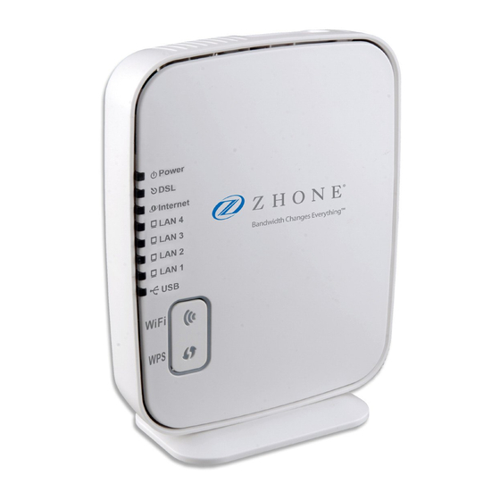
User Manual Hardware Description and Installation Note: The figures in this document are for reference only. 3.1 Hardware Description 3.1.1 Front Panel Figure 1 Front panel The following table describes the indicators on the front panel. Indicator Color Status Description The device is powered on and the device operates normally. -
Page 11: Rear Panel And Side Panel
User Manual Indicator Color Status Description The connection of 3G or USB flash disk has established. Green Blink Data is being transmitted. No signal is detected. WLAN is enabled. Data is being transmitted through the wireless WLAN Green Blink interface. WLAN is disabled. - Page 12 User Manual Figure 3 Side Figure 2 Rear panel panel The following table describes the interfaces or the buttons. Interface Description RJ-11 port: Connect the router to DSL connector or splitter through telephone cable. RJ-45 port, for connecting the router to a PC or another network LAN 4~1 device.
-
Page 13: Hardware Installation
User Manual veuillez appuyer doucement à l’aide d’une aiguille sur le bouton RESET pendant 1. L’unité redémarrera en utilisant les paramètres de configuration par défaut. 3.2 Hardware Installation 3.2.1 Choosing the Best Location for Wireless Operation Many environmental factors may affect the effective wireless function of the DSL Router. - Page 14 User Manual The followig figure displays the connection of the DSL router, PC, and telephones. Figure 4 Connecting the DSL router...
-
Page 15: Pc Network Configuration And Login
User Manual PC Network Configuration and Login 4.1 PC Network Configuration Each network interface on the PC should either be configured with a statically defined IP address and DNS address, or be instructed to automatically obtain an IP address using the network DHCP server. DSL router provides a DHCP server on its LAN and it is recommended to configure your LAN to automatically obtain its IP address and DNS server IP address. - Page 16 User Manual Figure 5 IP and DNS configuration TCP/IP configuration steps for Windows XP are as follows: Choose Start > Control Panel > Network Connections. Right-click the Ethernet connection icon and choose Properties. On the General tab, select the Internet Protocol (TCP/IP) component and click Properties.
-
Page 17: Logging In To The Dsl Router
User Manual Select the Obtain an IP address automatically radio button. Select the Obtain DNS server address automatically radio button. Click OK to save the settings. 4.2 Logging In to the DSL Router To log in to the DSL router, do as follows: Open a Web browser on your computer. -
Page 18: Web-Based Management
User Manual After logging in to the DSL router as a super user, you can query, configure, and modify all the settings, and diagnose the system. Web-Based Management This chapter describes how to use Web-based management of the DSL router, which allows you to configure and control all of DSL router features and system parameters in a user-friendly GUI. -
Page 19: Wan
User Manual This page displays the device information such as the board ID, software version, and the information of your WAN connection such as the upstream rate and the LAN address. 5.1.2 WAN Choose Device Info > WAN and the following page appears. -
Page 20: Statistics
User Manual This page displays the information of the WAN interface, such as the connection status, and the IP address. 5.1.3 Statistics 5.1.4 LAN Choose Device Info > Statistics > LAN and the following page appears. In this page, you can view the statistical information about the recevied and transmitted data packets of the Ethernet and wireless interfaces. -
Page 21: Xtm
User Manual In this page, you can view the statistical information about the recevied and transmitted data packets of the WAN interface. Click Reset Statistics to restore the values to zero and recount them. 5.1.6 xTM Choose Device Info > Statistics > xTM and the following page appears. In this page, you can view the statistical information about the recevied and transmitted data packets at the xTM interfaces. - Page 22 User Manual...
- Page 23 User Manual In this page, you can view the statistical information about the recevied and transmitted data packets of the xDSL interfaces. Click xDSL BER Test to test the xDSL Bit Error Rate. Click Reset Statistics to restore the values to zero and recount them. xDSL BER Test Click xDSL BER Test to perform a bit error rate (BER) test on the DSL line.
-
Page 24: Route
User Manual When the ADSL BER test completes, the following page appears. Note: If the BER reaches e-5, you cannot access the Internet. 5.1.8 Route Choose Device Info > Route and the following page appears. In this page, you can view the route table information. -
Page 25: Arp
User Manual 5.1.9 ARP Choose Device Info > ARP and the following page appears. In this page, you can view the MAC address and IP address information of the device connected to the router. 5.1.10 DHCP Choose Device Info > DHCP and the following page appears. In this page, you can view the host name, the IP address assigned by the DHCP server, the MAC address this is corresponding to the IP address, and the DHCP lease time. - Page 26 User Manual...
-
Page 27: Layer2 Interface
User Manual 5.2.1 Layer2 Interface 5.2.1.1 ATM Interface Choose Advanced Setup > Layer2 Interface > ATM Interface . In this page, you can add or remove to configure DSL ATM Interfaces. Click Add to add ATM Interface and the following page appears. - Page 28 User Manual In this page, you can enter this PVC (VPI and VCI) value, and select DSL link type (EoA is for PPPoE, IPoE, and Bridge.), encapsulation mode, service category. VPI (Virtual Path Identifier): The virtual path between two points in an ATM network, and its valid value is from 0 to 255.
- Page 29 User Manual DSL Link Type: EoA (it is for PPPoE, IPoE, and Bridge), PPPoA, or IPoA Encapsulation Mode: LLC/SNAP-BRIDGING, or VC/MUX Service Category: UBR Without PCR, UBR With PCR, CBR, Non Realtime VBR, Realtime VBR. Select Scheduler for Queues of Equal Precedence as the Default Queue: Weighted Round Robin or Weighted Fair Queuing.
-
Page 30: Wan Service
User Manual In this page, you can select a ETH port. Click Apply/Save to save configuration. Note: If ETH Interface is selected, there are two WAN service types (PPPoE and IPoE). 5.2.2 WAN Service Choose Advanced Setup > WAN Service, and the following page appears. In this page, you are allowed to add, remove, or edit a WAN service. - Page 31 User Manual Step2 In this page, you can select a ATM Interface for the WAN service. After selecting the ATM interface, click Next to display the following page.
- Page 32 User Manual Step3 In this page, select the WAN service type to be PPP over Ethernet (PPPoE). Click Next to display the following page.
- Page 33 User Manual Step4 In this page, you can modify the PPP username, PPP password, PPPoE service name and authentication method. PPP Username: The correct user name provided by your ISP. PPP Password: The correct password provided by your ISP. PPPoE Service Name: If your ISP provides it to you, please enter it. If not, do not enter any information.
- Page 34 User Manual Dial on demand (with idle timeout timer): If this function is enabled, you need to enter the idle timeout time. Within the preset minutes, if the modem does not detect the flow of the user continuously, the modem automatically stops the PPPoE connection.
- Page 35 User Manual Step6 In this page, select a preferred WAN interface as the system default gateway and then click Next to display the following page. Step7 In this page, you can obtain the DNS server addresses from the selected WAN interface. Click Next, and the following page appears.
- Page 36 User Manual Step8 In this page, it displays the information about the PPPoE settngs. Click Apply/Save to save and apply the settings. 5.2.2.2 Adding a MER (IPoE) WAN service This section describes the steps for adding the MER WAN service. Step1 In the Wide Area Network (WAN) Service Setup page, click the Add button to display the following page.
- Page 37 User Manual Step3 In this page, select the WAN service type to be IP over Ethernet, enter the service description for this service. After finishing setting, click Next to display the following page.
- Page 38 User Manual Step4 In this page, you may modify the WAN IP settings. You may select obtain an IP address automatically or manually enter the IP address provided by your ISP. Click Next and the following page appears. Note: If selecting Obtain an IP address automatically, DHCP will be enabled for PVC in MER mode.
- Page 39 User Manual Step5 In this page, you can set the network address translation settings,for example, enabling NAT, enabling firewall, and enabling IGMP multicast. After finishing setting, click Next and the following page appears. Step6 In this page, select a preferred WAN interface as the system default gateway and then click Next to display the following page.
- Page 40 User Manual Step7 In this page, you can obtain the DNS server addresses from the selected WAN interface. After finishing setting, click Next to display the following page.
- Page 41 User Manual Step8 In this page, it displays the information about the IPoE settngs.Click Apply/Save to save and apply the settings. 5.2.2.3 Adding a PPPoA WAN service This section describes the steps for adding the PPPoA WAN service. Step1 Choose Advanced Setup > Layer2 Interface > ATM Interface to dsipaly the DSL ATM Interface Configuration page.
- Page 42 User Manual Step2 Select the DSL link type to be PPPoA, and select the encapsulation mode to be VC/MUX (according to the uplink equipment). After finishing setting, click the Apply/Save button to apply the setings. Step3 Choose WAN Service and click Add to display the following page.
- Page 43 User Manual Step4 Select the proper interface for the WAN service, and then click Next to display the following page. Step5 In this page, you may modify the service description. Click Next to display the following page.
- Page 44 User Manual PPP Username: The correct user name provided by your ISP. PPP Password: The correct password provided by your ISP. Authentication Method: The value can be AUTO, PAP, CHAP, or MSCHAP. Usually, you can select AUTO. Enable Fullcone NAT:. NAT is one where all requests from the same internal IP address and port are mapped to the same external IP address and port.
- Page 45 User Manual dial-up. If this function is enabled, the modem uses this IP address as the WAN IP address. Enable PPP Debug Mode:Enable or disable this function. Enable IGMP Multicast Proxy: If you want PPPoE mode to support IPTV, enable it. Step6 In this page, you can enter the PPP username and PPP password provided by your ISP.
- Page 46 User Manual Step8 In this page, you can obtain the DNS server addresses from the selected WAN interface. After finishing setting, click Next to display the following page.
- Page 47 User Manual Step9 In this page, it displays the information about the PPPoA settngs.Click Apply/Save to apply the settings. You can modify the settings by clicking the Back button if necessary. 5.2.2.4 Adding an IPoA WAN service This section describes the steps for adding the IPoA WAN service. Step1 Choose Advanced Setup >...
- Page 48 User Manual Step2 Select the DSL link type to be IPoA, and select the encapsulation mode to be LLC/SNAP-ROUTING (according to the uplink equipment). After finishing setting, click the Apply/Save button to save the settings. Step3 Choose WAN Service and click Add to display the following page.
- Page 49 User Manual Step4 Select the proper interface for the WAN service ,and then click Next to display the following page. Step5 In this page, you may modify the service description. Click Next to display the following page.
- Page 50 User Manual Step6 In this page, enter the WAN IP address, the WAN subnet mask, and primary DNS server provided by your ISP and then click Next to display the following page. In this page, Network Address Translation (NAT) allows you to share one Wide Area Network (WAN) IP address for multiple computers on your Local Area Network (LAN).
- Page 51 User Manual Step7 After finishing setting, click Next to display the following page. Step8 In this page, select a preferred WAN interface as the system default gateway and then click Next to display the following page.
- Page 52 User Manual Step9 In this page, you can obtain the DNS server addresses from the selected WAN interface. After finishing setting, click Next to display the following page. Step10 In this page, it displays the information about the IPoA settngs. Click Apply/Save to save and apply the settings.
- Page 53 User Manual Step2 Select the proper ATM Interface and then click Next to display the following page.
- Page 54 User Manual Step3 In this page, you can select the WAN service type, and modify the service description for this service. After finishing setting, click Next to display the following page.
-
Page 55: Wan Service
User Manual Step4 In this page, it displays the information about the bridge settngs. Click Apply/Save to save and apply the settings. You can modify the settings by clicking the Back button if necessary. 5.2.3 3G WAN Service Choose Advanced Setup > 3G WAN Service , and the following page appears. This page is used to configure 3G connection. - Page 56 User Manual In this page, you are allowed to configure the settings of the 3G USB modem. Enable USB Modem: If you want to access the Internet through the 3G network card, you must enable the USB modem. User Name: Username provided by your 3G ISP. Password: Password provided by your 3G ISP.
- Page 57 User Manual Idle time (in sec.): If no traffic for the preset time, the 3G will disconnect automatically. Net Select: Select the 3G network that is available.You may select EVDO, WCDMA, CDMA2000, TD-SCDMA, GSM, or Auto. Dial on demand: Within the preset minutes, if the modem does not detect the flow of the user continuously, the modem automatically stops the 3G connection.
-
Page 58: Lan Configuration
User Manual connection. When the DSL WAN connection starts to perform dial-up, the 3G connection will be disconnected. If the DSL WAN connection has established, you may manually to perform 3G dial-up, and then the DSL WAN connection will be disconnected. 5.2.4 LAN Configuration Choose Advanced Setup >... - Page 59 User Manual In this page, you can configure an IP address for the DSL router, enable IGMP snooping, enable or disable the DHCP server, edit the DHCP option, configure the DHCP advanced setup and set the binding between a MAC address and an IP address.
- Page 60 User Manual Configuring the DHCP Server If you enable the DHCP sever, the clients will automatically acquire the IP address from the DHCP server. If the DHCP server is disabled, you need to manually set the start IP address, end IP address and the lease time for the clients in the LAN. Editing the DHCP Option60 Click the Edit DHCP Option60 button in the Local Area Network (LAN) Setup page to display the DHCP Option60 Setup page.
- Page 61 User Manual DHCP Advanced Setup Click the DHCP Advance Setup button in the Local Area Network (LAN) Setup page to display the following page. In this page, you can enable or disable DHCP for every LAN interface. Configuring the DHCP Static IP Lease List The lease list of static IP address can reserve the static IP addresses for the hosts with the specific MAC addresses.
- Page 62 User Manual In this page, enter the MAC address of the LAN host and the static IP address that is reserved for the host, and then click the Apply/Save button to apply the settings. Configuring the Second IP Address and Subnet Mask for a LAN Interface In the Local Area Network (LAN) Setup page, you are allowed to set the second IP address and the subnet mask for a LAN interface.
- Page 63 User Manual In this page, you can set an IP address for the DSL IPv6 router, enable the DHCPv6 server, enable RADVD and enable the MLD snooping function. Enable DHCPv6 Server: WIDE-DHCPv6 is an open-source implementation of dynamic host configuration protocol for IPv6 (DHCPv6) originally developed by the KAME project.
-
Page 64: Nat
User Manual Enable RADVD: The router advertisement daemon (RADVD) is run by Linux or BSD systems acting as IPv6 routers. It sends router advertisement messages, specified by RFC2461, to a local Ethernet LAN periodically and when requested by a node sending a router solicitation message. These messages are required for IPv6 stateless auto-configuration. - Page 65 User Manual Use interface: Select an interface that you want to configure. Select a Service: Select a proper service in the drop-down list. Custom Server: Enter a new service name to establish a user service type. Server IP Address: Assign an IP address to virtual server. External Port Start: When selecting a service, the port number will automatically be displayed.
- Page 66 User Manual Internal Port End: When selecting a service, the port number will automatically be displayed. You can modify it if necessary. Step 2 After finishing setting, click Save/Apply to save and apply the settings. 5.2.5.2 Port Triggering Some applications need some ports to be opened in the firewall for the remote access.
- Page 67 User Manual Use interface: Select an interface that you want to configure. Select an application: Select a proper application in the drop-down list. Custom application: Manually define an application. Trigger port Start: The start port number that LAN uses to trigger the open port.
-
Page 68: Security
User Manual You can use a single port number, several port numbers separated by commas, port blocks consisting of two port numbers separated by a dash, or any combination of these, for example 80, 90-140, 180. 5.2.5.3 DMZ Host DMZ allows all the ports of a PC on your LAN to be exposed to the Internet. Set the IP address of the PC to be DMZ host, so that the DMZ host will not be blocked by firewall. - Page 69 User Manual Click Add Firewall, and the following page appears. name: The name of firewall. interface: You can select LAN or WAN from the drop-down list. type: You can select IN or OUT from the drop-down list. defaultaction: You can select Permit or Drop from the drop-down list. MAC Filtering Setup In some cases, you may want to manage Layer2 MAC address to block or permit a computer within the home network.
- Page 70 User Manual In this page, you can add or remove the MAC filtering rule. You may change the MAC filtering policy from FORWARDED to BLOCKED by clicking the Change Policy button. Click the Add button to display the following page.
-
Page 71: Parental Control
User Manual Protocol Type: Select the proper protocol type. Destination MAC Address: Enter the destination MAC address. Source MAC Address: Enter the source MAC address. Frame Direction: The direction of transmission frame. WAN Interface (Configured in bridge mode only): Select the proper WAN interface in the drop-down list. - Page 72 User Manual Url Filter Click Advanced Setup > Parental Control > Url Filter, and the following page appears. Thisp age is used to prevent the LAN users from accessing some Websites in the WAN. In this page, you may select the Exclude URL list type or the Include URL list type. If you select the Exclude URL list type, it means that the URLs in the list are not accessible.
-
Page 73: Quality Of Service
User Manual 5.2.8 Quality of Service Enabling QoS Choose Advance Setup > Quality of Service and the following page appears. Select Enable QoS to enable QoS and configure the default DSCP mark. In this page, enable the QoS function and select the default DSCP mark. After finishing setting, click Apply/Save to save and apply the settings. - Page 74 User Manual If the Enable Qos checkbox is not selected, all QoS will be disabled for all interfaces. The default DSCP mark is used to mark all egress packets that do not match any classification rules. Queue Configuration Choose Advanced Setup > Quality of Service > QoS Queue, and the following page appears.
- Page 75 User Manual Name: Enter the name of QoS queue. Enable: Enable or disable the QoS queue. Interface: Select the proper interface for the QoS queue. After finishing setting, click Apply/Save to save and apply the settings. QoS Classification Choose Advanced Setup > Quality of Service > Qos Classification and the following page appears.
-
Page 76: Routing
User Manual 5.2.9 Routing Default Gateway Choose Advanced Setup > Routing > Default Gateway, and the following page appears. - Page 77 User Manual In this page, you can modify the default gateway settings. Select a proper WAN interface in the drop-down list of Selected WAN Interface as the system default gateway. After finishing setting, click Apply/Save to save and apply the settings. Static Route Choose Advanced Setup >...
- Page 78 User Manual IP Version: Select the IP version. Destination IP address/prefix length: Enter the destination IP address. Interface: select the proper interface for the rule. Gateway IP Address: The next-hop IP address. Metric: The metric value of routing. After finishing setting, click Apply/Save to save and apply the settings. Policy Routing Choose Advanced Setup >...
- Page 79 User Manual In this page, enter the policy name, source IP and default gateway, and select the physical LAN port and interface. After finishing setting, click Apply/Save to save and apply the settings. Choose Advanced Setup > Routing > RIP and the following page appears. In this page, if you want to configure an individual interface, select the desired RIP version and operation, and then select the Enabled checkbox for the interface.
-
Page 80: Dns
User Manual 5.2.10 DNS Server Choose Advanced Setup > DNS > DNS Server and the following page appears. In this page, you can select a DNS server interface from the available interfaces, manually enter the DNS server addresses, or obtain the DNS address from a WAN interface. -
Page 81: Dsl
User Manual In this page, you are allowed to modify the DDNS settings. Click the Add button to display the following page. D-DNS provider: Select a proper DDNS server in the drop-down list. Hostname: It is the domain name and it can be modified. Interface: The interface that the packets pass through on the DSL router. -
Page 82: Upnp
User Manual In this page, you can set the DSL settings. Usually, you do not need to modify the factory default settings. After finishing setting, click Apply/Save to save and apply the settings. 5.2.12 UPnP Choose Advanced Setup > UPnP and the following page appears. In this page, you can enable or disable the UPnP function. -
Page 83: Dns Proxy
User Manual After finishing setting, click Apply/Save to save and apply the settings. 5.2.13 DNS Proxy Choose Advanced Setup > DNS Proxy and the following page appears. In this page, you can enable or disable the DNS proxy function. After enabling the DNS proxy function, enter the host name of the broadband router and the domain name of the LAN network, and then click Apply/Save to save and apply the settings. -
Page 84: Packet Acceleration
User Manual In this page, you can enable or disable the printer server. After finishing setting, click Apply/Save to save and apply the settings. 5.2.15 Packet Acceleration Choose Advanced Setup > Packet Acceleration and the following page appears. In this page, you can enable packet flow accelerator. 5.2.16 Storage Service Storage Device Info Choose Advanced Setup >... -
Page 85: Interface Grouping
User Manual This page is used to display the information of the storage device that connects to the DSL router. 5.2.17 Interface Grouping Choose Advanced Setup > Interface Grouping and the following page appears. Interface grouping supports multiple ports to PVC and bridging groups. Each group will perform as an independent network. -
Page 86: Ip Tunnel
User Manual In this page, please follow the on-screen configuration steps to configure the parameters of the interface grouping. After finishing setting, click Apply/Save to save and apply the settings. 5.2.18 IP Tunnel 5.2.18.1 IPv6 in IPv4 Choose Advanced Setup > IP Tunnel > IPv6inIPv4 and the following page appears. - Page 87 User Manual Click Add and the following page appears. In this page, you can add a new tunnel. 5.2.18.2 IPv4 in IPv6 Choose Advanced Setup > IP Tunnel > IPv4inIPv6 and the following page appears. Click Add and the following page appears. In this page, you can add a new tunnel of IPv4 in IPv6.
-
Page 88: Ipsec
User Manual 5.2.19 IPSec Choose Advanced Setup > IPSec and the following page appears. In this page, you can add or remove the IPSec tunnel connections. Click the Add button to display the following page. - Page 89 User Manual In this page, set the parameters such as the IPSec connection name, tunnel mode, and remote IPSec gateway address. If you need to configure the advanced settings of this IPSec tunnel connection, please click the Show Advanced Settings button to display the other parameters. After finishing setting, click Apply/Save to save and apply the settings.
-
Page 90: Certificate
User Manual 5.2.20 Certificate Local Choose Advanced Setup > Certificate > local and the following page appears. In this page, you can acquire the local certificate by creating a certificate request or importing a certificate. You may also create or remove a certificate. Creating a New Certificate Request Click the Create Certificate Request button to display the following page. - Page 91 User Manual pathnames in the common name. Do not use wildcard characters such as * or ?, and do not use an IP address. Organization Name: The name of the organization to which the entity belongs (such as the name of a company). State/Province Name: This is the name of the state or province where your organization's head office is located.
- Page 92 User Manual In this page, paste the signed certificate, and then click the Apply button. A new certificate is created. Importing an Existing Local Certificate To import an existing certificate, click the Import Certificate button to display the following page.
- Page 93 User Manual In this page, paste the certificate and the private key. Finally, click the Apply button to import the certificate. Trusted CA Choose Advanced Setup > Certificate > Trusted CA and the following page appears.
-
Page 94: Power Management
User Manual In this page, you may import or remove a CA certificate. Click the Import Certificate button to display the following page. In this page, enter the certificate name and paste the certificate content. Finally, click the Apply button to import the certificate. 5.2.21 Power Management Choose Advanced Setup >... -
Page 95: Multicast
User Manual After proper configurations, click Apply to take the configurations effect. 5.2.22 Multicast Choose Advanced Setup > Multicast and the following page appears. -
Page 96: Wireless
User Manual In this page, you can configure the multicast parameters. After finishing setting, click Apply/Save to save and apply the settings. 5.3 Wireless Choose Wireless and the submenus of Wireless are shown as below:... -
Page 97: Basic Settings
User Manual 5.3.1 Basic Settings Choose Wireless > Basic to display the following page. In this page, the figure in the right area is 2-dimensional code. It includes the wireless SSID and password. You can obtain the wireless SSID and password through scanning this figure. -
Page 98: Security
User Manual This page allows you to configure the basic features of the wireless LAN interface. Enable Wireless: Enable or disable the wireless function. Hide Access Point: if you want to hide any access point for your router, select this option, and then a station cannot obtain the SSID through the passive scanning. - Page 99 User Manual This page allows you to configure the security features of the wireless LAN interface. In this page, you can configure the network security settings by the Wi-Fi Protected Setup (WPS) method or setting the network authentication mode. WPS Setup...
- Page 100 User Manual There are 2 primary methods used in the Wi-Fi Protected Setup: PIN entry, a mandatory method of setup for all WPS certified devices. Enter STA PIN: If you select it, you need to enter the station PIN from –...
- Page 101 User Manual - Open Mode Select SSID: Select a SSID for configuring the security settings. Network Authentication: Select the Open mode. WEP Encryption: Enable or disable WEP encryption. After enabling this function, you can set the encryption strength, current network key, and network keys.
- Page 102 User Manual - Shared Mode The parameters’ description of shared mode, please refer to the Open Mode. - 802.1x Select SSID: Select a SSID for configuring the security settings. Network Authentication: Select the 802.1X in the drop-down list.
- Page 103 User Manual RADIUS Server IP Address: Enter the IP address of the RADIUS server. RADIUS server is used to authenticate the hosts on the wireless network. RADIUS Port: The port number that the RADIUS server uses. The default port number is 1812. You may change it according to the server setting. RADIUS Key: Set the RADIUS key for accessing the RADIUS server.
- Page 104 User Manual - WPA-PSK Mode Select SSID: Select a SSID for configuring the security settings. Network Authentication: Select the WPA-PSK mode. WPA/WAPI passphrase: The key for WPA encryption. Click the Click here to display button to display the current key. The default key is 87654321. WPA Group Rekey Interval: Setting the interval for renewing key.
- Page 105 User Manual WPA2 Preauthentication: Enable or disable pre-authentication. Network Re-auth Interval: Set the network re-auth interval. WPA Group Rekey Interval: Setting the interval for renewing key. RADIUS Server IP Address: Enter the IP address of the RADIUS server. RADIUS server is used to authenticate the hosts on the wireless network. RADIUS Port: The port number that the RADIUS server uses.
-
Page 106: Mac Filter
User Manual The parameters’ description of Mixed WPA2/WPA mode, please refer to the WPA2 mode. - Mixed WPA2/WPA-PSK The parameters’ description of Mixed WPA2/WPA-PSK mode, please refer to the WPA-PSK mode. 5.3.3 MAC Filter Choose Wireless > MAC Filter to display the following page. -
Page 107: Wireless Bridge
User Manual This page is used to allow or reject the wireless clients to access the wireless network of the wireless router. In this page, you can add or remove the MAC filters. The MAC restrict modes include Disabled, Allow, and Deny. Disabled: Disable the wireless MAC address filtering function. -
Page 108: Advanced Settings
User Manual This page allows you to configure the wireless bridge features of the wireless LAN interface. AP mode: you may select Access Point or Wireless Bridge. Bridge Restrict: Enable or disable the bridge restrict function. Remote Bridges MAC Address: Enter the remote bridge MAC address. After finishing setting, click the Apply/Save button to save and apply the settings. - Page 109 User Manual Band: You can select 2.4GHz or 5GHz. Channel: Fill in the appropriate channel to correspond with your network settings. All devices in your wireless network must use the same channel in order to work correctly. This router supports auto channeling functionality. Auto Channel Timer(min): Specifies the timer of auto channelling.
- Page 110 User Manual Fragmentation Threshold: Packets that are larger than this threshold are fragmented into multiple packets. Try to increase the fragmentation threshold if you encounter high packet error rates. Do not set the threshold too low, since this can result in reduced networking performance. RTS Threshold: This value should remain at its default setting of 2347.Should you encounter inconsistent data flow, only minor reductions are recommended.
-
Page 111: Station Info
User Manual Note: The advanced wireless setting is only for the advanced user. For the common user, do not change any settings in this page. 5.3.6 Station Info Choose Wireless > Station Info to display the following page. This page shows the authenticated wireless stations and their status. 5.4 Diagnostics 5.4.1 Diagnostics Click Diagnostics >... -
Page 112: Management
User Manual 5.5 Management Choose Management and the submenus of Management are shown as below:... -
Page 113: Settings
User Manual 5.5.1 Settings Backup Choose Management > Settings > Backup to display the following page. In this page, click the Backup Settings button to save your router’s settings to your local PC. Update Choose Management > Settings > Update, and the following page appears. In this page, click the Browse…... -
Page 114: System Log
User Manual Restore Default Choose Management > Settings > Restore Default to display the following page. In this page, click the Restore default settings button, and then system returns to the default settings. 5.5.2 System Log Choose Management > System Log to display the following page. In this page, you are allowed to configure the system log and view the security log. -
Page 115: Snmp Agent
User Manual Local: When selecting Local, the events are recorded in the local memory. Remote: When selecting Remote, the events are sent to the specified IP address and UDP port of the remote system log server. Both: When selecting Both, the events are recorded in the local memory or sent to the specified IP address and UDP port of the remote system log server. -
Page 116: Client
User Manual Simple Network Management Protocol (SNMP) allows a management application to retrieve statistics and status from the SNMP agent in this device. In this page, you may enable or disable the SNMP agent and set the parameters such as the read community, system name and trap manager IP. After finishing setting, click the Save/Apply button to save and apply the settings. -
Page 117: Internet Time
User Manual WAN Management Protocol (TR-069) allows an Auto-Configuration Server (ACS) to perform auto-configuration, provision, collection, and diagnostics to this device. In this page, you may configure the parameters such as the ACS URL, ACS password, and connection request user name. After finishing setting, click the Apply/Save button to save and apply the settings. - Page 118 User Manual In this page, you may configure the router to synchronize its time with the Internet time servers. After enabling Automatically synchronize with Internet time servers, the following page appears.
-
Page 119: Access Control
User Manual In this page, set the proper time servers, and then click the Apply/Save button to save and apply the settings. 5.5.6 Access Control Passwords Choose Management > Access Control > Passwords, and the following page appears. In the page, you can modify the username and password of different users. After finishing setting, click the Apply/Save button to save and apply the settings. - Page 120 User Manual In this page, you can enable or disable the different types of services. After finishing setting, click the Apply/Save button to save and apply the settings. 5.5.7 Update Software Choose Management > Update Software, and the following page appears.
- Page 121 User Manual If you want to upload the software, click the Browse… button to choose the new software, and then click the Update Software button. Note: When software update is in progress, do not shut down the router. After software update completes, the router automatically reboots.
- Page 122 User Manual Q&A (1) Q: Why all the indicators are off? A: Check the following: The connection between the power adaptor and the power socket. The status of the power switch. (2) Q: Why the LAN indicator is off? A: Check the following: The connection between the ADSL router and your computer, hub, or switch.
- Page 123 User Manual Industry Canada Statement: This device complies with RSS-210 of the Industry Canada Rules. Operation is subject to the following two conditions: 1) this device may not cause interference and 2) this device must accept any interference, including interference that may cause undesired operation of the device. IC Radiation Exposure Statement: This equipment complies with IC radiation exposure limits set forth for an uncontrolled environment.
- Page 124 User Manual FCC Statement This equipment has been tested and found to comply with the limits for a Class B digital device, pursuant to Part 15 of the FCC Rules. These limits are designed to provide reasonable protection against harmful interference in a residential installation. This equipment generates, uses and can radiate radio frequency energy and, if not installed and used in accordance with the instructions, may cause harmful interference to radio communications.
- Page 125 User Manual called. In most, but not all areas, the sum of RENs should not exceed 5. To be certain of the number of devices that may be connected to the line, as determined by the total RENs, contact the telephone company to determine the maximum REN for the calling area.
Need help?
Do you have a question about the 6519W1 and is the answer not in the manual?
Questions and answers