Table of Contents
Advertisement
Quick Links
Download this manual
See also:
Operating Manual
Operating Manual
DE44
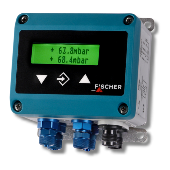
Digital 2-channel differential pressure switch/transmitter
with 4-digit color change LCD
Contents
1
2
3
4
5
6
7
8
9
10
11
12
13
14
1
Safety Instructions
1.1
General information
This operating manual contains detailed
information about the installation, opera-
tion and maintenance of the instrument.
This information must be observed and
read by the installer, operator and other skilled per-
sonnel prior to any installation and commissioning
of the instrument.
This operating manual forms part of the product and
must be kept in the immediate vicinity of the instru-
ment for easy access by the responsible personnel
at any time.
The following chapters, especially the instructions
on installation, commissioning and maintenance
contain important safety information, the non-
compliance of which may result in hazards to per-
sons, animals, environment and objects.
1.1
Personnel qualification
Only personnel trained in the installation, commis-
sioning and operation of this product may install
and operate the same.
Skilled personnel are persons who are able to judge
delegated work and possible hazards based on
their technical education, proficiency and experi-
ences, particularly due to their knowledge about the
applicable norms.
1.2
Risks of non-compliance with safety
instructions
Non-compliance with these safety instructions, in-
appropriate use of this product, and/or operation of
this product outside the limits specified for any of its
technical parameters, may result in harm to per-
sons, the environment or the system in which it is
installed.
The producer is not liable for any claims for damag-
es in such circumstances.
1.3
Safety instructions for operators
Safety instructions for the proper use of this product
must be followed. This information must be availa-
ble at all times to personnel responsible for installa-
tion, operation, maintenance and inspection of this
product.
Adequate steps must be taken to prevent the occur-
rence of hazardous conditions that can be caused
by electric energy and the convertible energy of the
process media and/or improper connec-
tion of the instrument. Detailed infor-
mation can be found in the relevant na-
Advertisement
Table of Contents

Subscribe to Our Youtube Channel
Related Manuals for FISCHER DE44


Summary of Contents for FISCHER DE44
-
Page 1: Table Of Contents
Operating Manual DE44 Digital 2-channel differential pressure switch/transmitter with 4-digit color change LCD Contents Safety Instructions Intended Applications Product Description and Function Installation Commissioning and Operating Manual Maintenance Transport Service Accessories Disposal Technical data Dimensional drawings Order codes Declaration of conformity... -
Page 2: Intended Applications
Any eventual modifications/ variations will be carried out solely by • Surface technology Fischer Mess- und Regeltechnik GmbH. The device can be used as a display and switch Impermissible operational modes device and has two independent differential pres- sure inputs. -
Page 3: Installation
• The instrument must be connected electrically Installation in accordance with the relevant VDE guidelines and the guidelines of the local EVU. The device is intended for installation on level mounting plates. To screw connect to the mounting • Disconnect the system before attaching the in- plate, the device has four mounting drill holes for strument. - Page 4 You can display the individual menu points and pa- range the entry more clearly, the individual parame- rameters with the þ and ÿ buttons. ters are summarized in groups in the menu. With the û button, the respective menu point is se- Depending on the current device version (current lected or the parameters called up for change.
- Page 5 Menu (Original) Menu (Translation) Switch points Schaltpunkte Switch point 1 on Schaltpunkt 1 Ein Switch point 1 off Schaltpunkt 1 Aus Switch point 1 delay Schaltpunkt 1 Verzögerung Switch point 1 function Schaltpunkt 1 Funktion Allocation of the switch point Zuordnung des Schaltpunktes Switch point 2 on Schaltpunkt 2 Ein...
- Page 6 Funktion Function Auswahl der Funktion Selection of function Bei Funktion RADIZIERT, TABELLE: For ROOT EXTRACTED function, table: Anzahl Nachkommastellen „freie Einheit“ Number of decimal places "free unit" Messbereich Anfang „freie Einheit“ Measurement range beginning "free unit" Messbereich Ende „freie Einheit“ Measurement range end "free unit"...
- Page 7 5.4.1 Menu level switch points With Zuordnung SP (allocation SP) it can be established which input is allocated to the contacts The two switch outputs are configured by four pa- for devices with two input channels. It is possible to allocate both contacts to one channel or each rameters channel to contact.
- Page 8 The basic measurement range (see Begrenzung (limitation) parameter allows type label) cannot be changed as well limitation of the display on the range between the as the type of output signal (voltage or Messbereich Anfang (measurement range be- current). ginning) Messbereich Ende (measurement range end)
- Page 9 places are specified here. There is also the option The most important parameter is Farbe (color). of defining the unit with 4 characters. A specific background color (red, green, yellow, blue, pink, turquoise and white) can be selected TABELLE (TABLE): this function allows the free ad- here.
- Page 10 With the Hysterese (hysteresis) parameter, the correct password is entered. If the password is not quick and unwanted change of color can be pre- active, the display immediately jumps to the menu. vented. The hysteresis can be set in a range of 0.1...
-
Page 11: Maintenance
Maintenance Service The device does not require maintenance. All defective or faulty devices are to be sent directly to our repair department. We would like to ask you to coordinate all device returns with our sales de- In order to ensure reliable operation and a long ser- vice life of the device we recommend regular check- partment. -
Page 12: Technical Data
11 Technical data 40 60 100 ±2.5 ±4 ±6 ±10 ±16 ±25 ±40 ±60 ±100 mbar Basic measurement range 400 600 1000 1600 ±250 10 ±0.25 ±0.4 ±0.6 ±1 ±1.6 ±2.5 ±4 ±6 Max. stat. operating pressure mbar Burst pressure 1500 1500 mbar... -
Page 13: Dimensional Drawings
12 Dimensional drawings Plug 1 Plug 2 Back view Without wall mounting plate Wall mounting plate (optional) (Standard design) 70.5 61.5 Drill holes for Hose screw connection M12 plug connection plate screws Ø 3.5 Wiring diagram Plug 1 Plug 2 Programming With film keypad with menu-guided operation;... -
Page 14: Order Codes
13 Order codes Digital 2-channel differential pressure switch/transmitter with 4 digit color change LCD DE44 Channel 1 - measurement range auth. stat. operating pressure … mbar ....50 mbar ....... > … mbar ....50 mbar ....... >... -
Page 15: Declaration Of Conformity
14 Declaration of conformity Page 15... - Page 16 Technische Änderungen vorbehalten • Subject to change without notice • Changements techniques sous réserve Fischer Mess- und Regeltechnik GmbH • Bielefelder Str. 37a • D-32107 Bad Salzuflen • Tel. +49 5222 9740 • Fax +49 5222 7170 • eMail: info@fischermesstechnik.de • www.fischermesstechnik.de...
Need help?
Do you have a question about the DE44 and is the answer not in the manual?
Questions and answers