
Related Manuals for FISCHER DA01 VUW


Summary of Contents for FISCHER DA01 VUW
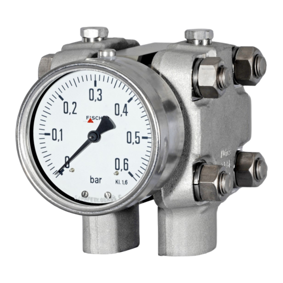
- Page 1 Operating manual DA01 VUW Differential pressure measuring device Pressure levels PN250/PN400 Standard version...
- Page 2 Great care was taken when compiling the texts and illustrations; nevertheless, errors cannot be ruled out. The company FISCHER Mess- und Regeltechnik GmbH will not accept any legal responsibility or liability for this.
-
Page 3: Table Of Contents
FISCHER Mess- und Regeltechnik GmbH Table of Contents Table of Contents 1 Sicherheitshinweise ............................ 4 1.1 General .............................. 4 1.2 Personnel Qualification.......................... 4 1.3 Risks due to Non-Observance of Safety Instructions ................ 4 1.4 Safety Instructions for the Operating Company and the Operator............ 4 1.5 Unauthorised Modification ........................ 4 1.6 Inadmissible Modes of Operation ...................... 4... -
Page 4: Sicherheitshinweise
1 | Sicherheitshinweise FISCHER Mess- und Regeltechnik GmbH 1 Sicherheitshinweise 1.1 General WARNING This operating manual contains instructions fundamental to the installation, op- eration and maintenance of the device that must be observed unconditionally. It must be read by the assembler, operator and the specialized personnel in charge of the instrument before it is installed and put into operation. -
Page 5: Safe Working Practices For Maintenance And Installation Work
FISCHER Mess- und Regeltechnik GmbH Sicherheitshinweise | 1 1.7 Safe working practices for maintenance and installation work The safety instructions given in this operating manual, any nationally applicable regulations on accident prevention and any of the operating company's internal work, operating and safety guidelines must be observed. -
Page 6: Product And Functional Description
2 | Product and functional description FISCHER Mess- und Regeltechnik GmbH 2 Product and functional description 2.1 Delivery scope • Differential pressure measuring device DA01 • Operating Manual 2.2 Equipment versions The following illustrations depict typical combinations of the measuring cell, measured value display and contact elements. - Page 7 FISCHER Mess- und Regeltechnik GmbH Product and functional description | 2 2.2.2 Nameplate 2.2.3 Contact elements Limit switch in accordance with Rotation angle encoder in accordance data sheet KE## with data sheet KE09 for standard devices Low-action contacts KINAX 3W2 708-226D0...
- Page 8 2 | Product and functional description FISCHER Mess- und Regeltechnik GmbH 2.2.5 Assembly Wall mounting Pipe mounting Panel mounting set type 1 Panel mounting set type 2 with panel mounting set with front ring Fig. 5: Assembly The panel installation fittings can only be used in devices with a small measur- ing cell (Ø75) and a display in the NG100 bayonet ring casing.
- Page 9 FISCHER Mess- und Regeltechnik GmbH Product and functional description | 2 Small measuring cell Ø75 Measuring range 0 ... 0.6 bar 0 ... 1 bar 0 ... 1.6 bar 0 ... 2.5 bar 0 ... 4.0 bar 0 ... 6bar 0 ...
- Page 10 2 | Product and functional description FISCHER Mess- und Regeltechnik GmbH Large measuring cell Ø130 Measuring range 0 ... 40 mbar 0 ... 60 mbar 0 ... 100 mbar 0 ... 160 mbar 0 ... 250 mbar 0 ... 400 mbar -40 ...
-
Page 11: Function Diagram
FISCHER Mess- und Regeltechnik GmbH Product and functional description | 2 2.3 Function diagram Fig. 10: Function diagram Motion train Transfer lever Measuring shaft Pressure transfer fluid Separating membrane Connecting rod Measuring diaphragm Pressure chamber 2.4 Design and mode of operation... -
Page 12: Assembly
3 | Assembly FISCHER Mess- und Regeltechnik GmbH 3 Assembly 3.1 General information The device can be mounted in one of the following ways (see Assembly): 1. Wall mounting The device is designed for installation onto flat assembly plates. The unit is equipped with a wall mounting plate for this mounting type. -
Page 13: Electrical Connections
FISCHER Mess- und Regeltechnik GmbH Assembly | 3 The process connections are marked with (+) and (-) symbols on the device. The pressure lines must be mounted according to these symbols. Differential pressure Higher pressure lower pressure Fig. 11: Process connection 3.3 Electrical connections... - Page 14 3 | Assembly FISCHER Mess- und Regeltechnik GmbH 3.3.2 Contact elements Contact elements are supplied in accordance with data sheet KE. This illus- trates all variants, their pin assignment and the technical data. Creep and magnetic spring contacts The terminal numbers always correspond to the contact number an are as- signed to the target indicators from left to right.
-
Page 15: Commissioning
FISCHER Mess- und Regeltechnik GmbH Commissioning | 4 4 Commissioning 4.1 General All electrical supply, operating and measuring lines, and the pressure connec- tions must have been correctly installed before commissioning. All supply lines are arranged so that there are no mechanical forces acting on the device. -
Page 16: Zero Point Correction
4 | Commissioning FISCHER Mess- und Regeltechnik GmbH 4.3 Zero point correction The differential pressure measuring units are set in the factory before delivery so that they do not usually need to be adjusted at the assembly site. If this is still necessary, proceed as follows: •... -
Page 17: Servicing
FISCHER Mess- und Regeltechnik GmbH Servicing | 5 5 Servicing 5.1 Maintenance The instrument is maintenance-free. We recommend the following regular in- spection to guarantee reliable operation and a long service life: • Check the function in combination with downstream components. -
Page 18: Technical Data
6 | Technical Data FISCHER Mess- und Regeltechnik GmbH 6 Technical Data 6.1 Allgemeines EXECUTION Nominal Measuring Application information pressure cell DA01 V … PN250 Ø75 Measuring ranges: 0…0.6 bar to 0…25 bar Remote seals: It is possible to attach remote seals for all measuring ranges. The re- mote seals need to be designed for the displacement volume, the length of the cable and the application temperature. -
Page 19: Input Variables
FISCHER Mess- und Regeltechnik GmbH Technical Data | 6 6.2 Input variables Measuring variable Differential pressure in gaseous and fluid aggressive media. General Rated pressure of the measuring Max. static operating pressure system Durability One-sided over-pressure-proof up to the rated pressure of the measuring system... -
Page 20: Construction Design
6 | Technical Data FISCHER Mess- und Regeltechnik GmbH 6.4 Construction design Materials Measured value display Material Material no. AISI Bayonet ring housing NG100, NG160 CrNi steel 1.4301 Process connection (all models) CrNi steel 1.4404 316L ® Intermediate plate AlMgSiPb... - Page 21 FISCHER Mess- und Regeltechnik GmbH Technical Data | 6 6.4.1 Additional Attachments 6.4.1.1 Contact elements Limit signal transmitters (contacts) and capacitive rotation angle transducers with an output signal proportional to the angular position can be fitted into a housing augmented by a corresponding bayonet ring connector.
- Page 22 6 | Technical Data FISCHER Mess- und Regeltechnik GmbH 6.4.2 Electrical connection In the case of devices with additional electronic equipment, the connection is realised using a cable socket attached to the side and/or with a Han 7D con- nector on th epower plant models. The pin assignment depends on the ordered mode and is stated in the data sheet KE or KE09.
- Page 23 FISCHER Mess- und Regeltechnik GmbH Technical Data | 6 6.4.3 Dimensional drawings All dimensions in mm unless otherwise stated Small measuring system (Ø75) (with installed contacts) (with installed contacts) Cable socket Flange based on DIN EN 61518 Wall mounting plate G½...
- Page 24 6 | Technical Data FISCHER Mess- und Regeltechnik GmbH Large measuring system (Ø130) 277.5 (with installed contacts) 229.5 (with installed contacts) Cable socket Wall mounting plate Flange based on DIN EN 61518 G½ 54.4 7/16 UNF Fig. 24: Dimensional drawing (Large measuring system Ø130) Installation of front panel type 1 (only small measuring system Ø75 and NG100 display)
- Page 25 FISCHER Mess- und Regeltechnik GmbH Technical Data | 6 Installation of front panel type 2 The front plate thickness must be min. 2 mm. Front ring Bayonet ring with connecting bracket NG100 A suitable steel construction must be used to ensure NG160 that the front plate can bear the weight of the DA03.
- Page 26 6 | Technical Data FISCHER Mess- und Regeltechnik GmbH Contact elements NG100 = 90 NG100 = 138 NG160 = 120 NG160 = 167.5 Fig. 27: Dimensional drawing contact devices Shut-off fitting Cutting ring connection G3/8 with inner spindle thread for 12 mm pipe...
-
Page 27: Order Codes
FISCHER Mess- und Regeltechnik GmbH Order Codes | 7 7 Order Codes Code no. 15 16 Type Device model: Pressure level Measuring cell PN250 Ø75 PN400 Ø75 PN250 Ø130 Measuring range: Small measuring system [2.3] Measuring range Device model Ø75 0 …... - Page 28 7 | Order Codes FISCHER Mess- und Regeltechnik GmbH Large measuring system [2.3] Measuring range Device model Ø130 0 … 40 mbar ● 0 … 60 mbar ● 0 … 100 mbar ● 0 … 160 mbar ● 0 … 250 mbar ●...
-
Page 29: Accessories
FISCHER Mess- und Regeltechnik GmbH Order Codes | 7 Fluid filling: Without fluid filling Glycerine Paraffin oil Silicon oil Special functions: [10] Without special function Adjustable marker needle Resettable drag needle Contacts/transmitters: [11] No contacts/transmitters Built-in contacts as per data sheet KE... -
Page 30: Eu Declarations Of Conformity
8 | EU Declarations of conformity FISCHER Mess- und Regeltechnik GmbH 8 EU Declarations of conformity Fig. 29: CE_EN_DA01_10 30 / 32 BA_EN_DA01_VUW... - Page 31 FISCHER Mess- und Regeltechnik GmbH EU Declarations of conformity | 8 Fig. 30: CE_EN_DA01_20 BA_EN_DA01_VUW 31 / 32...
-
Page 32: Eac Declaration
9 | EAC Declaration FISCHER Mess- und Regeltechnik GmbH 9 EAC Declaration Fig. 31: ЕАЭС N RU Д-DЕ.АЛ16.В.77754 32 / 32 BA_EN_DA01_VUW...
Need help?
Do you have a question about the DA01 VUW and is the answer not in the manual?
Questions and answers