
Related Manuals for FISCHER DA01 0A Series


Summary of Contents for FISCHER DA01 0A Series
- Page 1 Operating manual DA01 VUW (ATEX) Differential pressure measuring device Pressure levels PN250/PN400 Models for use in explosive areas DA01 ... 0A DA01 ... 1B DA01 ... 1C DA01 ... 2D...
- Page 2 Great care was taken when compiling the texts and illustrations; Nevertheless, errors cannot be ruled out. The company FISCHER Mess- und Regeltechnik GmbH will not accept any legal responsibility or liability for this.
-
Page 3: Table Of Contents
FISCHER Mess- und Regeltechnik GmbH Table of Contents Table of Contents 1 Sicherheitshinweise ............................ 4 1.1 General .............................. 4 1.2 Personnel Qualification.......................... 4 1.3 Risks due to Non-Observance of Safety Instructions ................ 4 1.4 Safety Instructions for the Operating Company and the Operator............ 4 1.5 Unauthorised Modification ........................ 5 1.6 Inadmissible Modes of Operation ...................... 5... -
Page 4: Sicherheitshinweise
1 | Sicherheitshinweise FISCHER Mess- und Regeltechnik GmbH 1 Sicherheitshinweise 1.1 General This operating manual contains basic instructions for the installation, operation and maintenance of the device that must be followed without fail. It must be read by the installer, the operator and the responsible specialist personnel be- fore installing and commissioning the device. -
Page 5: Unauthorised Modification
FISCHER Mess- und Regeltechnik GmbH Sicherheitshinweise | 1 The instrument must be decommissioned and secured against inadvertent re- operation if a situation arises in which it must be assumed that safe operation is no longer possible. Reasons for this assumption could be: •... -
Page 6: Pictogram Explanation
1 | Sicherheitshinweise FISCHER Mess- und Regeltechnik GmbH 1.8 Pictogram explanation DANGER Type and source of danger This indicates a direct dangerous situation that could lead to death or serious injury (highest danger level). a) Avoid danger by observing the valid safety regulations. -
Page 7: Product And Functional Description
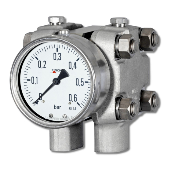
FISCHER Mess- und Regeltechnik GmbH Product and functional description | 2 2 Product and functional description 2.1 Delivery scope • Differential pressure measuring device DA01 • Operating Manual 2.2 Equipment versions The following illustrations depict typical combinations of the measuring cell, measured value display and contact elements. - Page 8 2 | Product and functional description FISCHER Mess- und Regeltechnik GmbH 2.2.2 Nameplate Order code Article no. DA01V06R03LW001B Contact function NO contact Measuring range 0 ... 6 bar p stat. max. 250 bar Prod. no. 2106759.01.257 Made in Germany Connection diagram...
- Page 9 FISCHER Mess- und Regeltechnik GmbH Product and functional description | 2 2.2.5 Assembly Wall mounting Pipe mounting Panel mounting set type 1 Panel mounting set type 2 with panel mounting set with front ring Fig. 6: Assembly The panel installation fittings can only be used in devices with a small measur- ing cell (Ø75) and a display in the NG100 bayonet ring casing.
- Page 10 2 | Product and functional description FISCHER Mess- und Regeltechnik GmbH 2.2.6 Equipment features (overview) In the following, the equipment options of the DA01 are shown depending on the measuring cell used and the pressure stage. Legend available on request Small measuring cell Ø75...
- Page 11 FISCHER Mess- und Regeltechnik GmbH Product and functional description | 2 Large measuring cell Ø130 Measuring range 0 ... 40 mbar 0 ... 60 mbar 0 ... 100 mbar 0 ... 160 mbar 0 ... 250 mbar 0 ... 400 mbar Fig. 9: Große Messzelle Ø130 Messwertanzeige Ø100...
-
Page 12: Function Diagram
2 | Product and functional description FISCHER Mess- und Regeltechnik GmbH 2.3 Function diagram Fig. 11: Function diagram Motion train Transfer lever Measuring shaft Pressure transfer fluid Separating membrane Connecting rod Measuring diaphragm Pressure chamber 2.4 Design and mode of operation... -
Page 13: Assembly
FISCHER Mess- und Regeltechnik GmbH Assembly | 3 3 Assembly 3.1 General information The device can be mounted in one of the following ways (see Assembly): 1. Wall mounting The device is designed for installation onto flat assembly plates. The unit is equipped with a wall mounting plate for this mounting type. -
Page 14: Electrical Connections
3 | Assembly FISCHER Mess- und Regeltechnik GmbH 3.3 Electrical connections DANGER Operation in areas at risk of explosion If operated in explosive areas, the electrical data of the unit and the valid local regulations and guidelines for the installation and operation of electrical systems in explosive areas must be observed. - Page 15 FISCHER Mess- und Regeltechnik GmbH Assembly | 3 Fig. 15: HAN connector Cable screw connection M20 x 1.5 2 Sleeve housing Han 3A Socket insert Han 7D 4 Pin insert Han 7D Safety clip 6 Attachment casing Han 3D 3.3.2 Contact elements...
-
Page 16: Use In Areas At Risk Of Explosion
3 | Assembly FISCHER Mess- und Regeltechnik GmbH 3.4 Use in areas at risk of explosion 3.4.1 Differential pressure transmitter without contact element DA01 … 0A II 2G Ex h IIC T4 Gb II 2D Ex h IIIC T95°C Db Explosive areas Zone 1 and 2, and 21 and 22, risk from gases and dry dust. - Page 17 FISCHER Mess- und Regeltechnik GmbH Assembly | 3 3.4.2 Differential pressure transmitter with magnetic spring contacts DA01 … 1B II 2G Ex h IIC T4 Gb Simple electric operating equipment acc. to EN60079-11 sec: 5.7 in explosive areas Zone 1 and 2.
- Page 18 3 | Assembly FISCHER Mess- und Regeltechnik GmbH 3.4.3 Differential pressure transmitter with inductive contacts DA01 … 1C II 2G Ex h IIC T4 Gb II 2D Ex h IIIC T95°C Db Explosive areas Zone 1 and 2, and 21 and 22, risk from gases and dry dust.
- Page 19 FISCHER Mess- und Regeltechnik GmbH Assembly | 3 3.4.4 Differential pressure transmitter with rotation angle transducer DA01 … 2D II 2G Ex h IIC T4 Gb Explosive areas Zone 1 and 2, risk from gases. Rotation angle transducer: KE0905#9 Allowed temperatures: •...
-
Page 20: Commissioning
4 | Commissioning FISCHER Mess- und Regeltechnik GmbH 4 Commissioning 4.1 General All electrical supply, operating and measuring lines, and the pressure connec- tions must have been correctly installed before commissioning. All supply lines are arranged so that there are no mechanical forces acting on the device. -
Page 21: Switch Point Setting
FISCHER Mess- und Regeltechnik GmbH Commissioning | 4 • Remove the closing screw The zero point correction screw is located be- hind. • Set the measurement value pointer to the scale zero point using the zero point correction screw. • Mount the closing screw Closing screw 1.2 x 7... -
Page 22: Servicing
5 | Servicing FISCHER Mess- und Regeltechnik GmbH 5 Servicing 5.1 Maintenance The instrument is maintenance-free. We recommend the following regular in- spection to guarantee reliable operation and a long service life: • Check the function in combination with downstream components. -
Page 23: Technical Data
FISCHER Mess- und Regeltechnik GmbH Technical Data | 6 6 Technical Data 6.1 Allgemeines EXECUTION Nominal Measuring Application information pressure cell DA01 V … PN250 Ø75 Measuring ranges: 0…0.6 bar to 0…25 bar Remote seals: It is possible to attach remote seals for all measuring ranges. The re- mote seals need to be designed for the displacement volume, the length of the cable and the application temperature. -
Page 24: Input Variables
6 | Technical Data FISCHER Mess- und Regeltechnik GmbH 6.2 Input variables Measuring variable Differential pressure in gaseous and fluid aggressive media. General Rated pressure of the measuring Max. static operating pressure system Durability One-sided over-pressure-proof up to the rated pressure of the measuring system... -
Page 25: Construction Design
FISCHER Mess- und Regeltechnik GmbH Technical Data | 6 6.4 Construction design Materials Measured value display Material Material no. AISI Bayonet ring housing NG100, NG160 CrNi steel 1.4301 Process connection (all models) CrNi steel 1.4404 316L ® Intermediate plate AlMgSiPb... - Page 26 6 | Technical Data FISCHER Mess- und Regeltechnik GmbH 6.4.1.2 Fluid charging Under aggravated operating conditions, such as vibrations and extreme pres- sure fluctuations, or in order to avoid condensation forming if used outdoors, the casing can be filled with the following fluids depending in the type of contacts in-...
- Page 27 FISCHER Mess- und Regeltechnik GmbH Technical Data | 6 6.4.2 Electrical connection In the case of devices with additional electronic equipment, the connection is realised using a cable socket attached to the side and/or with a Han 7D con- nector on th epower plant models. The pin assignment depends on the ordered mode and is stated in the data sheet KE or KE09.
- Page 28 6 | Technical Data FISCHER Mess- und Regeltechnik GmbH 6.4.3 Dimensional drawings All dimensions in mm unless otherwise stated Small measuring system (Ø75) (with installed contacts) (with installed contacts) Cable socket Flange based on DIN EN 61518 Wall mounting plate G½...
- Page 29 FISCHER Mess- und Regeltechnik GmbH Technical Data | 6 Large measuring system (Ø130) 277.5 (with installed contacts) 229.5 (with installed contacts) Cable socket Wall mounting plate Flange based on DIN EN 61518 G½ 54.4 7/16 UNF Fig. 26: Dimensional drawing (Large measuring system Ø130) Installation of front panel type 1 (only small measuring system Ø75 and NG100 display)
- Page 30 6 | Technical Data FISCHER Mess- und Regeltechnik GmbH Installation of front panel type 2 The front plate thickness must be min. 2 mm. Front ring Bayonet ring with connecting bracket NG100 A suitable steel construction must be used to ensure NG160 that the front plate can bear the weight of the DA03.
- Page 31 FISCHER Mess- und Regeltechnik GmbH Technical Data | 6 Contact elements NG100 = 90 NG100 = 138 NG160 = 120 NG160 = 167.5 Fig. 29: Dimensional drawing contact devices Shut-off fitting Cutting ring connection G3/8 with inner spindle thread for 12 mm pipe...
-
Page 32: Order Codes
7 | Order Codes FISCHER Mess- und Regeltechnik GmbH 7 Order Codes Code no. 11 12 Type Device model: Pressure level Measuring cell PN250 Ø75 PN400 Ø75 PN250 Ø130 Measuring range: Small measuring system [2.3] Measuring range Device model Ø75 0 …... - Page 33 FISCHER Mess- und Regeltechnik GmbH Order Codes | 7 Design of the measuring system: Pressure chamber CrNi steel 1.4404 (AISI 316L) Measuring membrane standard Pressure chamber CrNi steel 1.4404 (AISI 316L) Measuring membrane Hastelloy C276 Process connection: [5.6] Flange connection based on DIN EN 61518 with internal thread G½...
-
Page 34: Accessories
7 | Order Codes FISCHER Mess- und Regeltechnik GmbH Contacts/transmitters/ATEX: [11.12] ATEX model Non-electrical unit II 2G Ex h IIC T4 Gb (without switch contacts) II 2D Ex h IIICT95°C Db Unit with magnetic spring contacts II 2G Ex h IIC T4 Gb KE##M##0B4H2 Simple electrical operating equipment acc. -
Page 35: Eu Declarations Of Conformity
FISCHER Mess- und Regeltechnik GmbH EU Declarations of conformity | 8 8 EU Declarations of conformity Fig. 31: CE_EN_DA01_0A BA_EN_DA01_VUW_ATEX 35 / 44... - Page 36 8 | EU Declarations of conformity FISCHER Mess- und Regeltechnik GmbH Fig. 32: CE_EN_DA01_1B Part1 36 / 44 BA_EN_DA01_VUW_ATEX...
- Page 37 FISCHER Mess- und Regeltechnik GmbH EU Declarations of conformity | 8 Fig. 33: CE_EN_DA01_1B Part2 BA_EN_DA01_VUW_ATEX 37 / 44...
- Page 38 8 | EU Declarations of conformity FISCHER Mess- und Regeltechnik GmbH Fig. 34: CE_EN_DA01_1C 38 / 44 BA_EN_DA01_VUW_ATEX...
- Page 39 FISCHER Mess- und Regeltechnik GmbH EU Declarations of conformity | 8 Fig. 35: CE_EN_DA01_2D Part1 BA_EN_DA01_VUW_ATEX 39 / 44...
- Page 40 8 | EU Declarations of conformity FISCHER Mess- und Regeltechnik GmbH Fig. 36: CE_EN_DA01_2D Part2 40 / 44 BA_EN_DA01_VUW_ATEX...
-
Page 41: Eac Declaration
FISCHER Mess- und Regeltechnik GmbH EAC Declaration | 9 9 EAC Declaration Fig. 37: ЕАЭС N RU Д-DЕ.АЛ16.В.77754 BA_EN_DA01_VUW_ATEX 41 / 44... - Page 42 9 | EAC Declaration FISCHER Mess- und Regeltechnik GmbH 42 / 44 BA_EN_DA01_VUW_ATEX...
- Page 43 FISCHER Mess- und Regeltechnik GmbH EAC Declaration | 9 BA_EN_DA01_VUW_ATEX 43 / 44...
- Page 44 9 | EAC Declaration FISCHER Mess- und Regeltechnik GmbH 44 / 44 BA_EN_DA01_VUW_ATEX...
Need help?
Do you have a question about the DA01 0A Series and is the answer not in the manual?
Questions and answers