
Related Manuals for FISCHER DA09


Summary of Contents for FISCHER DA09
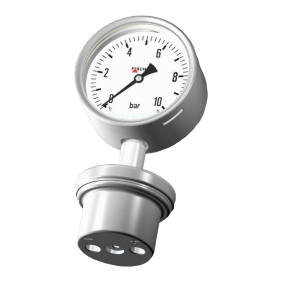
- Page 1 Operating manual DA09 Differential pressure measuring unit Pressure levels PN10/PN25 Diaphragm manometer CrNi-steel model...
- Page 2 Great care was taken when compiling the texts and illustrations; Nevertheless, errors cannot be ruled out. The company FISCHER Mess- und Regeltechnik GmbH will not accept any legal responsibility or liability for this.
-
Page 3: Table Of Contents
FISCHER Mess- und Regeltechnik GmbH Table of Contents Table of Contents 1 Safety information ......................4 1.1 General........................... 1.2 Personnel Qualification......................1.3 Risks due to Non-Observance of Safety Instructions ............. 1.4 Safety Instructions for the Operating Company and the Operator ......... -
Page 4: Safety Information
1 | Safety information FISCHER Mess- und Regeltechnik GmbH 1 Safety information 1.1 General This operating manual contains basic instructions for the installation, operation and maintenance of the device that must be followed without fail. It must be read by the installer, the operator and the responsible specialist personnel be- fore installing and commissioning the device. -
Page 5: Inadmissible Modes Of Operation
FISCHER Mess- und Regeltechnik GmbH Safety information | 1 1.6 Inadmissible Modes of Operation The operational safety of this instrument can only be guaranteed if it is used as intended. The instrument model must be suitable for the medium used in the system. -
Page 6: Product And Functional Description
(see Techn. data). The DA09 can be delivered with a contact element. If the set limit values are ex- ceeded, the output power circuits are opened or closed, and/or a 0/4…20 mA output signal proportional to the displayed value is issued for a capacitive rota- tion angle encoder. -
Page 7: Equipment Versions
FISCHER Mess- und Regeltechnik GmbH Product and functional description | 2 2.5 Equipment versions The illustrations are just examples. The equipment features can be combined according to the order code. Bayonet ring casing NG160 Bayonet ring casing NG100 bar measuring system... -
Page 8: Nameplate
2 | Product and functional description FISCHER Mess- und Regeltechnik GmbH 2.6 Nameplate This type plate serves as an example of the information that is stated. The data shown is purely fictive, but does correspond to the actual conditions. For more information, please see the order code at the end of these instructions. -
Page 9: Assembly
FISCHER Mess- und Regeltechnik GmbH Assembly | 3 3 Assembly 3.1 General The device can be mounted in one of the following ways: 1. Direct assembly The unit is suitable for direct assembly to pressure lines. The unit weight de- pends on the design. -
Page 10: Electrical Connections
3 | Assembly FISCHER Mess- und Regeltechnik GmbH Differential pressure Higher pressure lower pressure The following options are available for the process connection: G½ G½ G½ G½ Inner thread Outer thread Cutting ring- screw connection 1/4-18 NPT 1/4-18 NPT G½... - Page 11 FISCHER Mess- und Regeltechnik GmbH Assembly | 3 Fig. 8: HAN 7D Cable screw connection M20 x 1.5 Sleeve housing Han 3A Socket insert Han 7D Pin insert Han 7D Safety clip Attachment casing Han 3D 3.3.2 Contact elements Contact elements are supplied in accordance with data sheet KE. This illus- trates all variants, their pin assignment and the technical data.
-
Page 12: Commissioning
4 | Commissioning FISCHER Mess- und Regeltechnik GmbH 4 Commissioning 4.1 General All electrical supply, operating and measuring lines, and the pressure connec- tions must have been correctly installed before commissioning. All supply lines are arranged so that there are no mechanical forces acting on the device. -
Page 13: Switch Point Setting
FISCHER Mess- und Regeltechnik GmbH Commissioning | 4 4.3 Switch point setting There is an adjustment lock attached to the front pane of the measuring unit on units with contact elements. This means that the contacts attached to the target indicators can be set to any point along the scale. -
Page 14: Servicing
5 | Servicing FISCHER Mess- und Regeltechnik GmbH 5 Servicing 5.1 Maintenance The instrument is maintenance-free. We recommend the following regular in- spection to guarantee reliable operation and a long service life: • Check the function in combination with downstream components. -
Page 15: Technical Data
FISCHER Mess- und Regeltechnik GmbH Technical Data | 6 6 Technical Data 6.1 General Please also observe the order code here. 6.2 Input variables Measuring variable Absolute pressure for gaseous, fluid and aggressive media. Measuring ranges [bar, mbar] Measuring range Measuring range 0 …... -
Page 16: Measurement Accuracy
6 | Technical Data FISCHER Mess- und Regeltechnik GmbH Pressure load Idle load Scale upper value Alternating load Scale upper value Overload capability on one side (+) and 10 x Scale upper value ≤ PN 6.3 Measurement accuracy Accuracy class Characteristic curve deviation ±... - Page 17 FISCHER Mess- und Regeltechnik GmbH Technical Data | 6 Electrical connection In the case of devices with additional electronic equipment, the connection is realised using a cable socket attached to the side and/or with a Han 7D con- nector on the power plant models. The pin assignment depends on the ordered mode and is stated in the data sheet KE or KE09.
- Page 18 6 | Technical Data FISCHER Mess- und Regeltechnik GmbH Additional Attachments Contact elements Limit signal transmitters (contacts) and capacitive rotation angle transducers with an output signal proportional to the angular position can be fitted into a housing augmented by a corresponding bayonet ring connector.
- Page 19 FISCHER Mess- und Regeltechnik GmbH Technical Data | 6 6.6 Dimensional drawings All dimensions in mm unless otherwise stated 6.6.1 Standard version 40.5 Ø63 Fig. 17: Dimensional picture 25 ... 250 mbar Measuring range 25…250 mbar Housing Tol. NG100 ± 0.1 15.5...
- Page 20 6 | Technical Data FISCHER Mess- und Regeltechnik GmbH 6.6.2 Tube and wall mounting The dimensions stated apply for all housing models. The example shown is a bayonet ring housing NG160. Ø62 2'' tube 73 ± 0.1 Tube assembly Measuring range Tol.
- Page 21 FISCHER Mess- und Regeltechnik GmbH Technical Data | 6 6.6.3 Process connection 25 ... 250 mbar 0.4 ... 25 bar G¼ Fig. 19: Process connection 6.6.3.1 Connection port with cylindrical external thread G¼ Tol. ±0.1 ±0.2 ±0.3 ±0.2 ±0.2 ±0.1 ±0.1 G½...
- Page 22 6 | Technical Data FISCHER Mess- und Regeltechnik GmbH 6.6.4 Additional Attachments 6.6.4.1 Safety model The device can be supplied in a safety housing acc. to DIN 837 with an un- breakable partition wall and a rear wall that can be blown out (S3).
- Page 23 FISCHER Mess- und Regeltechnik GmbH Technical Data | 6 Model with HAN 7D (power plant) NG100 = 138 NG160 = 167.5 Fig. 25: Bayonet ring housing with HAN 7D BA_EN_DA09_EG 23/32...
-
Page 24: Order Codes
7 | Order Codes FISCHER Mess- und Regeltechnik GmbH 7 Order Codes Code no. 10 11 12 13 14 15 16 Type [1.2] Measuring [1.2] Measuring range range 0 … 0.6 bar 25 bar -1 … 0.6 bar 25 bar 0 …... - Page 25 FISCHER Mess- und Regeltechnik GmbH Order Codes | 7 Nominal pressure (PN) 10 bar = 1 MPa ≈ 145 PSI MB ≤ 250 mbar = 25 kPa ≈ 3.63 PSI 25 bar = 2.5 MPa ≈ 362 PSI MB ≥ 400 mbar = 40 kPa ≈ 5.80 PSI The rated pressure ranges (PN) are linked to the measuring ranges (MB) and cannot be freely combined.
-
Page 26: Accessories
7 | Order Codes FISCHER Mess- und Regeltechnik GmbH [15] Contacts/transmitters No contacts/transmitters Contacts as per data sheet KE Measuring range ≥ 100 mbar Rotation angle encoder in accordance Measuring range ≥ 100 mbar with data sheet KE09 Contacts with socket Power plant model 7.1 Accessories... -
Page 27: Attachments
FISCHER Mess- und Regeltechnik GmbH Attachments | 8 8 Attachments 8.1 EU declarations of conformity Fig. 26: CE_EN_DA09_10 BA_EN_DA09_EG 27/32... - Page 28 8 | Attachments FISCHER Mess- und Regeltechnik GmbH Fig. 27: CE_EN_DA09_20 28/32 BA_EN_DA09_EG...
-
Page 29: Ukca Declarations Of Conformity
FISCHER Mess- und Regeltechnik GmbH Attachments | 8 8.2 UKCA Declarations of Conformity Fig. 28: UKCA_EN_DA09_10 BA_EN_DA09_EG 29/32... - Page 30 8 | Attachments FISCHER Mess- und Regeltechnik GmbH Fig. 29: UKCA_EN_DA09_20 30/32 BA_EN_DA09_EG...
-
Page 31: Eac Declaration
FISCHER Mess- und Regeltechnik GmbH Attachments | 8 8.3 EAC Declaration Fig. 30: ЕАЭС N RU Д-DЕ.АЛ16.В.77754 BA_EN_DA09_EG 31/32... - Page 32 Mess- und Regeltechnik GmbH Bielefelder Str. 37a D-32107 Bad Salzuflen Tel. +49 5222 974-0 Fax +49 5222 7170 www.fischermesstechnik.de info@fischermesstechnik.de Technische Änderungen vorbehalten. Subject to technical changes. Sous réserve de modifications techniques.
Need help?
Do you have a question about the DA09 and is the answer not in the manual?
Questions and answers