Table of Contents
Advertisement
Quick Links
Advertisement
Table of Contents

Related Manuals for FISCHER DA12


Summary of Contents for FISCHER DA12
- Page 1 Operating manual DA12 Differential pressure - Measuring device...
- Page 2 Great care was taken when compiling the texts and illustrations; Nevertheless, errors cannot be ruled out. The company FISCHER Mess- und Regeltechnik GmbH will not accept any legal responsibility or liability for this.
-
Page 3: Table Of Contents
FISCHER Mess- und Regeltechnik GmbH Table of contents Table of contents 1 Safety instructions ......................4 1.1 General........................... 1.2 Personnel Qualification......................1.3 Risks due to Non-Observance of Safety Instructions ............. 1.4 Safety Instructions for the Operating Company and the Operator ......... -
Page 4: Safety Instructions
1 | Safety instructions FISCHER Mess- und Regeltechnik GmbH 1 Safety instructions 1.1 General This operating manual contains basic instructions for the installation, operation and maintenance of the device that must be followed without fail. It must be read by the installer, the operator and the responsible specialist personnel be- fore installing and commissioning the device. -
Page 5: Safe Working Practices For Maintenance And Installation Work
FISCHER Mess- und Regeltechnik GmbH Safety instructions | 1 1.7 Safe working practices for maintenance and installation work The safety instructions given in this operating manual, any nationally applicable regulations on accident prevention and any of the operating company's internal work, operating and safety guidelines must be observed. -
Page 6: Product And Functional Description
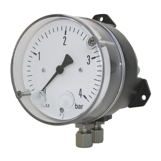
2 | Product and functional description FISCHER Mess- und Regeltechnik GmbH 2 Product and functional description 2.1 Delivery scope • Differential pressure measuring device DA12 • Operating Manual 2.2 Device versions Pressure chamber aluminium Pressure chamber stainless steel Cutting ring connection Connection shank DIN EN 837 Fig. 1: Models and options... -
Page 7: Intended Use
FISCHER Mess- und Regeltechnik GmbH Product and functional description | 2 2.3 Intended use The DA12 is a display unit for differential pressure, over-pressure and under- pressure for gas-like and fluid media. This series is ideally suited for various measuring tasks in rough environments. -
Page 8: Assembly
3 | Assembly FISCHER Mess- und Regeltechnik GmbH 3 Assembly 3.1 General information The device can be mounted in one of the following ways: 1. Wall mounting The device is designed for installation onto flat assembly plates. 2. Panel fitting The device is equipped with a special front panel set and is suitable for mounting in front panels with a wall thickness of 2 to 3 mm. - Page 9 FISCHER Mess- und Regeltechnik GmbH Assembly | 3 3.2.1 Cutting ring screw connection Counter-hold when mounting Cutting ring Union nut Precision steel tube Fig. 5: Mounting the cutting ring screw connection Preparation • Assembly is only possible with tubes that are cut off at right angles. The usual tolerances for minimum tube length, angle and chamber apply.
- Page 10 3 | Assembly FISCHER Mess- und Regeltechnik GmbH 3.2.3 Pressure hammer damping Pulsating pressure on the system side can lead to wear and functional prob- lems. To safeguard this, we recommend installing absorption elements in the pressure line. Fluid media...
-
Page 11: Start-Up
FISCHER Mess- und Regeltechnik GmbH Start-up | 4 4 Start-up 4.1 General All pressure lines must have been correctly installed before commissioning. All connections are arranged so that there are no mechanical forces acting on the device. CAUTION Leak test The pressure lines need to be checked for leaks before commissioning. -
Page 12: Servicing
5 | Servicing FISCHER Mess- und Regeltechnik GmbH 5 Servicing 5.1 Maintenance The instrument is maintenance-free. We recommend the following regular in- spection to guarantee reliable operation and a long service life: • Check the function in combination with downstream components. -
Page 13: Technical Data
FISCHER Mess- und Regeltechnik GmbH Technical data | 6 6 Technical data 6.1 General Information Reference conditions (acc. to IEC 61298-1) Temperature +15 … +25 °C Relative humidity 45 … 75 % Air pressure 86 … 106 kPa 860 … 1060 mbar... -
Page 14: Construction Design
6 | Technical data FISCHER Mess- und Regeltechnik GmbH 6.4 Construction design Process connection Inner thread G 1/4 Brass, CrNi steel Connection shank G¼ B DIN EN 837 Brass, CrNi steel, Cutting ring connection in brass for 6 mm galvanised steel... - Page 15 FISCHER Mess- und Regeltechnik GmbH Technical data | 6 6.4.2 Dimensional drawings All dimensions in mm unless otherwise stated The following are the dimensional diagrams for the pressure chambers in alu- minium. The dimensional diagrams for the pressure chambers in stainless steel are similar.
- Page 16 6 | Technical data FISCHER Mess- und Regeltechnik GmbH Process connection variants G¼B Ø21 Internal thread G¼B G¼B G¼B Tube diameter Connection fitting Cutting ring- according to DIN 837 screw connection Fig. 10: Process connection Connecting shanks Cutting ring screw connection...
-
Page 17: Order Codes
FISCHER Mess- und Regeltechnik GmbH Order Codes | 7 7 Order Codes Code no. Type Measuring diaphragm [1.2] Measuring range NBR / VITON Inconel 718 0 to 250 mbar 0 to 400 mbar 0 to 0.6 bar 0 to 1 bar 0 to 1.6 bar... - Page 18 DZ11 Installation set for retrofitting from wall mounting to switch panel in- stallation. Please state the precise device type of the DA12 because there are different switch panel installtion sets depending on the model. DZ23/24 The shut-off valve DZ23 with three spindles and DZ24 with four spindles can be of a decisive benefit when mounting the differential pressure measuring device DA12.
- Page 19 FISCHER Mess- und Regeltechnik GmbH Notes BA_EN_DA12 19/20...
- Page 20 Mess- und Regeltechnik GmbH Bielefelder Str. 37a D-32107 Bad Salzuflen Tel. +49 5222 974-0 Fax +49 5222 7170 www.fischermesstechnik.de info@fischermesstechnik.de Technische Änderungen vorbehalten. Subject to technical changes. Sous réserve de modifications techniques.
Need help?
Do you have a question about the DA12 and is the answer not in the manual?
Questions and answers