
Related Manuals for FISCHER DA09 series


Summary of Contents for FISCHER DA09 series
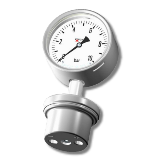
- Page 1 Operating manual DA09 (ATEX) Differential pressure measuring unit Pressure levels PN10/PN25 Diaphragm manometer for use in potentially explosive areas CrNi-steel model DA09 ... 0A DA09 ... 1B DA09 ... 1C DA09 ... 2D...
- Page 2 Great care was taken when compiling the texts and illustrations; Nevertheless, errors cannot be ruled out. The company FISCHER Mess- und Regeltechnik GmbH will not accept any legal responsibility or liability for this.
-
Page 3: Table Of Contents
FISCHER Mess- und Regeltechnik GmbH Table of Contents Table of Contents 1 Safety information ............................ 4 1.1 General .............................. 4 1.2 Personnel Qualification.......................... 4 1.3 Risks due to Non-Observance of Safety Instructions ................ 4 1.4 Safety Instructions for the Operating Company and the Operator............ 5 1.5 Unauthorised Modification ........................ 5... -
Page 4: Safety Information
1 | Safety information FISCHER Mess- und Regeltechnik GmbH 1 Safety information 1.1 General WARNING This operating manual contains instructions fundamental to the installation, op- eration and maintenance of the device that must be observed unconditionally. It must be read by the assembler, operator and the specialized personnel in charge of the instrument before it is installed and put into operation. -
Page 5: Safety Instructions For The Operating Company And The Operator
FISCHER Mess- und Regeltechnik GmbH Safety information | 1 1.4 Safety Instructions for the Operating Company and the Operator The safety instructions governing correct operation of the instrument must be observed. The operating company must make them available to the installation, maintenance, inspection and operating personnel. -
Page 6: Pictogram Explanation
1 | Safety information FISCHER Mess- und Regeltechnik GmbH 1.8 Pictogram explanation DANGER Type and source of danger This indicates a direct dangerous situation that could lead to death or serious injury (highest danger level). a) Avoid danger by observing the valid safety regulations. -
Page 7: Product And Functional Description
FISCHER Mess- und Regeltechnik GmbH Product and functional description | 2 2 Product and functional description 2.1 Delivery scope • Diaphragm manometer DA09 • Operating Manual 2.2 Intended use The diaphragm manometer DA09 serves to measure and display differential pressures in gaseous, fluid and aggressive media. The unit is completely made of CrNi-steel and is suitable for use in aggressive environments. -
Page 8: Design And Mode Of Operation
2 | Product and functional description FISCHER Mess- und Regeltechnik GmbH 2.4 Design and mode of operation The measuring system comprises a diaphragm and two separate pressure chambers. Differential pressure between the chambers causes axial movement of the diaphragms. A tie rod transfers this movement to an indicator. -
Page 9: Nameplate
FISCHER Mess- und Regeltechnik GmbH Product and functional description | 2 Electr. auxiliary equipment e.g. rotation angle transducer Type plate + wiring diagram Cable socket Process connection with G¼ inner thread Fig. 3: Equipment versions additional equipment 2.6 Nameplate The presented type plates serve to show an example of the information shown. -
Page 10: Assembly
3 | Assembly FISCHER Mess- und Regeltechnik GmbH 3 Assembly 3.1 General The device can be mounted in one of the following ways: 1. Direct assembly The unit is suitable for direct assembly to pressure lines. The unit weight de- pends on the design. -
Page 11: Electrical Connections
FISCHER Mess- und Regeltechnik GmbH Assembly | 3 Differential pressure Higher pressure lower pressure The following options are available for the process connection: G½ G½ G½ G½ Inner thread Outer thread Cutting ring- screw connection 1/4-18 NPT 1/4-18 NPT G½... - Page 12 3 | Assembly FISCHER Mess- und Regeltechnik GmbH 3.3.2 Cable socket M20 x 1.5 Fig. 8: Cable socket Lower part Sealing ring EPDM Middle part Sealing ring EPDM Lid screw 3.3.3 Contact elements Contact elements are supplied in accordance with data sheet KE.
-
Page 13: Use In Areas At Risk Of Explosion
FISCHER Mess- und Regeltechnik GmbH Assembly | 3 3.3.4 Rotation angle transducers KINAX 3W2 The rotation angle encoder serves to record angular positions, to prepare and provide the measured values as electrical output signals 0/4 … 20 mA for the following device. Rotation angle encoder is supplied in accordance with... - Page 14 3 | Assembly FISCHER Mess- und Regeltechnik GmbH 3.4.2 Differential pressure transmitter with magnetic spring contacts DA09 … 1B II 2G Ex h IIC T4 Gb Simple electric operating equipment acc. to EN60079-11 sec: 5.7 in explosive areas Zone 1 and 2.
- Page 15 FISCHER Mess- und Regeltechnik GmbH Assembly | 3 3.4.3 Differential pressure transmitter with inductive contacts DA09 … 1C II 2G Ex h IIC T4 Gb II 2D Ex h IIIC T95°C Db Explosive areas Zone 1 and 2, and 21 and 22, risk from gases and dry dust.
- Page 16 3 | Assembly FISCHER Mess- und Regeltechnik GmbH 3.4.4 Differential pressure transmitter with rotation angle transducer DA09 … 2D II 2G Ex h IIC T4 Gb Explosive areas Zone 1 and 2, risk from gases. Rotation angle transducer: KE0905#9 Allowed temperatures: •...
-
Page 17: Commissioning
FISCHER Mess- und Regeltechnik GmbH Commissioning | 4 4 Commissioning 4.1 General All electrical supply, operating and measuring lines, and the pressure connec- tions must have been correctly installed before commissioning. All supply lines are arranged so that there are no mechanical forces acting on the device. -
Page 18: Switch Point Setting
4 | Commissioning FISCHER Mess- und Regeltechnik GmbH 4.3 Switch point setting There is an adjustment lock attached to the front pane of the measuring unit on units with contact elements. This means that the contacts attached to the target indicators can be set to any point along the scale. -
Page 19: Servicing
FISCHER Mess- und Regeltechnik GmbH Servicing | 5 5 Servicing 5.1 Maintenance To ensure reliable operation and a long service life, we recommend carrying out the following test on a regular basis: • Check the reading. • Checking the switch function in connection with the downstream compon- ents. -
Page 20: Technical Data
6 | Technical Data FISCHER Mess- und Regeltechnik GmbH 6 Technical Data 6.1 General Please also observe the order code here. 6.2 Input variables Measuring variable Absolute pressure for gaseous, fluid and aggressive media. Measuring ranges [bar, mbar] Measuring range Measuring range 0 …... -
Page 21: Measurement Accuracy
FISCHER Mess- und Regeltechnik GmbH Technical Data | 6 Pressure load Idle load Scale upper value Alternating load Scale upper value Overload capability on one side (+) and 10 x Scale upper value ≤ PN 6.3 Measurement accuracy Accuracy class Characteristic curve deviation ±... - Page 22 6 | Technical Data FISCHER Mess- und Regeltechnik GmbH Electrical connection In the case of devices with additional electronic equipment, the connection is realised using a cable socket attached to the side. Cable socket Fig. 16: Cable socket Cable socket Number of screw terminals...
- Page 23 FISCHER Mess- und Regeltechnik GmbH Technical Data | 6 Fluid charging Under aggravated operating conditions, such as vibrations and extreme pres- sure fluctuations, or in order to avoid condensation forming if used outdoors, the casing can be filled with the following fluids depending in the type of contacts in-...
- Page 24 6 | Technical Data FISCHER Mess- und Regeltechnik GmbH 6.6 Dimensional drawings All dimensions in mm unless otherwise stated 6.6.1 Standard version 40.5 Ø63 Fig. 17: Dimensional picture 25 ... 250 mbar Measuring range 25…250 mbar Housing Tol. NG100 ± 0.1 15.5...
- Page 25 FISCHER Mess- und Regeltechnik GmbH Technical Data | 6 6.6.2 Tube and wall mounting The dimensions stated apply for all housing models. The example shown is a bayonet ring housing NG160. Ø62 2'' tube 73 ± 0.1 Tube assembly Measuring range Tol.
- Page 26 6 | Technical Data FISCHER Mess- und Regeltechnik GmbH 6.6.3 Process connection 25 ... 250 mbar 0.4 ... 25 bar G¼ Fig. 19: Process connection 6.6.3.1 Connection port with cylindrical external thread G¼ Tol. ±0.1 ±0.2 ±0.3 ±0.2 ±0.2 ±0.1 ±0.1 G½...
- Page 27 FISCHER Mess- und Regeltechnik GmbH Technical Data | 6 6.6.4 Additional Attachments 6.6.4.1 Safety model The device can be supplied in a safety housing acc. to DIN 837 with an un- breakable partition wall and a rear wall that can be blown out (S3).
-
Page 28: Order Codes
7 | Order Codes FISCHER Mess- und Regeltechnik GmbH 7 Order Codes Code no. 10 11 12 13 14 15 16 Type [1.2] Measuring [1.2] Measuring range range 0 … 0.6 bar 25 bar -1 … 0.6 bar 25 bar 0 …... - Page 29 FISCHER Mess- und Regeltechnik GmbH Order Codes | 7 [1.2] Measuring [1.2] Measuring range range 0 … 400 kPa 25 bar 0 … 600 kPa 25 bar Nominal pressure (PN) 10 bar = 1 MPa ≈ 145 PSI MB ≤ 250 mbar = 25 kPa ≈ 3.63 PSI 25 bar = 2.5 MPa ≈...
-
Page 30: Accessories
7 | Order Codes FISCHER Mess- und Regeltechnik GmbH [13] Special aspects None Increased load change resistance [15.16] ATEX Non-electrical unit II 2G Ex h IIC T4 Gb (without switch contacts) II 2D Ex h IIICT95°C Db Unit with magnetic spring contacts... -
Page 31: Attachments
FISCHER Mess- und Regeltechnik GmbH Attachments | 8 8 Attachments Fig. 25: CE_DE_DA09_0A BA_EN_DA09_EG_ATEX 31 / 40... - Page 32 8 | Attachments FISCHER Mess- und Regeltechnik GmbH Fig. 26: CE_DE_DA09_1B_Page_1 32 / 40 BA_EN_DA09_EG_ATEX...
- Page 33 FISCHER Mess- und Regeltechnik GmbH Attachments | 8 Fig. 27: CE_DE_DA09_1B_Page_2 BA_EN_DA09_EG_ATEX 33 / 40...
- Page 34 8 | Attachments FISCHER Mess- und Regeltechnik GmbH Fig. 28: CE_DE_DA09_1C_Page_1 34 / 40 BA_EN_DA09_EG_ATEX...
- Page 35 FISCHER Mess- und Regeltechnik GmbH Attachments | 8 Fig. 29: CE_DE_DA09_1C_Page_2 BA_EN_DA09_EG_ATEX 35 / 40...
- Page 36 8 | Attachments FISCHER Mess- und Regeltechnik GmbH Fig. 30: CE_DE_DA09_2D_Page_1 36 / 40 BA_EN_DA09_EG_ATEX...
- Page 37 FISCHER Mess- und Regeltechnik GmbH Attachments | 8 Fig. 31: CE_DE_DA09_2D_Page_2 BA_EN_DA09_EG_ATEX 37 / 40...
-
Page 38: Eac Declaration
8 | Attachments FISCHER Mess- und Regeltechnik GmbH 8.1 EAC Declaration Fig. 32: ЕАЭС N RU Д-DЕ.АЛ16.В.77754 38 / 40 BA_EN_DA09_EG_ATEX... - Page 39 FISCHER Mess- und Regeltechnik GmbH Attachments | 8 BA_EN_DA09_EG_ATEX 39 / 40...
- Page 40 8 | Attachments FISCHER Mess- und Regeltechnik GmbH 40 / 40 BA_EN_DA09_EG_ATEX...
Need help?
Do you have a question about the DA09 series and is the answer not in the manual?
Questions and answers