Table of Contents
Advertisement
Advertisement
Table of Contents

Related Manuals for Danfoss PLUS+1 MC0XX-1 series


Summary of Contents for Danfoss PLUS+1 MC0XX-1 series
- Page 1 Technical Information PLUS+1® MC0XX-1XX Controllers Family www.danfoss.com...
- Page 2 Added notes regarding 5.7 V and high range under Analog (AIN) specifications table; then 0201 added High Range Input Impedance for Analog Inputs chart; updated Sensor power supply ratings: Specifications (MC50-155/15B) March 2016 Updated to Engineering Tomorrow design 0102 Mar 2014 First edition L1321895 | BC00000227en-US0401 © Danfoss | April 2018...
-
Page 3: Table Of Contents
Modules housing....................................23 Product installation and start-up Connectors....................................... 24 Mounting......................................24 Machine diagnostic connector..............................25 Grounding......................................25 Hot plugging....................................25 Machine wiring guidelines................................. 25 Machine welding guidelines..............................26 ® PLUS+1 USB/CAN Gateway...............................26 L1321895 | BC00000227en-US0401 | 3 © Danfoss | April 2018... -
Page 4: Technical Information (Ti)
How to configure module input and output parameters • How to download PLUS+1 ® GUIDE applications to target PLUS+1 ® hardware modules • How to upload and download tuning parameters • ® How to use the PLUS+1 Service Tool L1321895 | BC00000227en-US0401 © Danfoss | April 2018... -
Page 5: User Liability And Safety Statements
User liability and safety statements OEM responsibility The OEM of a machine or vehicle in which Danfoss products are installed has the full responsibility for all consequences that might occur. Danfoss has no responsibility for any consequences, direct or indirect, caused by failures or malfunctions. -
Page 6: Overview
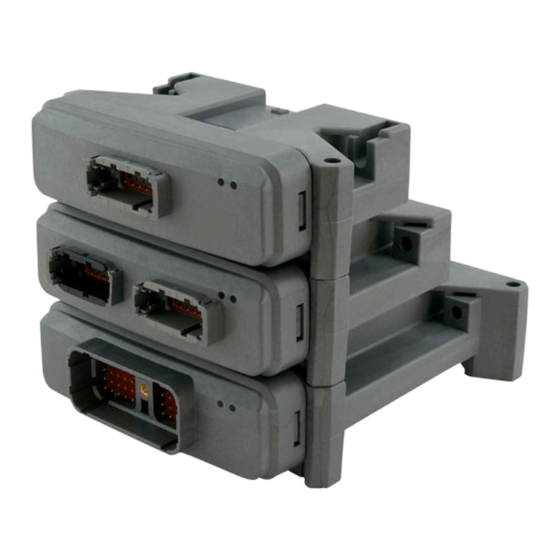
Compliant systems are incrementally expandable: additional modules can be easily added to the machine CAN bus to increase system capabilities or computational power. Three standard housings, 12, 24, and 50 pin, cover this product line. L1321895 | BC00000227en-US0401 © Danfoss | April 2018... -
Page 7: Inputs/Outputs Types And Specifications
Guaranteed low voltage. voltage Input impedance kΩ No pull up or pull down. Input impedance kΩ 13.9 14.1 14.3 Pull up to +5 V or pull down (5 V/GND) to ground. L1321895 | BC00000227en-US0401 | 7 © Danfoss | April 2018... -
Page 8: Ain
Pull to +2.5 V (2.5 V) For voltages > 5.7 V, see High range input impedance for analog inputs on page 9. In high range the input impedance decreases as the input voltage increases. L1321895 | BC00000227en-US0401 © Danfoss | April 2018... -
Page 9: High Range Input Impedance For Analog Inputs
High range input impedance for analog inputs 30000 27500 25000 22500 20000 Rxhi nopull.HiV (Vin) Rxhi pullup.HiV (Vin) 17500 Rxhi pulldn.HiV (Vin) Rxhi pullboth.HiV (Vin) 15000 12500 10000 7500 5000 Voltage L1321895 | BC00000227en-US0401 | 9 © Danfoss | April 2018... -
Page 10: A/D Refresh Rate
Rheostat inputs The following chart shows the relationship between load resistance versus worst case error over the full operating temperature -40° C to 70° C (-40° F to 158° F). L1321895 | BC00000227en-US0401 10 | © Danfoss | April 2018... -
Page 11: Din/Ain/Freqin; Din/Ain/Freqin/Rheo (All Models)
Frequency range — 5000 In steps of 1 Hz. when input is used as quad count or phase shift Low range Minimum — — 12.9 discernible voltage Maximum discernible voltage L1321895 | BC00000227en-US0401 | 11 © Danfoss | April 2018... - Page 12 Pull up to +5 V or pull down (5 V/GND) to ground. Input impedance kΩ — Pull to +2.5 V. (2.5 V) High range DAFR Input impedance kΩ — No pull up or pull down. L1321895 | BC00000227en-US0401 12 | © Danfoss | April 2018...
-
Page 13: Output Types
The module will be powered up if battery voltage is applied to the module's output pin. To protect against unintended movement, secure the machine. Caution Warranty will be voided if module is damaged. Avoid significant current driven back through an output pin. L1321895 | BC00000227en-US0401 | 13 © Danfoss | April 2018... -
Page 14: Dout And Dout/Pvgpwr
At Rload=200 Ω Output current range for a note regarding pair status bit to read OK Do not connect a digital output to battery+ (back drive) without a series diode. L1321895 | BC00000227en-US0401 14 | © Danfoss | April 2018... -
Page 15: Single Pulse Maximum Demagnetization Energy At 150 C
PVG valves can be driven with an open loop PWM. The PWM driving the control signal must be set to 0 at the same time as the digital output driving the PVE power pin is set to 0. L1321895 | BC00000227en-US0401 | 15 © Danfoss | April 2018... - Page 16 Output voltage, 100% duty Vbatt-1 cycle Output resolution of 3 A 0.25 Repeatability of full range % of full scale L1321895 | BC00000227en-US0401 16 | © Danfoss | April 2018...
- Page 17 If the instantaneous current exceeds the trip point, the driver is latched off. GUIDE application software can reset the latch and attempt to drive current again. L1321895 | BC00000227en-US0401 | 17 © Danfoss | April 2018...
-
Page 18: Controller Area Network (Can)
(using default update and 250K bus speed) Estimated module bus load (using 70 ms updates and 250K bus speed) RAM usage on MC012-XXX RAM usage on MC024-010 L1321895 | BC00000227en-US0401 18 | © Danfoss | April 2018... - Page 19 OX012-010 OX024-010 IOX012-010 IOX024-20 RAM usage on MC050-010, MC050-020 RAM usage on MC050-055 ROM usage on MC012-XXX ROM usage on MC024-010 ROM usage on MC050-010, MC050-020 ROM usage on MC050-055 L1321895 | BC00000227en-US0401 | 19 © Danfoss | April 2018...
-
Page 20: Product Ratings
Specifications (MC50-155/15B) Description Units Minimum Maximum Comment Output short circuit voltage Output voltage, sensors 4.56 5.10 Sensor power supply drops below minimum if controller power supply is less than 9 Vdc. L1321895 | BC00000227en-US0401 20 | © Danfoss | April 2018... -
Page 21: Pvg Valve Power Supply Ratings
Nominal 3.3 PVG valve power supply ratings DOUT/PVGpwr pins can provide the battery supply voltage required by Danfoss PVG valve electronics for those control strategies requiring application software control of the valve power source. When enabled, the DOUT/PVGpwr pin passes battery (reference) voltage to the PVG valve electronics. -
Page 22: Environmental Testing Criteria
Salt mist IEC 60068-2-58 test Kb Chemical resistance ISO 16750-5 Mechanical environment Description Applicable standard Comment Vibration IEC 60068-2-6 test Fc, IEC 6008-2-64 test Fh Bump IEC 60068-2-29 test Eb L1321895 | BC00000227en-US0401 22 | © Danfoss | April 2018... -
Page 23: Modules Housing
Once assembled at the factory, the housing cannot be opened for service. Caution Warranty will be voided if device is opened. Device is not field serviceable. Do not open the device. L1321895 | BC00000227en-US0401 | 23 © Danfoss | April 2018... -
Page 24: Product Installation And Start-Up
Product installation and start-up Connectors PLUS+1 ® modules use DEUTSCH connectors. Danfoss assembles mating connector kits, referred to as a bag assembly. Mating connector bag assembly ordering information is found in module product data sheets. DEUTSCH mating connector part information... -
Page 25: Machine Diagnostic Connector
Properly protect all power input lines against over-current conditions. To protect against unintended movement, secure the machine. Caution Unused pins on mating connectors may cause intermittent product performance or premature failure. Plug all pins on mating connectors. L1321895 | BC00000227en-US0401 | 25 © Danfoss | April 2018... -
Page 26: Machine Welding Guidelines
GUIDE Software User Manual, AQ00000026, for gateway set-up information. Refer to Refer to the PLUS+1 ® the CG150-2 USB/CAN Gateway Data Sheet, AI00000190, for electrical specifications and connector pin details. L1321895 | BC00000227en-US0401 26 | © Danfoss | April 2018... - Page 27 Technical Information PLUS+1® MC0XX-1XX Controller Family L1321895 | BC00000227en-US0401 | 27 © Danfoss | April 2018...
- Page 28 Technical Information PLUS+1® MC0XX-1XX Controller Family L1321895 | BC00000227en-US0401 28 | © Danfoss | April 2018...
- Page 29 Technical Information PLUS+1® MC0XX-1XX Controller Family L1321895 | BC00000227en-US0401 | 29 © Danfoss | April 2018...
- Page 30 Phone: +86 21 3418 5200 Danfoss can accept no responsibility for possible errors in catalogs, brochures and other printed material. Danfoss reserves the right to alter its products without notice. This also applies to products already on order provided that such alterations can be made without changes being necessary in specifications already agreed.
Need help?
Do you have a question about the PLUS+1 MC0XX-1 series and is the answer not in the manual?
Questions and answers