Table of Contents
Advertisement
Installation Guide
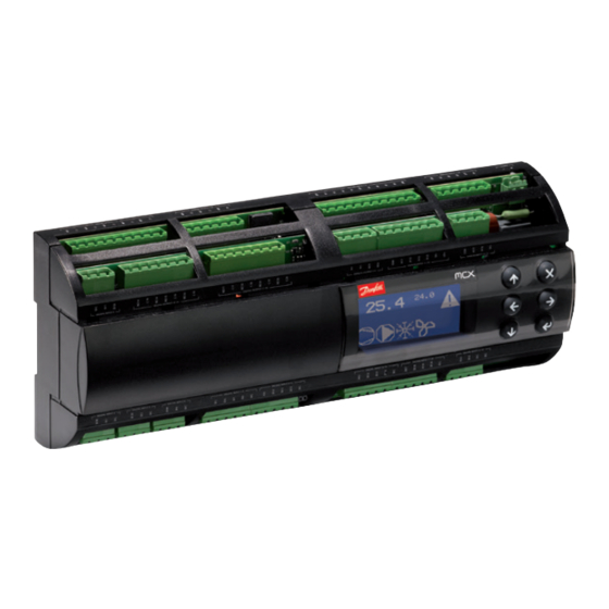
Electronic controller
MCX15B2/20B2
ANALOG INPUTS
NTC, 0/1 V, 0/5 V, 0 / 10 V PT1000, selectable via software
Universal NTC, Pt1000, 0/1 V, 0/5 V, 0/10 V, ON/OFF, 0/20 mA, 4/20 mA, selectable via
software
Total number
DIGITAL INPUTS
Voltage free contact/24V AC sensing
24/230 V AC optoinsulated
Total number
ANALOG OUTPUTS
0/10 V DC optoinsulated
0/10 V, PWM, PPM selectable via software
Total number
DIGITAL OUTPUTS
SPDT relay 16 A (changeover contacts)
SPST relay 5 A (normally open contacts)
Total number
OTHERS
Power supply 24-110-230 V AC / 40-230 V DC
Connection for programming key and for remote display and keyboard
Buzzer
RTC clock
Modbus RS485 serial interface
CANbus
Ethernet for Webserver/Modbus TCP
USB for firmware/application software update and datalogging
Dimensions (DIN modules)
Mounting
© Danfoss | DCS (vt) | 2020.10
General features:
MCX15B2/MCX20B2 is an electronic controller that stands on the top of the MCX range,
thanks to the large number of its inputs and outputs, the enhanced CPU capabilities and
connectivity features.
It holds all the typical functionalities of MCX controllers: programmability, connection to the
CANbus local network, up to two Modbus RS485 serial interfaces with galvanic isolation.
Furthermore, it is fitted with an ultra wide range (24/110/230 V AC) power supply in the
same product variant, with USB and Ethernet connection for embedded Web server and IP
protocols management.
It is available in several models, with or without graphic LCD display and with 15 or 20 digital
output.
080R9340
AN320819413085en-000401
MCX15B2
MCX20B2
4
6
6
10
10
16
18
18
4
4
22
22
6
6
2
2
6
6
2
2
13
18
15
20
•
•
•
•
-
-
•
•
x1
x2
•
•
•
•
•
•
16
16
DIN rail
DIN rail
AN320819413085en-000401 | 1
Advertisement
Table of Contents

Subscribe to Our Youtube Channel
Related Manuals for Danfoss MCX15B2


Summary of Contents for Danfoss MCX15B2
- Page 1 MCX15B2/20B2 AN320819413085en-000401 General features: MCX15B2/MCX20B2 is an electronic controller that stands on the top of the MCX range, thanks to the large number of its inputs and outputs, the enhanced CPU capabilities and connectivity features. It holds all the typical functionalities of MCX controllers: programmability, connection to the CANbus local network, up to two Modbus RS485 serial interfaces with galvanic isolation.
- Page 2 • Avoid touching or nearly touching the electronic components fitted on the board to avoid electrostatic discharges • The product is not suitable to be exposed directly to the Internet 2 | AN320819413085en-000401 © Danfoss | DCS (vt) | 2020.10...
-
Page 3: Technical Specifications
• 21 – 265 V AC, 50/60 Hz. Maximum power consumption: 15 W. Insulation between power supply and the extra-low voltage: reinforced • 40 – 230 V DC TYPE SPECIFICATIONS Total number: 16 on MCX20B2; 10 on MCX15B2 Analog inputs Analog Input type selectable via software Max 13.5 V input voltage... - Page 4 Max. baudrate (bps) Min. wire size Ethernet 10/100 M CANbus 1000 50 K AWG18 125 K AWG22 250 K AWG24 500 K AWG26 AWG26 RS485 1000 125 K AWG22 Signal wiring 4 | AN320819413085en-000401 © Danfoss | DCS (vt) | 2020.10...
-
Page 5: Connection Diagram
24 V SELV SELV BOTTOM BOARD NOTE: connection has to be made on the first and last local network units, make the connection as close as possible to the connector © Danfoss | DCS (vt) | 2020.10 AN320819413085en-000401 | 5... - Page 6 4 way screw plug-in connector type • pitch 5 mm • section cable 0.2 – 2.5 mm² CAN-RJ connector 6/6 way telephone RJ12 plug type USB DEV connector USB Mini B 6 | AN320819413085en-000401 © Danfoss | DCS (vt) | 2020.10...
-
Page 7: User Interface
MCX20B2, LCD, 4 SSR, 2xRS485, S 080G0332 Note: single pack codes (S) include standard kit connectors, industrial pack codes (I) don’t include standard kit connectors Accessories part numbers Description Code No. MCX20B2 CONNECTORS KIT 080G0404 © Danfoss | DCS (vt) | 2020.10 AN320819413085en-000401 | 7... - Page 8 AO: section = 0.5 mm² Connectors: Phoenix FKIC (or equivalent): Wire strip lenght = 10 mm Phoenix MSTP (or equivalent): End sleeves = PKD 508/PKD 108 (Danfoss P/N: 080G0404, provided with MCX15/20B2 Single Pack) Wiring kit (example) Phoenix FKIC Connector...
- Page 9 DO16-20 NO18 NO18 NO17 NO17 NO16 DIGITAL INPUT direct connection 3 ways direct connection 3 ways direct connection 3 ways direct connection 3 ways direct connection DI5-8 DI5-8 5 ways © Danfoss | DCS (vt) | 2020.10 AN320819413085en-000401 | 9...
-
Page 10: Analog Input
AO1-4 Phoenix FKIC 8 ways 6 ways 1910717 AO1-6 AO5-6 Phoenix FKIC 4 ways 1910694 NOTE: the AO signals in MCX20B2 are internally powered, therefore you must not connect L1 10 | AN320819413085en-000401 © Danfoss | DCS (vt) | 2020.10... -
Page 11: Digital Output
Connection diagram – from MCX15B to MCX15B2 Wiring Kit From the unit to Phoenix MSTB MCX15B to be (MCX15B2 MCX15B2 replaced Phoenix FKIC Wires connectors) board DIGITAL OUTPUT direct connection DO1-5 DO1-5 10 ways DO6-8 direct connection DO6-8 6 ways... - Page 12 6 ways DI18 DI18 DI19 DI20 DI18-22 DI21 DI22 NOTE: the DIC signals in MCX15B2 are internally connected, therefore you must ensure that DIC are connected to the same phase before the replacement. ANALOGUE INPUT direct connection AI1-6 AI1-6 11 ways...
- Page 13 Phoenix FKIC 11 ways 1910762 DO9-13 10 ways NC10 NO10 NC11 NO10 DO9-13 NO11 NO11 NC12 NO12 NO12 NO13 DO13 Phoenix FKIC 3 ways 1910681 External Relay NC13 24 VAC NO13 © Danfoss | DCS (vt) | 2020.10 AN320819413085en-000401 | 13...
- Page 14 Danfoss can accept no responsibility for possible errors in catalogues, brochures and other printed material. Danfoss reserves the right to alter its products without notice. This also applies to products already on order provided that such alterations can be made without subsequential changes being necessary eady agreed.
Need help?
Do you have a question about the MCX15B2 and is the answer not in the manual?
Questions and answers