Table of Contents
Advertisement
Quick Links
Getting started with the STEVAL-ESC002V1 electronic speed controller reference
Introduction
The
STEVAL-ESC002V1
electronic speed controller (ESC) reference design can be used with different kind of drones, from
small racing ones to bigger light drones used for surveying and any 3-phase BLDC application requiring a compact form factor
and high speed rotation performance.
Together with the
STSW-ESC002V1
The board is based on the
STSPIN32F0A
processor, voltage regulators, signal conditioning circuitry and gate drivers in a small 7x7 mm2 QFN package.
Power stage is based on the low resistance (2.8 mΩ) and high speed
technology and able to deliver up to 20 A of continuous current.
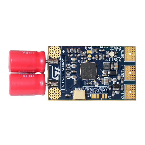
Figure 1.
STEVAL-ESC002V1 reference design: top view with bulk capacitors mounted
UM2518 - Rev 1 - December 2018
For further information contact your local STMicroelectronics sales office.
firmware package, it implements a sensorless voltage mode six-step driving.
advanced 3-phase brushless motor controller that embeds an ARM
STL140N6F7
MOSFETs, designed in STripFET™ F7
UM2518
User manual
design
®
®
Cortex
-M0
www.st.com
Advertisement
Table of Contents

Related Manuals for ST STEVAL-ESC002V1


Summary of Contents for ST STEVAL-ESC002V1
-
Page 1: Figure 1. Steval-Esc002V1 Reference Design: Top View With Bulk Capacitors Mounted
UM2518 User manual Getting started with the STEVAL-ESC002V1 electronic speed controller reference design Introduction STEVAL-ESC002V1 electronic speed controller (ESC) reference design can be used with different kind of drones, from small racing ones to bigger light drones used for surveying and any 3-phase BLDC application requiring a compact form factor and high speed rotation performance. -
Page 2: Safety Precautions
UM2518 Safety precautions Safety precautions Warning: Some of the components mounted on the board could reach hazardous temperature during operation. While using the board: • Do not touch the components • Do not cover the board • Do not put the board in contact with flammable materials or with materials releasing smoke when heated After operation, allow the board to cool down before touching it. -
Page 3: Main Features And Target Applications
Very compact and light design: 25 x 40.5 mm PCB size • RoHS and WEEE compliant The STEVAL-ESC002V1 reference design mainly targets light drones for professional and recreational purposes, and any 3-phase brushless application requiring a high speed rotation performance. UM2518 - Rev 1... -
Page 4: Hardware Overview
UM2518 Hardware overview Hardware overview STEVAL-ESC002V1 drives a single three-phase brushless motor. Figure 2. STEVAL-ESC002V1 components (top view) PWM input Battery positive input RGB LED TP6, TP7 To the battery PA5 and PA7 debug GPIOs Bulk capacitors (to be mounted) -
Page 5: Table 1. Test Points And Connectors
UM2518 Hardware overview Table 1. Test points and connectors Connector/ Test point Signal GPIO Description Power output U. CON1 OUTU It has to be connected to one of the motor phases Power output V CON2 OUTV It has to be connected to one of the motor phases Power output W CON3 OUTW... -
Page 6: Setup
1: positive on TP4 (round pad) and negative on TP5 (square pad). Figure 4. STEVAL-ESC002V1 PWM input from FCU connection details Step 4. Connect the board to the battery or to a DC power supply as indicated in Figure 1 (supply range is from 2S to 6S). -
Page 7: Figure 5. Steval-Esc002V1 Swd Connection Details
UM2518 Programming the board Figure 5. STEVAL-ESC002V1 SWD connection details Included connector When the board is connected to the SWD programmer, you can program it in two ways. Step 1. Write the binary included in the STSW-ESC002V1 firmware package or Step 2. -
Page 8: Board Pwm Flowchart And Interface Parameters
The firmware does not monitor the PWM signal frequency. The algorithm considers only the duration of the positive pulses. The STEVAL-ESC002V1 default behavior is described below. At power-up the motor is stopped. The ESC waits for at least BSP_BOARD_IF_TIMx_ARMING_VALID_TON pulses before arming (that is allowing the motor driving) the board. -
Page 9: Figure 6. Steval-Esc002V1 Default Behavior: Pwm Interface Flowchart
UM2518 Board PWM flowchart and interface parameters Figure 6. STEVAL-ESC002V1 default behavior: PWM interface flowchart Arm. Count = 0 Disarmed 1500 ms timeout Pulse detected expired? Arm. Count ++ Arm. Count > 10 Armed 1500 ms timeout Pulse detected expired? >... -
Page 10: Table 2. Pwm Interface Parameters
UM2518 Board PWM flowchart and interface parameters Table 2. PWM interface parameters Parameter Description Default BSP_BOARD_IF_TIMx_STOP_MS No-PWM timeout in ms 1500 BSP_BOARD_IF_TIMx_ARMING_VALID_TON Number of valid PWM pulses (any duration) arming the board Number of PWM pulses above minimum duration starting the BSP_BOARD_IF_TIMx_START_VALID_TON motor Number of PWM pulses below minimum duration starting the... -
Page 11: Schematic Diagrams
UM2518 Schematic diagrams Schematic diagrams Figure 7. STEVAL-ESC002V1 circuit schematic (1 of 3) 100nF VREG OP2P OP2P 680nF OP2N OP2N VBOOTU 10µF 100nF OP2O OUTU OP2O OUTU STSPIN32F0A 680nF VREG12 VBOOTV OUTV NRST OUTV 680nF VDDA VBOOTW 22µH OUTW OUTW... -
Page 12: Figure 9. Steval-Esc002V1 Circuit Schematic (3 Of 3)
UM2518 Schematic diagrams Figure 9. STEVAL-ESC002V1 circuit schematic (3 of 3) Power supply SWD prog. VBUS connector Feedback SWD CLK PA14 VBUS SWD IO PA13 SW CON SM03B-SRSS-TB Connector: VBUS Pre-crimped wire 150 mm SH3-SS5-28150 470k Housing 3 poles 1 mm... -
Page 13: Bill Of Materials
UM2518 Bill of materials Bill of materials Table 3. STEVAL-ESC002V1 bill of materials Item Q.ty Ref. Part / Value Description Manufacturer Order code CON1, CON2, RECT_PAD257R200D Connectors CON3 35_43 CON4, CON5 pad221hole35_43 Connectors C1, C3, C10, 100 nF 50 V ±10%... - Page 14 UM2518 Bill of materials Item Q.ty Ref. Part / Value Description Manufacturer Order code R2, R3, R4, 25 R 1/10 W ±5% Resistors R5, R6, R7 R0603 10 k 1/10 W ±1% R8, R9, R10 Resistors R0603 R11, R17, R18 1 k 1/10 W ±5% R0603 Resistors 10 k 1/10 W ±1% R12, R14, R16...
-
Page 15: Revision History
UM2518 Revision history Table 4. Document revision history Date Version Changes 17-Dec-2018 Initial release. UM2518 - Rev 1 page 15/19... -
Page 16: Table Of Contents
UM2518 Contents Contents Safety precautions..............2 Main features and target applications . - Page 17 STEVAL-ESC002V1 default behavior: PWM interface flowchart ........
- Page 18 STEVAL-ESC002V1 bill of materials........
- Page 19 ST’s terms and conditions of sale in place at the time of order acknowledgement. Purchasers are solely responsible for the choice, selection, and use of ST products and ST assumes no liability for application assistance or the design of Purchasers’...
Need help?
Do you have a question about the STEVAL-ESC002V1 and is the answer not in the manual?
Questions and answers