Table of Contents
Advertisement
Quick Links
UM3347
User manual
Control board for automotive applications - STEVAL-TTM007A
Introduction
The
STEVAL-TTM007A
control board features the advanced Stellar E automotive-grade microcontroller SR5 E1 E7 (Stellar E
32-bit Arm® Cortex®-M7 automotive MCU 2x cores) with functional safety performance (ASIL-D capability). The dedicated
peripheral designed for motor control renders it possible to develop and implement firmware architectures driving up to two
independent motors. The latest motor control connector facilitates compatibility with the STEVAL-APD03ACB and STEVAL-
APD04ACB driving boards from the dedicated electric traction kit capable of driving all the ACEPACK DRIVE product family
based on the latest SiC MOSFET technology. The CAN, UART, and programmer connectors offer several interfaces with the
MCU. The dedicated software tool
StellarStudio
for the Stellar E microcontroller family can be used to configure the STEVAL-
TTM007A for each application with a user-friendly GUI.
The integrated
SPSB100
AEC-Q100-qualified power management integrated circuit (PMIC) ensures appropriate power supply
to the microcontroller and connectivity from the low voltage battery level.
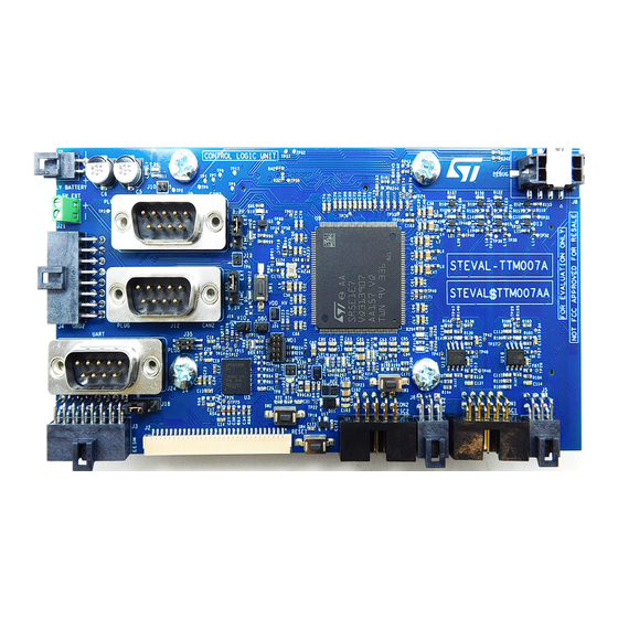
Figure 1.
STEVAL-TTM007A top view
Figure 2.
STEVAL-TTM007A bottom view
UM3347 - Rev 1 - September 2024
www.st.com
For further information contact your local STMicroelectronics sales office.
Advertisement
Table of Contents

Related Manuals for ST STEVAL-TTM007A


Summary of Contents for ST STEVAL-TTM007A
-
Page 1: Figure 1. Steval-Ttm007A Top View
UM3347 User manual Control board for automotive applications - STEVAL-TTM007A Introduction STEVAL-TTM007A control board features the advanced Stellar E automotive-grade microcontroller SR5 E1 E7 (Stellar E 32-bit Arm® Cortex®-M7 automotive MCU 2x cores) with functional safety performance (ASIL-D capability). The dedicated peripheral designed for motor control renders it possible to develop and implement firmware architectures driving up to two independent motors. -
Page 2: Evaluation Kit Features
UM3347 Evaluation kit features Evaluation kit features Control board MCU main features and functional characteristics 1.1.1 SR5E1 features • AEC-Q100 automotive qualification ongoing • SR5 high-performance analog MCU offering: – Digital and analog high-frequency control requested by new wide-bandgap technologies (SiC and GaN) –... -
Page 3: Enhanced Peripherals For Fast Control Loop Capability
UM3347 Evaluation kit features 1.1.6 Enhanced peripherals for fast control loop capability • 12 timers: – 2x HRTIM (Hi-Resolution and complex waveform builder): 12x 16-bit counters, 104 ps resolution, 24 PWM in total – 2x 16-bit 6-channel advanced control timers, with up to 12x PWM, in total –... -
Page 4: Target Applications
8 rail-to-rail analog comparators, 50 ns propagation delay • Hardware accelerator – 1× CORDIC for trigonometric functions acceleration Target applications The STEVAL-TTM007A is specifically designed for applications involving motor drives for: • e-trucks • e-cars UM3347 - Rev 1 page 4/48... -
Page 5: Safety And Operating Instructions
UM3347 Safety and operating instructions Safety and operating instructions General terms All operations involving transportation, installation, and use, as well as maintenance, has to be carried out by skilled technical personnel (national accident prevention rules must be observed). For the purpose of these basic safety instructions, "skilled technical personnel"... -
Page 6: Development Environment
This demo can be imported using Stellar Studio import wizard: 1. Select [File]>[New]>[Other…] 2. Select [Stellar/StellarStudio Import] wizard 3. Select the SR5E1-STEVAL-TTM007A control board and click [Next] 4. Choose sample application: SR5E1_STEVAL_TTM007A_TEST_PWM_BLINK_LED UM3347 - Rev 1 page 6/48... -
Page 7: Conventions
UM3347 Conventions Conventions The following table provides the conventions used for the ON and OFF settings in this document. Table 1. ON/OFF convention Convention Definition Jumper Jx ON Jumper fitted Jumper Jx OFF Jumper not fitted Jumper Jx [1-2] Jumper fitted between pin 1 and pin 2 Resistor Rx ON Resistor mounted Resistor Rx OFF... -
Page 8: Hardware Layout And Configuration
UM3347 Hardware Layout and Configuration Hardware Layout and Configuration The STEVAL-TTM007A evaluation board is designed around the Stellar-E microcontroller SR5E1E7 in a 176-pin LQFP package. The following figures and tables provide the following details: • How the connectivity and the interfacing elements between the board’s logic devices (MCU and PMIC) and the external tools useful for motor control application are arranged. -
Page 9: Figure 4. Steval-Ttm007A Bottom View: External Connectors
UM3347 Hardware Layout and Configuration Figure 4. STEVAL-TTM007A bottom view: external connectors. Table 2. STEVAL-TTM07A connector descriptions Connector Connector type Description Mating connectors identifier Connectors for dual GDB control: Power FI-S25P-HFE FI-S25S supply connection Connectors for dual GDB control: Logic signal... -
Page 10: Figure 5. Steval-Ttm007A Top View: Push Button Positions
Samtec Programming connector for MCU. Connect SWD1 SamtecFTSH-105-01-L-D-K here external debugger FFSD-05-D-06.00-01-N Figure 5. STEVAL-TTM007A top view: push button positions Table 3. Push button descriptions Button Switch type Description identifier It can be used to enter the NVM programming mode of the PMIC by pulling up the SWDBG pin of... -
Page 11: Figure 6. Steval-Ttm07A Led Positions
UM3347 Hardware Layout and Configuration Figure 6. STEVAL-TTM07A LED positions Table 4. LED descriptions Color Description identifier D4, D5, D6 Green If turned ON, they indicate the presence of respectively 12 V, 5V, 3.3 V. It is connected to the NFSO1 pin of the PMIC. NFSO1 is asserted low when a fault event is Green detected. -
Page 12: Quick Start
Selection of 5 V supply (external/PMIC)PMIC->default [1-2] Ignition command (default high level) [1-2] SWDBG pin (PMIC) connection selection (VDD/GND)GND->default SWDBG PMIC Input/Output power supply selection (external/PMIC)PMIC- If SPSB100 enabled: [2-3] >default Figure 7. STEVAL-TTM007A jumper positions UM3347 - Rev 1 page 12/48... -
Page 13: Power Supply
J29 and use [1-2]. Current Sensing Section The STEVAL-TTM007A provides two independent connectors that can be plugged with the output of current sensors like Hall effect sensors. The availability of the two current sensor connectors is related to the possibility of driving two independent motors simultaneously. -
Page 14: Figure 9. Current Sensing Connector Schematic
UM3347 Quick Start Table 7. Configurations available for current sensor supplies Resistors 3.3 V R1 ON and R2 ON Selected R3 OFF and R4 OFF R1 OFF and R2 OFF Selected R3 ON and R4 ON Figure 9. Current sensing connector schematic Figure 10. -
Page 15: Resolver Circuit Section For Position Sensing
Resolver circuit section for position sensing The STEVAL-TTM007A is predisposed to work with resolver position sensors. It has two independent connectors that can work with two resolvers, each related to a different motor, in compliance with the capability of the control board to support firmware for driving two motors. -
Page 16: Figure 12. Resolver Conditioning Circuit: Excitation Amplifying Stage
UM3347 Quick Start Figure 12. Resolver conditioning circuit: excitation amplifying stage. Figure 13. Resolver conditioning circuit: cosine and sine signal amplifying stages Table 10. RES1 and RES2 pinout PIN n° Connectors Connection EXC-_SENS: RES1/RES2 Negative terminal of EXCITATION signal EXC+_SENS: RES1/RES2 Positive terminal of EXCITATION signal SIN-_SENS:... - Page 17 UM3347 Quick Start Resolver Function Peripheral SAR4_IN3 SAR4_IN2 RES2 EXCITATION B-DAC2_OUT (enabled if R178 ON) Note: The resolver of Motor 2 must be enabled. By default, the resistor R178 is not mounted. To enable the functioning of the second position sensor R178 must be mounted. UM3347 - Rev 1 page 17/48...
-
Page 18: Board To Board Connections
UM3347 Board to board connections Board to board connections The STEVAL-APD03ACB can work with the latest power modules like the ACEPACK DRIVE. For the connection between the APD03ACB and the ACEPACK it is possible to follow the press fitting procedure already mentioned. The other interconnections required for a complete system to be tested or used are depicted in the following image. -
Page 19: Schematic Diagrams
Schematic diagrams Figure 15. STEVAL-TTM007A schematic diagram (1 of 10) CONTROL BOARD S P I1 CS S P I_CS S P I1 S CK S P I_CLK CONNECTOR FOR DUAL GDB BOARD CONTROL S P I1 MIS O S P I_MIS O... -
Page 20: Figure 16. Steval-Ttm007A Schematic Diagram (2 Of 10)
Figure 16. STEVAL-TTM007A schematic diagram (2 of 10) 0.1uF GND_C TP 2 TP 3 TP 1 CAN_H CAN_L CAN_Tx GND_C CAN_TX CAN_TX CANH CANL CAN_RX CAN_RX S HDN TCAN330GD TP 4 GND_C CAN_Rx J 10 GRP B021VWVN-RC GND_C GND_C GND_C... -
Page 21: Figure 17. Steval-Ttm007A Schematic Diagram (3 Of 10)
Figure 17. STEVAL-TTM007A schematic diagram (3 of 10) 0.1uF GND_C TP 6 TP 7 TP 5 CAN_H CAN_L CAN_Tx GND_C J 12 CAN_TX CAN_TX CANH CANL CAN_RX CAN_RX S HDN TCAN330GD TP 8 GND_C CAN_Rx J 13 GRP B021VWVN-RC GND_C... -
Page 22: Figure 18. Steval-Ttm007A Schematic Diagram (4 Of 10)
Figure 18. STEVAL-TTM007A schematic diagram (4 of 10) S te lla rE U Motor P ha s e Curre nt U Motor P ha s e Curre nt_M2 P ha s e _Curre nt_U P ha s e _Curre nt_U_M2... -
Page 23: Figure 19. Steval-Ttm007A Schematic Diagram (5 Of 10)
Figure 19. STEVAL-TTM007A schematic diagram (5 of 10) VDD BUCK1 3V3 VDD BUCK2 5V BUCK3 NOT USED PGND3_2 VIN3_2 PGND3_1 VIN3_1 PGND3_0 VIN3_0 VDD_BUCK1_3V3_MICRO VDD_BUCK2_5V Not mounte d BEST1 CLOSE TO PIN BEST2 VDD_BUCK1_3V3_MICRO VDD_BUCK2_5V 15uH 15uH 47nF 47nF PH1_1... -
Page 24: Figure 20. Steval-Ttm007A Schematic Diagram (6 Of 10)
Figure 20. STEVAL-TTM007A schematic diagram (6 of 10) HV_REFH_DAC VDD_HV_SD_DAC 3V3_Micro 3V3_Micro 330Ohm @ 100MHz 330Ohm @ 100MHz 10nF 10uF 0.047uF 10uF 0.047uF 10nF 5V_C HV_REFH_DAC VS S A HV_REFH_DAC_COMP HV_REFL_DAC VS S A HV_REFH_SAR VDD_HV_SAR HV_REFL_DAC_COMP VDD_HV_SD_DAC 3V3_Micro 3V3_Micro VDD_HV_S D_DAC_COMP 1.5k... -
Page 25: Figure 21. Steval-Ttm007A Schematic Diagram (7 Of 10)
Figure 21. STEVAL-TTM007A schematic diagram (7 of 10) 120Ohms @ 100MHz TP27 R100 10k E_RES_EXC+ E_RES_EXC- E_RES_EXC- E_RES_EXC+_TO_SENSOR E_RES_EXC-TO_SENSOR R101 TP28 E_RES_SIN+ E_RES_SIN- E_RES_SIN+ FROM SENSOR E_RES_SIN- FROM SENSOR 470R E_RES_EXC+ C110 E_RES_COS+ E_RES_COS- +5VC 120Ohms @ 100MHz E_RES_COS+ FROM SENSOR... -
Page 26: Figure 22. Steval-Ttm007A Schematic Diagram (8 Of 10)
Figure 22. STEVAL-TTM007A schematic diagram (8 of 10) 120Ohms @ 100MHz TP48 FB12 R135 10k E_RES_EXC+ E_RES_EXC- E_RES_EXC- E_RES_EXC+_TO_SENSOR E_RES_EXC-TO_SENSOR R136 TP46 E_RES_SIN+ E_RES_SIN- FB13 E_RES_SIN+ FROM SENSOR E_RES_SIN- FROM S ENS OR 470R E_RES_EXC+ C133 E_RES_COS+ E_RES_COS- +5VC 120Ohms @ 100MHz... -
Page 27: Figure 23. Steval-Ttm007A Schematic Diagram (9 Of 10)
Figure 23. STEVAL-TTM007A schematic diagram (9 of 10) C156 S T3232EBTR 0.1uF C157 C158 0.1uF GND_C J 24 GND_C T1OUT 0.1uF C159 0.1uF R1IN C160 R1OUT GND_uC T1IN T2OUT T2IN 0.1uF R2IN R2OUT GND_C UART_RXD UART_RXD GND_C UART_TXD UART_TXD UART - RS 232... -
Page 28: Figure 24. Steval-Ttm007A Schematic Diagram (10 Of 10)
Figure 24. STEVAL-TTM007A schematic diagram (10 of 10) TP 51 TP 50 TP 52 TP 53 TP 54 TP 49 MC_ADC_CURRENT_I1 R171 MC_ADC_CURRENT_I1_M2 R172 P has e _Curre nt_U P has e _Curre nt_U_M2 MC_ADC_CURRENT_I2 R173 MC_ADC_CURRENT_I2_M2 R174 MC_DIS 1_M1... -
Page 29: Bill Of Materials
UM3347 Bill of materials Bill of materials Table 12. STEVAL-TTM007A bill of materials ItemA7:G7 Q.ty Ref. Part/Value Description Manufacturer Order code CAP CER 0.22UF C1, C2 0.22uF TDK Corporation CGA3E3X7R1H224K080AB 50V X7R 0603 CAP TANT 47UF C3, C4 47uF KEMET... - Page 30 UM3347 Bill of materials ItemA7:G7 Q.ty Ref. Part/Value Description Manufacturer Order code C16, C17, C37, C40, C43, C46, C49, C52, C55, C57, C59, C61, C63, C65, CAP CER 10000PF Wurth C67, 10nF 885012206014 10V X7R 0603 Electronics Inc. C69, C71, C73, C75, C77,...
- Page 31 UM3347 Bill of materials ItemA7:G7 Q.ty Ref. Part/Value Description Manufacturer Order code C36, C39, C42, C45, C48, C51, C54, C56, C58, C60, C62, C64, C66, CAP CER 0.047UF Wurth 0.047uF 885012206118 C68, 100V X7R 0603 Electronics Inc. C70, C72, C74, C76, C78, C80,...
- Page 32 UM3347 Bill of materials ItemA7:G7 Q.ty Ref. Part/Value Description Manufacturer Order code C116, C119, C120, C122, C123, C127, C128, C131, CAP CER 150PF 150pF TDK Corporation CGA3E2C0G2A151J080AD C139, 100V C0G 0603 C142, C143, C145, C146, C150, C151, C154 C118, C125, CAP CER 47PF 47pF TDK Corporation...
- Page 33 UM3347 Bill of materials ItemA7:G7 Q.ty Ref. Part/Value Description Manufacturer Order code Everlight LED RED CLEAR Electronics Co 19-217/R6C-AL1M2VY/3T 2SMD LED GREEN OSRAM Opto USR2 DIFFUSED 0603 Semiconductors LP L296-J2L2-25-Z Inc. PTC RESET FUSE MINISMDC075F/33-2 Littelfuse Inc. MINISMDC075F/33-2 33V 750MA 1812 FB1, FB2, FB3,...
- Page 34 UM3347 Bill of materials ItemA7:G7 Q.ty Ref. Part/Value Description Manufacturer Order code CONN HEADER J16, J29 CON 3 Strip 1.27 VERT 3POS Harwin Inc. M50-3530342 1.27MM CONN JUMPER Sullins J17, J19, Jumper_Female SHORTING .100" Connector QPC02SXGN-RC GOLD Solutions J18, J20, CONN HEADER Wurth con3-strip-male...
- Page 35 UM3347 Bill of materials ItemA7:G7 Q.ty Ref. Part/Value Description Manufacturer Order code R1, R2, R14, R15, R19, R20, R24, R25, R27, R28, R54, R60, R84, R85, R87, R88, R91, R92, R93, R95, R97, R98, R99, R177, RES SMD 0 OHM Panasonic R184, JUMPER 1/10W...
- Page 36 UM3347 Bill of materials ItemA7:G7 Q.ty Ref. Part/Value Description Manufacturer Order code Thick Film Resistors - SMD CRGCQ TE Connectivity CRGCQ0603F330R 0603 330R 1% SMD Resistor R13, R201, R202, RES SMD 150 R207, OHM 1% 1/10W Yageo RC0603FR-07150RL R208, 0603 R214, R217 RES SMD 120...
- Page 37 UM3347 Bill of materials ItemA7:G7 Q.ty Ref. Part/Value Description Manufacturer Order code R52, R53, R55, R56, R59, R64, R67, R81, R82, R83, R170, R178, RES SMD 0 OHM Panasonic R179, JUMPER 1/10W Electronic ERJ-3GEY0R00V R185, 0603 Components R186, R187, R189, R193, R194, R197,...
- Page 38 UM3347 Bill of materials ItemA7:G7 Q.ty Ref. Part/Value Description Manufacturer Order code R100, R103, R106, R107, R108, R109, R110, R113, R128, R135, R138, RES SMD 10K R141, OHM 1% 1/10W Yageo RC0603FR-0710KL R142, 0603 R143, R144, R145, R148, R163, R216, R218, R219, R220,...
- Page 39 UM3347 Bill of materials ItemA7:G7 Q.ty Ref. Part/Value Description Manufacturer Order code R120, R131, RES 20K OHM 1% Yageo RC0603FR-1015KL R155, 1/10W 0603 R166 R129, RES 10K OHM 1% Yageo RC0603FR-1010KL R164 1/10W 0603 RES SMD 5.1K R134, 5.1k OHM 0.1% 1/10W Yageo RT0603BRD075K1L R169...
- Page 40 UM3347 Bill of materials ItemA7:G7 Q.ty Ref. Part/Value Description Manufacturer Order code TEST POINT 1MM TP3, TP7 CAN_L SMD PADSTASCK TP4, TP8, TP16, TP27, TP28, TP29, TP30, TP31, TP32, TP33, TP34, TP35, TP36, TP37, TP38, TP39, TP40, TP41, TP42, TEST POINT 1MM TP43, CAN_Rx SMD PADSTASCK...
- Page 41 UM3347 Bill of materials ItemA7:G7 Q.ty Ref. Part/Value Description Manufacturer Order code TEST POINT 1MM TP22 SMD PADSTASCK TEST POINT 1MM TP23 VDD_LV_SMPS SMD PADSTASCK TEST POINT 1MM TP24 NMOS SMD PADSTASCK TEST POINT 1MM TP25 VDD_LDO1 SMD PADSTASCK TEST POINT 1MM TP26 VDD_LDO2 SMD PADSTASCK...
-
Page 42: Board Versions
UM3347 Board versions Board versions Table 13. STEVAL-TTM007A versions Finished good Schematic diagrams Bill of materials STEVAL$TTM007AA schematic diagrams STEVAL$TTM007AA bill of materials STEVAL$TTM007AA 1. This code identifies the STEVAL-TTM007A evaluation board first version. UM3347 - Rev 1 page 42/48... -
Page 43: Regulatory Compliance Information
UM3347 Regulatory compliance information Regulatory compliance information Notice for US Federal Communication Commission (FCC) For evaluation only; not FCC approved for resale FCC NOTICE - This kit is designed to allow: (1) Product developers to evaluate electronic components, circuitry, or software associated with the kit to determine whether to incorporate such items in a finished product and (2) Software developers to write software applications for use with the end product. -
Page 44: Revision History
UM3347 Revision history Table 14. Document revision history Date Version Changes 17-Sep-2024 Initial release. UM3347 - Rev 1 page 44/48... -
Page 45: Table Of Contents
UM3347 Contents Contents Evaluation kit features ............. 2 Control board MCU main features and functional characteristics . - Page 46 STEVAL-TTM007A bottom view: external connectors........
- Page 47 STEVAL-TTM007A bill of materials........
- Page 48 ST’s terms and conditions of sale in place at the time of order acknowledgment. Purchasers are solely responsible for the choice, selection, and use of ST products and ST assumes no liability for application assistance or the design of purchasers’...
Need help?
Do you have a question about the STEVAL-TTM007A and is the answer not in the manual?
Questions and answers