
Related Manuals for SEW-Eurodrive MOVIDRIVE DRS11A


Summary of Contents for SEW-Eurodrive MOVIDRIVE DRS11A
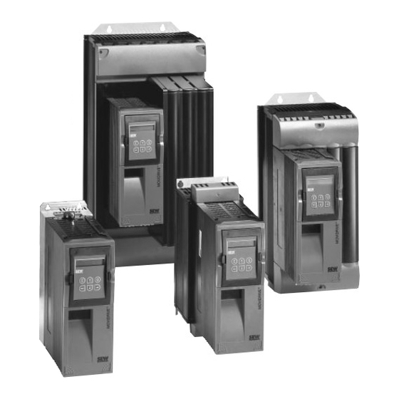
- Page 1 ® MOVIDRIVE Drive Inverters Manual Synchronous Operation Type DRS11A Edition 04/99 10/262/97 ® ®...
- Page 2 (→ Sec. X.X) means: Further information can be found in section X.X of this manual. • Each unit is manufactured and tested to current SEW-EURODRIVE technical standards and specifications. A requirement of fault-free operation and fulfilment of any rights to claim under guarantee is that this information is observed.
-
Page 3: Table Of Contents
Contents Page Introduction ....................4 1.1 Description ........................4 1.2 Block Diagram for Synchronous Operation..............6 Project Planning ..................7 2.1 Sample Applications ......................7 2.2 Project Planning Notes ....................9 2.3 Synchronous Operation with Open-circuit Monitoring of the Encoder Connection ..10 2.4 Synchronous Start/Stop .................... -
Page 4: Introduction
Introduction Introduction Description The "synchronous operation" process permits a group of motors to be operated with synchronous angular rotation or else with an adjustable proportional relation (electronic gear unit). The master drive is the one which specifies the position. It can also be an incremental encoder. The slave drive is the one which has to follow this position specification. - Page 5 Introduction • Mode 6/7: The angular difference resulting from free-running operation is reduced back down to zero in synchronous operation. During synchronous operation (X40:1 = "0"), the internal differ- ence counter is additionally used for correction to an adjustable offset angular deviation between master and slave.
-
Page 6: Block Diagram For Synchronous Operation
Introduction Block Diagram for Synchronous Operation 01523AEN Fig. 1: Block diagram for synchronous operation ® MOVIDRIVE Synchronous Operation DRS11A... -
Page 7: Project Planning
Project Planning Project Planning Sample Applications 1. Group configuration: Master and equal slaves e.g. multiple column hoist Slave 3 Slave 1 Slave 2 Master speed n2 speed n2 speed n2 speed n1 01363AEN Fig. 2: Group configuration 2. Master-slave chain: e.g. conveyor belts connected one after the other Master 4 Master 2 Master 3... - Page 8 Project Planning 3. Master-slave chain with external master incremental encoder: Encoder with external voltage supply Master 4 Master 2 Master 3 Master 1 slave 3 slave 1 slave 2 speed n4 speed n2 speed n3 speed n1 01366AEN Fig. 4: Master-slave chain with external master incremental encoder 4.
-
Page 9: Project Planning Notes
Project Planning Project Planning Notes • Do not use synchronous operation on systems with a rigid mechanical connection. • Ensure that the slave inverter is equipped with a braking resistor. • When planning the synchronous operation application, note that the slave has to be able to reduce the angle differential in respect of the master to zero at any time. -
Page 10: Synchronous Operation With Open-Circuit Monitoring Of The Encoder Connection
Project Planning Synchronous Operation with Open-circuit Monitoring of the Encoder Connection Fault-free transmission of the incremental encoder signals is necessary to guarantee permanent synchronous operation of the master and slave drive. To do this, open-circuit monitoring of the connection from master X14 (incremental encoder simulation) to slave X42 (master encoder input) is necessary. - Page 11 Project Planning The following table clarifies the settings and/or wire connections in the aforementioned master/ slave combinations with regard to synchronous starting/stopping and active open-circuit monitor- ing master/slave: Master Slave Master parameters Slave parameters Remarks Master: Incremental Open-circuit monitoring: Open-circuit monitoring: enc.
-
Page 12: Synchronous Operation With Sync. Encoder
Project Planning Synchronous Operation with Sync. Encoder In all applications involving friction-locked power transmission between the motor shaft and the machine, in which case slip is to be expected, it is necessary for position measurement to take place using an additional incremental encoder. This incremental encoder is mounted in a positive- locked connection to the driven machine part (it is fitted to a section of the machine) and is referred to as a sync. -
Page 13: Installation
Installation Installation Installation Instructions • The maximum permitted cable lengths are: - Between the master inverter and the slave inverters: 10 m - Between the inverters and the corresponding incremental encoders (MDV) / resolvers (MDS): 100 m • Connection cables of the incremental encoders (motor and sync. encoder) and all cables "incre- mental encoder simulation", "input master encoder"... -
Page 14: Movidrive ® Slave Connection................................................. 14
Installation ® ® MOVIDRIVE Master - MOVIDRIVE Slave Connection ® X13: MOVIDRIVE slave DIØØ /Controller inhibit DIØ1 CW/stop* DIØ2 CCW/stop* DIØ3 Enable/rapid stop* Open-circuit monitoring DIØ4 DRS MASTER STOPPED DIØ5 DRS SLAVE START DCOM Reference X13:DIØØ...DIØ5 VO24 +24V output DGND Ref. -
Page 15: Movitrac 31C Master - Movidrive ® Slave Connection
Installation ® ® MOVITRAC 31C Master - MOVIDRIVE Slave Connection ® X13: MOVIDRIVE slave DIØØ /Controller inhibit DIØ1 CW/stop* DIØ2 CCW/stop* DIØ3 Enable/rapid stop* Open-circuit monitoring DIØ4 DRS MASTER STOPPED DIØ5 DRS SLAVE START Synchronous DCOM Reference X13:DIØØ...DIØ5 start/stop VO24 +24V output DGND Ref. -
Page 16: Incremental Encoder Master - Movidrive ® Slave Connection
Installation ® Incremental Encoder Master - MOVIDRIVE Slave Connection ® X13: MOVIDRIVE slave DIØØ /Controller inhibit DIØ1 CW/stop* DIØ2 CCW/stop* DIØ3 Enable/rapid stop* DIØ4 DRS MASTER STOPPED DIØ5 DRS SLAVE START DCOM Reference X13:DIØØ...DIØ5 VO24 +24V output DGND Ref. potential for binary signals ST11 RS-485+ ST12... -
Page 17: Functional Description Of The "Drs11A Synchronous Operation Option" Terminals
Installation Functional Description of the "DRS11A Synchronous Operation Option" Terminals Terminal Function X40: "0" signal = synchronous operation INØ: Free-running operation "1" signal = free-running operation IN1: Offset 1 "0" signal = no Offset, with "1" signal on IN1, IN2 or IN3 the offset 1, 2 or 3 (P225, P226 or P227 becomes effective. -
Page 18: Startup
Startup Startup Introduction The following example describes the startup procedure for the synchronous operation of a two-col- umn hoist. Both drives are fitted with identical gear units with the identical ratio. The rated power values of the motor and the inverters are identical. In both drives, CW rotation of the motor means an upward movement of the hoist. -
Page 19: Summary Of Startup Procedure
Startup Summary of Startup Procedure The following diagram shows the procedure: Preliminary Work - Check wiring, terminal assignments and safety cut-outs. Disconnect drives from machine! → Sec. 4.3 - Carry out speed controlled start up of master and slave separately . - Program binary inputs and outputs according to application. -
Page 20: Preliminary Work
Startup Preliminary Work Make sure that • the wiring, • the terminal assignments • and the safety cut-outs have been implemented correctly in accordance with the application. Disconnect the drives from the machine so both drives can be mechanically operated independ- ently of one another. -
Page 21: Setting The Synchronous Operation Parameters
Startup 4.4.3 Setting the Synchronous Operation Parameters • Parameter input of the master and slave gear factors (P221 and P222). - P221 and P222 can be left at the factory setting of 1 when identical gear units are used with identical ratio and identical reduction ratio. -
Page 22: Examples For The Calculation Of P221 And P222
Startup Examples for the Calculation of P221 and P222 4.6.1 Example 1 This example will demonstrate the operation of two chain conveyors in synchronous operation. This is a positive-locked application with varying gear ratios. A synchronous encoder is not neces- sary, as in positive-locked applications the position data can be calculated from the signal of the motor encoder. -
Page 23: Example 2, Synchronous Encoder Application
Startup 4.6.2 Example 2, Synchronous Encoder Application This example will demonstrate the operation of two belt conveyors in synchronous operation. This is a force-locked application with identical gear ratios. In force-locked applications, the position data cannot be accurately calculated from the signal of the motor encoder, for this reason a master encoder is necessary on the first belt and a synchronous encoder on the second belt. -
Page 24: Parameters
Parameters Parameters Explanation of the parameters: the factory setting is identified by underlining in each case. Parameters can only be changed in the INHIBITED inverter status (= output stage at high resist- ance). Relationship between Parameter Values and Output Speed In the case of the adjustable parameters (P224, P225, P226, P227, P510, P511, P512, P514), it is necessary to enter increments which relate to an angle offset (e.g. - Page 25 Parameters The following additional parameters are available for synchronous operation. (Complete parameter list → MOVIDRIVE ® manual/operating instructions) Par. Name Adjustment range After Description Factory setting startup 22_ Synchronous control (only parameter set 1) 220 P-gain (DRS) 1...10...200 Gain of synchronous operation controller in the slave 221 Master gear factor 1...3,999,999,999...
-
Page 26: Explanation Of The Parameters
Parameters Explanation of the Parameters Synchronous operation control (only parameter set 1) P-gain (DRS) Adjustment range: 1...10...200 Gain of the synchronous operation controller in the slave. This determines the control characteristics of the slave as a function of the angular differences in respect of the master. The greater the P-gain setting, the faster any angular difference is corrected (although there is also a greater tendency towards oscillation). - Page 27 Parameters X40:2... Slave counter Mode Function Description X40:1 X40:4 (P224) (red) Free-running A "1" signal to X40:1 (pulse time > 100 ms) initiates start Effec- Effective operation of free-running. Free-running operation ends when the tive effective - limited by value angular difference reaches the value in P224.
- Page 28 Parameters Offset 1 [inc.] (X40:2) Offset 2 [inc.] (X40:3) Offset 3 [inc.] (X40:4) Adjustment range: -32,767...-10 / 10...32,767 inc.; effective only in mode 6 or mode 7! For mode 6 (angle offset at times): Three separately adjustable angular differences to which the slave sets itself for the duration of the "1" signal at X40:2 / X40:3 / X40:4.
- Page 29 Parameters Adv. warn. lag error [inc.] Adjustment range: 50...99.999.999 inc. An advance warning message is generated if the angle offset exceeds the value set here. This is independent of the operating mode of the slave drive. The DRS ADV. WARN. message can be used as a position message, for example, and be programmed on a binary output (P62_/P63_).
- Page 30 Parameters 60_/61_ Binary inputs The programmable binary inputs can be assigned four additional types of signal for synchronous operation. • DRS SET ZERO PT. The internal counter for the angle offset can be zeroed. "1" signal = Counter is zeroed. "1"...
- Page 31 Parameters Reaction to LAG ERROR It is possible to program the reaction to a fault message generated by exceeding the lag error limit (→ P512): Reaction Description NO REACTION No fault is displayed, nor is there any fault response. The signalled fault is com- pletely ignored.
-
Page 32: Fault Messages
Fault Messages Fault Messages The following fault messages may occur specifically in synchronous running: (For the complete list of faults → MOVIDRIVE ® manual/operating instructions). Fault Designation Possible cause Response code Encoder - Encoder cable or shield not connected cor- Check encoder cable and shield are con- rectly nected correctly;... -
Page 33: Technical Data
Technical Data Technical Data Option Synchronous operation card type DRS11A Part number 822 319 X ≈ 3.0 kΩ, PLC compatible Binary inputs X40:INØ ≈ 10 mA, sampling interval: 5 ms ...IN5 Signal level +13 V...+30 V "1" -3 V...+5 V "0"... - Page 34 SEW-EURODRIVE GmbH & Co · P.O.Box 30 23 · D-76642 Bruchsal/Germany Tel. +49-7251-75-0 · Fax +49-7251-75-19 70 · Telex 7 822 391 http://www.SEW-EURODRIVE.com · sew...
Need help?
Do you have a question about the MOVIDRIVE DRS11A and is the answer not in the manual?
Questions and answers