Satel Integra 24 Installer Manual
Alarm control panels
Hide thumbs
Also See for Integra 24:
- Manual (117 pages) ,
- Programming manual (103 pages) ,
- User manual (75 pages)
Table of Contents
Advertisement
Quick Links
Advertisement
Table of Contents

Related Manuals for Satel Integra 24


Summary of Contents for Satel Integra 24
- Page 1 INSTALLER MANUAL GDAŃSK integra_i_e 07/06...
- Page 2 (European Directives 91/157/EEC and 83/86/EEC). DECLARATION OF CONFORMITY Products: CA424P, CA832, CA16128P Manufacturer: SATEL spółka z o.o. - mainboards of INTEGRA control ul. Schuberta 79 panels. 80-172 Gdańsk, POLAND - INTEGRA 24 tel.
-
Page 3: Table Of Contents
7.2 Technical data - keypads ......................27 7.3 Technical data - expansion modules..................28 7.4 Battery selection........................29 7.4.1 INTEGRA 24 – battery 7Ah.......................29 7.4.2 INTEGRA 32 – battery 7Ah.......................29 7.4.3 INTEGRA 32 – battery 17Ah......................30 7.4.4 INTEGRA 64/128 – battery 17Ah......................30... -
Page 4: Introduction
• Possibility of system development by adding the expansion modules (the development extent depending on the control panel size). Creation of a system based on modules (including the wireless system controller of SATEL manufacture) installed at various places throughout the facility can considerably reduce the amount of cabling used. -
Page 5: System Components
• Additional function of the control panel RS-232 port, i.e. controlling the external analog modem, ISDN modem, GSM module, ISDN module and ETHM-1 module of SATEL manufacture, enables communication to be established with the service computer. In this case, the remote programming via telephone network or Ethernet as well as the service are as quick as direct programming from the computer via RS-232 port. - Page 6 SATEL INTEGRA Dedicated power outputs for keypads, expanders and detectors Outputs, OC type, mainboard Outputs, system 20+4* Connectors for voice synthesizers Keypads, system Expander buses Expanders, system Zone expanders Output expanders Objects Partitions Timers Telephone numbers for messaging Pager messages...
-
Page 7: Lcd Keypads
INT-SZ-GR / INT-SZ-BL / INT-SZK-GR. Code Lock. Enables performance of the access control functions and operation of the electromagnetic door lock. CA-64 SR. Expander of Proximity Card Reader. Supports the SATEL made proximity card readers to enable performance of the access control functions and operation of the electromagnetic door lock. - Page 8 SATEL INTEGRA CA-64 O-OC / CA-64 O-R / CA-64 O-ROC. Output Expander. Enables expansion of the system by 8 outputs. Made in three versions: 8 OC type outputs, 8 relay outputs and 4 relay outputs / 4 OC outputs. CA-64 OPS-OC / CA-64 OPS-R / CA-64 OPS-ROC. Output Expander with Power Supply.
-
Page 9: Control Panel Installation
- CA-6 OBU N (INTEGRA 24 and INTEGRA 32). - OMI-3 (INTEGRA 64, INTEGRA 128) – required for conformance to Standard 50131-3, - OMI-2 (INTEGRA 24, INTEGRA 32) – required for conformance to Standard 50131-3, - OMI-1 (INTEGRA 24) – required for conformance to Standard 50131-3. - Page 10 MEMORY INTEGRA 64 / INTEGRA 128 control panel mainboard RESET DIALER SYNT1 SYNT2 BATTERY CHARGE 500mA 1000mA OUT5 OUT6 OUT5 SERIAL PORT RS-232 CHARGE OUT6 OUT7 OUT7 OUT8 OUT8 OUT9 OUT9 OUT10 OUT10 OUT11 OUT11 OUT1 OUT2 OUT3 OUT4 +KPD +EX1/EX2 OUT12 OUT12 OUT13...
- Page 11 INTEGRA Installer Manual INTEGRA 32 control panel mainboard MEMORY RESET BATTERY CHARGE 350mA CHARGE 700mA DIALER OUT3 OUT1 OUT2 OUT3 OUT4 OUT4 OUT5 SERIAL PORT RS-232 OUT5 OUT6 OUT6 OUT7 OUT7 OUT8 OUT8 COMOUT1COM OUT2COM+KPDDTM CKM COM +EX DT CK AUX Z1 COM Z2 Z3 COM Z4 Z5 COM Z6 Z7 COM Z8 black...
-
Page 12: Connecting Lcd Keypads
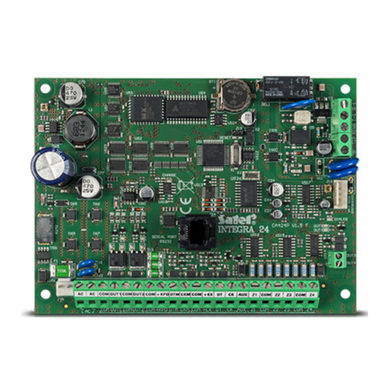
SATEL INTEGRA INTEGRA 24 control panel mainboard MEMORY RESET CHARGE DIALER OUT1 OUT2 OUT3 OUT4 SERIAL PORT RS-232 OUT3 OUT4 COMOUT1COM OUT2COM+KPDDTM CKM COM +EX DT CK AUX Z1 COM Z2 Z3 COM Z4 black Board terminals : ~ AC... - Page 13 INTEGRA Installer Manual To ensure correct operation of the keypads it is important that the cable resistance be kept as low as possible. For example: depending on the distance between the keypad and the control panel, the number of parallel-connected wires for particular signals (with the DY8x0,5 cable), must be as indicated in the table below.
- Page 14 SATEL INTEGRA Fig. 3. Partial view of INT-KLCDS-GR / INT-KLCDS-BL keypad board. Fig. 4. Partial view of INT-KLCDK-GR keypad board. Explanations to Figures 2, 3 and 4: 1 – buzzer 2 – tamper contact 3 – RS-232 port...
- Page 15 Z1 and Z2. They are served by the control panel in the same way as the mainboard zones. Numbers of Z1, Z2 zones in security system Keypad INTEGRA 24 INTEGRA 32 INTEGRA 64 INTEGRA 128...
-
Page 16: Connection Of Expansion Modules
SATEL INTEGRA Notes: • For the LCD keypads to be properly supported by the INTEGRA control panel, the keypad identification function must be performed after setting the keypad addresses. • Setting the same address in several keypads will trigger the tamper alarm, and also will display the "This keypad is changed"... - Page 17 INTEGRA Installer Manual Data exchange is carried out via DT1 (DT), CK1 (CK), and COM on the first bus, and via DT2, CK2 and COM on the second bus. Additionally, separate terminals for supplying the modules are provided in the mainboard connectors. The modules may be connected with the use of a typical unscreened cable used in alarm systems (for example, DY8x0,5).
- Page 18 SATEL INTEGRA EXPANDER A Z5 COM Z6 Z7 COM Z8 up to 1000m EXPANDER B Z5 COM Z6 Z7 COM Z8 EXPANDER C WITH POWER SUPPLY OR ADDITIONAL POWER SUPPLY Z5 COM Z6 Z7 COM Z8 Fig. 8. Connection of module group located far from the control panel.
-
Page 19: Connection Of Detectors
INTEGRA Installer Manual Notes: • The control panel does not handle the module unless the identification function is completed with the “Found xx exp. (yy new)" message. • A wrong module connection can make the correct identification of modules impossible, which is signaled by the message: “Error! Two expanders have the same addr. - Page 20 SATEL INTEGRA INTEGRA 64 / INTEGRA 128 OUT4 COM +KPD DTM COM +EX1 DT1 CK1 COM +EX2 DT2 CK2 Z1 COM Z2 Z3 COM Z4 COM 12V Fig. 9. Example of connecting NC type detector to control panel (NO type detector is to be connected in the same way).
- Page 21 INTEGRA Installer Manual INTEGRA 64 / INTEGRA 128 OUT4 COM +KPD DTM COM +EX1 DT1 CK1 COM +EX2 DT2 CK2 Z1 COM Z2 Z3 COM Z4 COM 12V EOL/NC Fig. 11. Example of connecting NC type detector in EOL configuration to control panel. INTEGRA 64 / INTEGRA 128 OUT4 COM +KPD DTM...
-
Page 22: Connection Of Sirens
SATEL INTEGRA EXPANDER EXPANDER HOUSING TAMPER CONTACT Z5 COM Z6 Z7 COM Z8 2x1,1kΩ IMPORTANT! DETECTOR SUPPLY COMMON AND SIGNAL NC NC TMP TMP COM 12V COMMON SHOULD BE CONNECTED WITH SEPARATE WIRE DETECTOR Fig. 13. Connection of 2EOL detector to expander when there is small distance between the control panel and the expander (the detector is distant from the expander). -
Page 23: Connection Of Telephone Line
INTEGRA Installer Manual control panel indicates the “No output load" trouble, connect a 2.2kΩ resistor in parallel to the load. • When the siren connected to the output in parallel to the resistor 2.2kΩ generates undesirable sounds (if not controlled), reduce the resistance value. Ω... -
Page 24: Connection Of Voice Synthesizers
SYNT1 or SYNT2 connectors on the INTEGRA 64 / INTEGRA 128 boards, or to the SM-2 VOICE SYNTHESIZER connector on the INTEGRA 24 / INTEGRA 32 boards. 4.7 Connection of printer... -
Page 25: Connection Of Power Supply
(e.g.: APS -15, APS-30 manufactured by SATEL). Table 1 (at the end of this manual) shows an example of estimated balance of current consumption by the system, and an example of battery selection for particular INTEGRA mainboards. -
Page 26: Starting The Control Panel
SATEL INTEGRA The above mentioned power-up sequence (battery first, then 230VAC mains) will enable the power supply unit and control panel electronic protection circuits to work properly, thus avoiding any defects of the alarm system components caused by possible installation errors. -
Page 27: Compliance With Clc/Ts 50131-3 Requirements
INTEGRA Installer Manual question about saving the settings appears when exiting the service mode). After the settings are checked, the control panel starts working. Notes: • If an error in the control panel program is detected, the “Load correct program to control panel"... -
Page 28: Basic Specifications
SATEL INTEGRA 7. Basic specifications 7.1 Technical data - alarm control panels Control panel type INTEGRA INTEGRA INTEGRA INTEGRA Mainboard supply voltage, nominal 18V AC, 50-60Hz 20V AC 50-60Hz (±10%) minimum 110mA 115mA 135mA Mainboard current typical 121mA 127mA 149mA... -
Page 29: Technical Data - Keypads
INTEGRA Installer Manual 7.2 Technical data - keypads Keypad type INT-KLCD-GR INT-KLCDR-GR INT-KLCDL-GR INT-KLCDS-GR INT-KLCDK-GR INT-KLCD-BL INT-KLCDR-BL INT-KLCDL-BL INT-KLCDS-BL Supply voltage, nominal (±15%) 12V DC minimum 15mA 55mA 25mA 55mA 30mA Current typical 17mA 60mA 30mA 61mA 33mA consumption maximum 101mA 156mA 110mA... -
Page 30: Technical Data - Expansion Modules
SATEL INTEGRA 7.3 Technical data - expansion modules Module type INT-S-GR CA-64 E CA-64 EPS CA-64 O CA-64 OPS CA-64 PP CA-64 ADR ADR-MOD CA-64 SM INT-S-BL Supply voltage, nominal 12V DC 12V DC 18V AC 12V DC 18V AC... -
Page 31: Battery Selection
30 hours on emergency power supply, while being able to remotely report the on the power supply trouble. 7.4.1 INTEGRA 24 – battery 7Ah The available 30 hr current for the 7Ah battery is: = 7Ah/30h ≈0.233A (233mA) -
Page 32: Integra 32 - Battery 17Ah
An efficient security system does not prevent burglary, assault or fire from happening, however it diminishes the risk that such a situation will cause no alarm or notification. Therefore, the SATEL Company recommends that operation of the whole security system be regularly tested. - Page 33 INTEGRA Installer Manual All circuits are designated by their version and date. The program periodically checks the memory content. The program run is supervised by hardware means. If a memory error occurs, the trouble signal is generated. In case of a run-time error, the processor is restarted.
- Page 34 SATEL sp. z o.o. ul. Schuberta 79 80-172 Gdańsk POLAND tel. + 48 58 320 94 00 info@satel.pl www.satel.pl...
Need help?
Do you have a question about the Integra 24 and is the answer not in the manual?
Questions and answers