Graco InvisiPac GS35 Plug-Free Instructions - Parts Manual
Hot melt applicator
Hide thumbs
Also See for InvisiPac GS35 Plug-Free:
- Instruction manual (52 pages) ,
- Instructions-parts list manual (52 pages) ,
- Instructions-parts list manual (52 pages)
Table of Contents
Advertisement
Quick Links
Instructions-Parts
InvisiPac™ GS35 Plug-Free™
Hot Melt Applicator
For dispensing hot melt adhesive. For professional use only.
Not approved for use in explosive atmospheres or hazardous locations.
Important Safety Instructions
Read all warnings and instructions in this manual. Save these
instructions.
1500 psi (10.3 MPa, 103 bar)
Maximum Working Fluid Pressure
80 psi (0.5 MPa, 5.5 bar) Maximum
Air Pressure
See page 6 for models and approval
information.
PROVEN QUALITY. LEADING TECHNOLOGY.
3A2805B
EN
Advertisement
Table of Contents

Related Manuals for Graco InvisiPac GS35 Plug-Free


Summary of Contents for Graco InvisiPac GS35 Plug-Free
- Page 1 Instructions-Parts InvisiPac™ GS35 Plug-Free™ 3A2805B Hot Melt Applicator For dispensing hot melt adhesive. For professional use only. Not approved for use in explosive atmospheres or hazardous locations. Important Safety Instructions Read all warnings and instructions in this manual. Save these instructions.
-
Page 2: Table Of Contents
Install Nozzle ..........11 Parts..............22 Operation ............11 Kits and Accessories........... 30 Pressure Relief Procedure......11 Dimensions ............32 Maintenance ............12 Technical Data ........... 33 Replace Inlet Filter ........12 Graco Standard Warranty........34 Troubleshooting..........13 Check Module..........15 3A2805B... -
Page 3: Warnings
Warnings Warnings The following warnings are for the setup, use, grounding, maintenance, and repair of this equipment. The exclamation point symbol alerts you to a general warning and the hazard symbols refer to procedure-specific risks. When these symbols appear in the body of this manual or on warning labels, refer back to these Warnings. - Page 4 Warnings WARNING FIRE AND EXPLOSION HAZARD • Use equipment only in well ventilated area. • Eliminate all ignition sources; such as pilot lights, cigarettes, portable electric lamps, and plastic drop cloths (potential static arc). • Keep work area free of debris, including solvent, rags and gasoline. •...
- Page 5 Warnings WARNING PERSONAL PROTECTIVE EQUIPMENT Wear appropriate protective equipment when in the work area to help prevent serious injury, including eye injury, hearing loss, inhalation of toxic fumes, and burns. This protective equipment includes but is not limited to: • Protective eyewear, and hearing protection. •...
-
Page 6: Models
Models Models Quad All models use a 240 V heater. Part Module RTD Type Solenoid Single Spacing Valve in. (mm) Part RTD Type Solenoid Valve 24P077 0.88 (22.4) Platinum 24 VDC 100 Ohm 24P073 Platinum 100 24 VDC 24P078 0.88 (22.4) Platinum 110 VAC 100 Ohm 24P074... -
Page 7: Component Identification
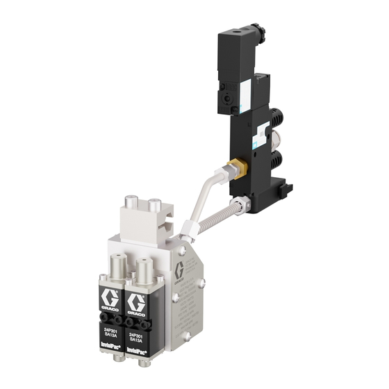
Component Identification Component Identification Dispense module Fluid outlet Fluid filter Manifold Fluid inlet (9/16–18, —6 JIC, 37° flare) Cordset Air tube Mounting clamp (1/2 in. diameter bar) Solenoid valve (24 VDC, 120 VAC); not included with all models Muffler Air inlet (3/8 in. diameter tubing) Manual override switch Solenoid valve electrical connector Figure 1 Dual Module Configuration Shown... -
Page 8: Overview
Overview Overview Grounding The valve uses the air-opened, spring closed mode of operation. It uses a three-way exhausting solenoid to control the piston inside the valve. Fluid is filtered through the manifold filter before entering the valve The equipment must be grounded to reduce the fluid inlet port. -
Page 9: Installation
Installation Installation Mounting 2. Connect the cordset (M) to the hose. 3. Connect the hose inlet to the melter system Mount manifold on a 1/2 in. (12 mm) diameter bar outlet. See the heated hose manual for using mounting clamp (H) to hold the gun assembly installation guidelines. -
Page 10: Connect Triggering Device
Installation Connect Triggering Device 5. Place the gasket on the housing and connect the electrical connector into the solenoid valve (J) with the mounting screw. See Fig. Identify if your model uses a 24 VDC or 110 VAC solenoid valve. Connect solenoid valve to 24 VDC or 110 VAC signal. -
Page 11: Install Nozzle
Operation Install Nozzle Use 1/2 in. wrench to install nozzle. See Kits and Accessories, page Operation Pressure Relief Procedure Follow the Pressure Relief Procedure Material inside the module and hose may still whenever you see this symbol. be near setpoint temperature. Wear protective clothing to avoid severe burns. -
Page 12: Maintenance
Maintenance Maintenance 2. Remove dirty filter (16) from manifold (1). Material inside the applicator can be near setpoint temperature. Wear protective clothing to avoid severe burns. Daily: Clean hot melt and char from exterior of gun. Weekly: Inspect the applicator, fluid lines, cordset, and solenoid cable for wear or damage. -
Page 13: Troubleshooting
Troubleshooting Troubleshooting Problem Cause Solution No adhesive or incorrect Plugged manifold filter Replace manifold filter. See amount of adhesive out of all Replace Inlet Filter, page modules when triggered Clogged hose Clean or replace hose. Failed solenoid valve Check for correct operation. Clean or replace. - Page 14 Troubleshooting Problem Cause Solution Gun will not heat Heater failure Check and replace heater cartridge. See Replace Heater Cartridge, page Loose cord set connection Check connection. RTD failure Check and replace RTD. See Check RTD, page Incorrect RTD for adhesive delivery Check delivery system RTD system requirement...
-
Page 15: Check Module
Troubleshooting Check Module Check Nozzle and Module Check the module operation to verify if the module Trigger the gun without the nozzle to determine if the has failed and needs to be replaced. nozzle or module is clogged. 1. Insert a small Allen wrench into the top of the 1. -
Page 16: Check Heater
Troubleshooting Check Heater Check RTD Check the continuity of the heater to verify proper Check the continuity of the RTD to verify proper resistance. If there is no continuity, the heater has resistance. If there is no continuity, the RTD has failed and needs to be replaced. -
Page 17: Repair
Repair Repair Required Tools • Phillips screw driver • Flat blade screw driver • 5/64 in (2 mm) and 5/32 in. (4 mm) Allen wrenches • 1/2 in. and 7/16 in. wrenches • Torque wrench • Waste container • High-temperature anaerobic thread sealant •... -
Page 18: Replace Heater Cartridge
Repair Replace Heater Cartridge Replace Cordset 1. Disable gun assembly. Fig 14, page 2. Use a Phillips screwdriver to remove the four Note screws (15) and manifold cover plate (18). There are two types of cordsets (17): 24P280 3. Remove the heater cartridges (3) from the is for 100 Ohm RTD controlled guns and manifold (1). - Page 19 Repair 12. Reinstall the ground lead onto the manifold (1). NOTICE Note Do not pinch any wires when inserting the terminal block in the manifold to prevent Ensure the star washer (20) is placed removing wire insulation or disconnecting below the ground ring terminal. wires.
-
Page 20: Replace Solenoid Valve
Repair Replace Solenoid Valve 1. Disable gun assembly. See Before Beginning Repair, page 2. Remove solenoid valve fitting (102) and solenoid valve (9) from tube (7). 3. Use a 1/2 in. and 7/16 in. wrench to tighten connector (102) to tube (7). Figure 16 Remove Module From Manifold 3. -
Page 21: Notes
Notes Notes 3A2805B... -
Page 22: Parts
Parts Parts Single GS35 Install heater wires in connector as shown. Torque Apply thread sealant to threads. to 5-7 in-lbs (0.5-0.8 N∙m). Apply a thin coating of lubricant to seals. Install black power lead from cordset in connector as show. Torque to 5-7 in-lbs (0.5-0.8 N∙m). Apply sealant to first 1/2 in. - Page 23 Parts Table 3 Single GS35 Quantity Part Description 24P073 24P246 24P299 24P307 - - - HOUSING, single 2 - - - MODULE, sc, hotmelt HEATER, 240 VAC, 200W, 1/2 3★ - - - dia. x 1.5 in. FERRULE, wire, 14 AWG, 4★...
- Page 24 Parts DUAL GS35 Install black power lead from cordset in connector Apply thread sealant to threads. as show. Torque to 5-7 in-lbs (0.5-0.8 N∙m). Apply a thin coating of lubricant to seals. Install white wire lead, of thermal cutoff switch, from cordset in connector as show.
- Page 25 Parts Table 4 Dual GS35 Quantity Part Description 24P074 24P075 24P076 24P247 24P300 24P301 24P302 24P308 - - - HOUSING, dual - - - 2 MODULE, sc, hotmelt HEATER, 240 VAC, 200W, - - - 3★ 1/2 dia. x 1.5 in. FERRULE, wire, 14 AWG, - - - 4★...
- Page 26 Parts Quad GS35 Install black power lead from cordset in connector Apply thread sealant to threads. as show. Torque to 5-7 in-lbs (0.5-0.8 N∙m). Apply a thin coating of lubricant to seals. Install white wire lead, of thermal cutoff switch, from cordset in connector as show.
- Page 27 Parts Table 5 Quad GS35 with 1.5 in. Spaced Manifold Quantity 24P079 24P080 24P305 24P306 24P310 Part Description - - - HOUSING, 1.5 in. 2 - - - MODULE HEATER, 240 VAC, 200W, 1/2 3★ - - - dia x 2.75 in. FERRULE, wire, 14 AWG, 4★...
- Page 28 Parts Table 6 Quad GS35 With 0.88 in. Spaced Manifold Quantity 24P077 24P078 24P250 24P254 24P303 24P304 24P309 Part Description - - - HOUSING, 0.88 in. 2 - - - MODULE HEATER, 240 VAC, 200W, 1/2 3★ - - - dia x 2.75 in.
- Page 29 Parts Solenoid Valve Kits 24P239, 24 VDC Solenoid Valve 24P240, 110 VAC Solenoid Valve Apply thread sealant to threads. Part Description Part Description - - - VALVE, solenoid, 3w, sr, 24P900 BUSHING, 1/4 npt x 1/8 24 VDC; 24P239 only npt, brass - - - VALVE, solenoid, 3w, sr,...
-
Page 30: Kits And Accessories
Kits and Accessories Kits and Accessories Module Repair Kit Mounting Clamp Kit 24P241 24P277 Part Description Includes module, mounting fasteners, and anti-size. See manual 407050. 24P276 INSULATOR, clamp, bar, housing - - - CLAMP, bar housing Solenoid Valve and Fitting Kits 108050 WASHER, lock, spring 117030... - Page 31 Kits and Accessories Blanking Plate Kit Single Heater Cartridges with Ferrules 24P810 Single heater cartridges are for custom manifolds only. Use to run two or three modules on a quad applicator or one module on a dual applicator. See manual Part Length Recommended...
-
Page 32: Dimensions
Dimensions Dimensions Applicator in. (mm) in. (mm) in. (mm) Single 2.23 (56.6) Dual 0.88 (22.4) 2.23 (56.6) Quad - 24P303 0.88 (22.4) 3.74 (95) 0.88 (22.4) Quad - 24P079 0.88 (22.4) 4.36 (111) 1.5 (38) 3A2805B... -
Page 33: Technical Data
Technical Data Technical Data InvisiPac GS35 Plug-Free Hot Melt Adhesive Applicator ™ Metric 20 million cycles Life Speed > 3,500 cycles/minute Heat up Time < 10 minutes to 350°F at 240 VAC < 10 minutes to 176°C at 240 VAC Electrical Service 200-240V, 50–60 Hz, 400W Maximum Working Fluid Pressure... -
Page 34: Graco Standard Warranty
With the exception of any special, extended, or limited warranty published by Graco, Graco will, for a period of twelve months from the date of sale, repair or replace any part of the equipment determined by Graco to be defective. This warranty applies only when the equipment is installed, operated and maintained in accordance with Graco’s written recommendations.
Need help?
Do you have a question about the InvisiPac GS35 Plug-Free and is the answer not in the manual?
Questions and answers