Sign In
Upload
Download
Table of Contents
Contents
Add to my manuals
Delete from my manuals
Share
URL of this page:
HTML Link:
Bookmark this page
Add
Manual will be automatically added to "My Manuals"
Print this page
×
Bookmark added
×
Added to my manuals
Manuals
Brands
Siemens Manuals
Control Unit
FN2006-U1
Mounting & installation
Siemens FN2006-U1 Mounting & Installation
Fiber network module (sm), fiber network module (mm)
Hide thumbs
1
2
Table Of Contents
3
4
5
6
7
8
9
10
11
12
13
14
15
16
page
of
16
Go
/
16
Contents
Table of Contents
Bookmarks
Advertisement
Table of Contents
1
Table of Contents
1
1 Fiber Network Module FN2006 / FN2007
1.1
Description
1.2
Installation
1.3
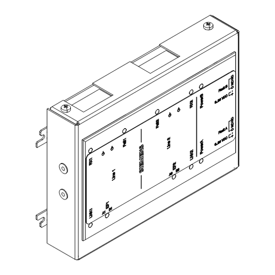
Views
1.4
Pin Assignments
1.4.1
Wiring
1.4.2
Power Supply Sockets (4, 6)
1.4.3
Sockets for Fcnet/C-WEB Circuits (7, 8)
1.5
Indicators
1.6
Technical Data
2
2 FCC Statement
Download this manual
FN2006-U1, FN2007-U1
Fiber network module (SM),
Fiber network module (MM)
Mounting
Installation
MP-UL 1.0
A6V10315048_b_en_US
01/13/2012
Siemens Industry, Inc.
Building Technologies Division
Table of
Contents
Previous
Page
Next
Page
1
2
3
4
5
Advertisement
Table of Contents
Need help?
Do you have a question about the FN2006-U1 and is the answer not in the manual?
Ask a question
Questions and answers
Related Manuals for Siemens FN2006-U1
Control Unit Siemens SAFEDLINK Mounting & Installation
Network module (12 pages)
Control Unit Siemens FN2007-U1 Mounting & Installation
Fiber network module (sm), fiber network module (mm) (16 pages)
Control Unit Siemens FN2013-U1 Installation Manual
Fiber network module (28 pages)
Control Unit Siemens SIMATIC FM 353 Manual
Stepper drive positioning module (361 pages)
Control Unit Siemens SIMATIC FM 453 Getting Started
First steps in commissioning (7 pages)
Control Unit Siemens FDCIO223 Installation Manual
Input/output module transponder (8 pages)
Control Unit Siemens FDCI223 Installation Manual
Zone module, external powered and housing (8 pages)
Control Unit Siemens FCM2041-U3 Installation Instructions Manual
(9 pages)
Control Unit Siemens SIMATIC FM 351 Installation Manual
Positioning function module (170 pages)
Control Unit Siemens FT2001-A1 Manual
Sinteso / cerberus pro mimic display driver, led ribbon cable (8 pages)
Control Unit Siemens FM 458-1 DP Manual
Function blocks (79 pages)
Control Unit Siemens SIMATIC FM 350-2 Configuring
Counter module in simatic pcs 7 (79 pages)
Control Unit Siemens FCA2018-U1 Installation Instructions Manual
Remote peripheral module (8 pages)
Control Unit Siemens FCI2011-U1 Mounting & Installation
Nac module (1a/2b) (14 pages)
Control Unit Siemens FDK:521H1134 Operating Manual
Sitrans f m magflo & sitrans f c massflo (24 pages)
Control Unit Siemens SIMADYN D FM 458 User Manual
Application module (123 pages)
This manual is also suitable for:
Fn2007-u1
Table of Contents
Print
Rename the bookmark
Delete bookmark?
Delete from my manuals?
Login
Sign In
OR
Sign in with Facebook
Sign in with Google
Upload manual
Upload from disk
Upload from URL


Need help?
Do you have a question about the FN2006-U1 and is the answer not in the manual?
Questions and answers