
Related Manuals for Chenbro RM13310


Summary of Contents for Chenbro RM13310
- Page 1 RM133 Series User Manual Rackmount Chassis November 2018 Version 1.0 A document providing an over view of product feat ures, f unct ions, archit ect ure, and suppor t specif icat ions...
- Page 2 No license (express or implied, by estoppel or otherwise) to any intellectual property rights is granted by this document. Chenbro disclaims all express and implied warranties, including without limitation, the implied warranties of merchantability, fitness for a particular purpose, and non-infringement, as well as any warranty arising from course of performance, course of dealing, or usage in trade.
-
Page 3: Table Of Contents
RM133 Series Table of Contents Table of Contents ............................... 3 List of Figures ..............................4 List of Tables ............................... 6 Product Overview ..........................7 1-1 OS Validation Levels ........................8 1-2 System Outlook Overview......................9 1-3 Front Panel ..........................11 1-4 Rear Window Overview ...................... -
Page 4: List Of Figures
RONT OVER NSTALLATION 14 R ......................19 IGURE OVER NSTALLATION 15 RM13304 HDD C ..................... 20 IGURE NSTALLATION 16 RM13310 HDD C ..................... 20 IGURE NSTALLATION 17 3.5” H HDD A ..................21 IGURE SWAP SSEMBLY NSTALLATION 18 3.5” H HDD A ..................... - Page 5 RM133 Series 38 A ........................33 IGURE AFFLE NSTALLATION 39 PCI- ........................ 34 IGURE LANK EMOVAL 40 PCI- ........................34 IGURE NSTALLATION 41 1U S PSU I ....................... 35 IGURE INGLE NSTALLATION 42 1U S PSU I ....................... 35 IGURE INGLE NSTALLATION 43 1U RPSU M...
-
Page 6: List Of Tables
RM133 Series List of Tables RM13304/10 S ....................7 ABLE HENBRO PECIFICATIONS RM133 S ......................13 ABLE ERIES YSTEM VERVIEW ......................... 15 ABLE LIDE RAIL NSTALLATION ....................16 ABLE YSTEM NVIRONMENTAL IMITS UMMARY ..........................17 ABLE YST EM ACKAGING RM13304/10 W ..................... -
Page 7: Product Overview
1. Product Overview This chapter provides a high-level overview of the system features and available options. More details for each major sub-system, feature, or options are provided in the following chapters. Table 1 Chenbro RM13304/10 Specifications Feature Description M/B Form Factor EEB(12’’x13’’)/ ATX (12’’x9.6’’) -
Page 8: Os Validation Levels
Vendors will not be required by Chenbro to develop drivers for operating systems that they do not already support. Chenbro will NOT provide support for issues related to the use of any add-in adapters or peripherals installed in the server system when an operating system that received only basic installation testing is in use. -
Page 9: System Outlook Overview
RM133 Series 1-2 System Outlook Overview Figure 1 RM13304 Outlook Over view Figure 2 RM13310 Outlook Over view / Product Overview │... -
Page 10: Figure 3 Rm13304 Major Components Overview
RM133 Series Figure 3 RM13304 Major Components Over view Figure 4 RM13310 Major Components Over view A. Front Top Cover D. Top Cover Latch G. Fan Assembly B. Back Top Cover E. Optical Drive Bay H. Server Board C. Label Emboss F. -
Page 11: Front Panel
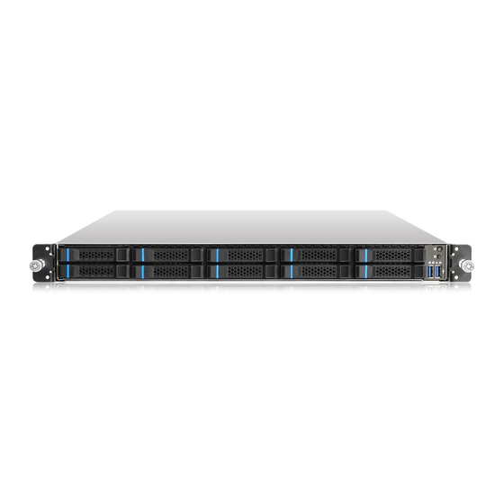
RM133 Series 1-3 Front Panel Figure 5 RM13304 3.5’’ Drive Bay-4 Figure 6 RM13310 2.5” Drive Bay-10 A. Rack Handles C. Optical Drive Bay E. Front Control Panel B. Storage Drive Bay D. Info Tag F. Storage Drive Bay / Product Overview │... -
Page 12: Rear Window Overview
RM133 Series 1-4 Rear Window Overview Figure 7 Rear Window Overview (RPSU) Figure 8 Rear Window Overview (Single PSU) A. 1U Redundant Power Supply C. I/O Ports B. Single Power Supply D. Full Height Expansion Slot / Product Overview │... -
Page 13: Front Control Panel Overview
RM133 Series 1-5 Front Control Panel Overview Figure 9 Front Control Panel Figure 10 Front Control Panel Table 2 RM133 Series System Overview Label ICON Overview Power Button LAN1,LAN2 Activity LED Power LED HDD Activity LED System Alarm LED USB 3.0 UID Button/LED Rack Handle (Screw Type) Rack Handle (Latch Type) -
Page 14: System Dimensions
RM133 Series 1-6 System Dimensions Figure 11 Chassis Dimensions Figure 12 Label Emboss Dimensions / Product Overview │... -
Page 15: Available Rack Mounting Kit Options (Refer To "Installation")
Advisory Note – Available rack and cabinet mounting kits are not designed to support shipment of the server system while installed in a rack. If you chose to do so, Chenbro advises you verify your shipping configuration with appropriate shock and vibration testing, before shipment. -
Page 16: System Level Environmental Limits
RM133 Series 1-8 System Level Environmental Limits The following table defines the system level operating and non-operating environmental limits. Table 4 System Environmental Limits Summary Parameter Limits *Range may vary, refer to Technical Product Specification* Temperature Non-Operating -40º C to 70º C (-40º F to 158º F) Humidity Non-Operating 50% to 90%, non-condensing with a maximum wet bulb of 28°... -
Page 17: System Packaging
1-9 System Packaging The original Chenbro packaging, in which the server system is delivered, is designed to provide protection to a fully configured system and was tested to meet ISTA (International Safe Transit Association) Test Procedure 1A (2008). The packaging was also designed to be re-used for shipment after system integration has been completed. -
Page 18: Installation
Up to 4 x 3.5” hot swap SAS / SATA HDD (RM13304) Up to 10 x 2.5” hot swap SAS / SATA HDD or SSD (RM13310) 2 x 2.5’’ internal HDD or SSD up to 9.5mm thickness (RM13304) ... -
Page 19: Top Cover Installation
RM133 Series 2-1 Top Cover Installation Figure 13 Front Top Cover Installation 1. Insert the front top cover, and ensure the alignment holes match up on both side. 2. Secure front top cover with two screws as shown. Figure 14 Rear Top Cover Installation 1. -
Page 20: Hdd Cage Installation
1. Insert HDD cage and carefully align the tabs of the cage with the slots on the chassis 2. Secure HDD cage with two screws as shown. Figure 16 RM13310 HDD Cage Installation 1. Insert HDD cage and carefully align the tabs of the cage with the slots on the chassis 2. -
Page 21: External Hot-Swap Hdd Tray Instruction
RM133 Series 2-3 External Hot-swap HDD Tray Instruction Figure 17 3.5” Hot-swap HDD Assembly Installation 1. With the lever open, insert the HDD assembly into the chassis opening and push until the locking lever engaged. 2. Push in the lever to lock it into place. Figure 18 3.5”... -
Page 22: Figure 19 3.5" Hdd Installation (Tool-Less)
RM133 Series Figure 19 3.5” HDD Installation (Tool-less) 1. Align front HDD with the anchor point on the tray. 2. Slide in HDD at an angle and push down carefully. NOTE: Due to degraded performance and reliability concerns, the use of the 3.5” drive blank as a 2.5” device bracket is intended to support SSD type storage devices only. -
Page 23: Figure 21 2.5" Hdd Installation (Screw)
RM133 Series Figure 21 2.5” HDD Installation (Screw) 1. Align front HDD with the anchor point on the tray. 2. Assemble 2.5” SSD into tray by 3 screws on the tray bottom. / Installation │... -
Page 24: Figure 22 2.5'' Hot-Swap Hdd Assembly Installation
RM133 Series Figure 22 2.5’’ Hot-swap HDD Assembly installation 1. With the lever open, insert the HDD assembly into the chassis opening and push until the locking lever engaged. 2. Push in the lever to lock it into place. Figure 23 2.5’’ Hot-swap HDD Assembly Removal 1. -
Page 25: Figure 24 2.5'' Hdd Installation (Tool-Less)
RM133 Series Figure 24 2.5’’ HDD Installation (Tool-less) 1. Align front HDD with the anchor point on the tray and slide in HDD at an angle. 2. Push down HDD carefully. NOTE: To ensure proper system air flow requirements, all front drive bays must be populated with a drive carrier. Drive carriers must be installed with either a drive or supplied drive blank. -
Page 26: Internal 2.5'' Hdd Installation
RM133 Series 2-4 Internal 2.5’’ HDD Installation Figure 26 RM13304 Internal 2.5'' HDD Installation 1. Attach the plastic carrier with HDD and engage both embossed pins into the side dimples on the HDD as shown. 2. Insert the 2.5” HDD assembly into the Chassis. 3. -
Page 27: Internal Slim Odd Installation
RM133 Series 2-5 Internal Slim ODD Installation Figure 27 Internal Slim ODD Installation 1. Insert the slim ODD with an angle as shown. Ensure that two embossed pin and side dimples engaged. 2. Carefully push down the slim ODD until it stays into place. / Installation │... -
Page 28: Rack Handle For System Maintenance
RM133 Series 2-6 Rack Handle for System Maintenance Figure 28 Rack Handle Location (Screw Type) 1. Push the system all the way into the cabinet. 2. Secure the system with thumb screw on both sides as shown. Figure 29 Rack Handle Location (Latch Type) 1. -
Page 29: Fan Module Installation
RM133 Series 2-7 Fan Module Installation Figure 30 Fan Assembly Installation (4028) 1. Attach the fan guard with fan as shown and secure it with two screws. 2. Insert four fan mounts as shown. Figure 31 Fan Module Installation (4028) 1. -
Page 30: Figure 32 Fan Assembly Installation (4048)
RM133 Series Figure 32 Fan Assembly Installation (4048) 1. Attach the fan guard with fan as shown and secure it with two screws. 2. Attach plastic extension holder with fan. 3. Insert four fan mounts as shown. Figure 33 Fan Module Installation (4048) 1. -
Page 31: Figure 34 Fan Assembly Installation (4056)
RM133 Series Figure 34 Fan Assembly Installation (4056) 1. Attach the fan guard with fan as shown and secure it with two screws. 2. Attach plastic extension holder with fan. 3. Insert four fan mounts as shown. Figure 35 Fan Module Installation (4056) 1. -
Page 32: Figure 36 Fan Assembly Installation (4056)
RM133 Series Figure 36 Fan Assembly Installation (4056) 1. Attach the fan guard with fan as shown and secure it with two screws. 2. Insert four fan mounts as shown. Figure 37 Fan Module Installation (4056) 1. Attach the fan bracket with chassis bottom as shown and secure it with four screws. 2. - Page 33 RM133 Series Figure 38 Air Baffle Installation 1. Insert the air baffle into the securing slots until the tabs lock into place. / Installation │...
-
Page 34: Pci-E Card Installation
RM133 Series 2-8 PCI-e Card Installation Figure 39 PCI-e Card Blank Removal Remove the PCI-e blank. Secure the riser card with PCI-e bracket with two screws. Secure the PCI-e card with filler with two screws. Firmly press the PCI-e card into the riser slot. Firmly press the PCI-e riser securing into the M/B expansion slot. -
Page 35: Psu Installation
RM133 Series 2-9 PSU Installation PSU Installation Figure 41 1U Single PSU Installation Figure 42 1U Single 1. Secure the PSU bracket with two screws as shown. 2. Secure the PSU (bracket) with two screws on the bottom of chassis. 3. - Page 36 RM133 Series 1U RPSU Module Installation Figure 43 1. Insert the PSU module into the PSU cage and push until it clicked into place. 1U RPSU Module Removal Figure 44 1. Press and release latch as shown. 2. Carefully pull the PSU out of the chassis. / Installation │...
-
Page 37: Slide Rail Installation
RM133 Series 2-10 Slide Rail Installation Figure 45 Slide rail Installation (84H314610-003) 1. Attach the inner rail with the system while aligning the back shoulder screws on the side of the system with the back slots on the inner rail. Figure 46 Slide rail Installation (84H314610-003) 2. - Page 38 RM133 Series Figure 47 Slide rail Installation (84H314610-003) 3. Move the latch upward while securing the screw. 4. Secure the inner rail with one screw. Figure 48 Slide rail Installation (84H314610-003) 5. Carefully install the system into the rack with two hands. / Installation │...
-
Page 39: Backplane
RM133 Series 3. Backplane Each drive carrier includes separate LED indicators for drive Activity and drive Status. Light pipes integrated into the drive carrier assembly direct light emitted from LEDs mounted next to each drive connector on the backplane to the drive carrier faceplate, making them visible from the front of the system. -
Page 40: Storage Backplane Optional
RM133 Series 3-1 Storage Backplane Optional RM133 support below backplane. 4 x 3.5” SATA 7-pin port to port passive backplane 10 x 2.5” Mini SAS HD passive backplane 10x 2.5” NVMe passive backplane All available SAS/SATA/NVMe compatible backplanes include the following common features: 12Gb/s SAS, 6Gb/s SAS/SATA, and PCIe Gen3 x4 NVMe ... -
Page 41: 3.5" 4 Port Passive Backplane
RM133 Series 3-2 12G 3.5” 4 Port Passive Backplane Table 8 12G 3.5” 4 Port Passive Backplane Specification Host Interface SATA 7-pin HDD Interface SAS / SATA Hot-Swap Yes, allows user to on line replace Hard Disk Drive Display LED indicates Hard Disk Drive status Power LED –... - Page 42 RM133 Series Figure 51 12G 3.5” 4 Port Passive Backplane – rear view Table 9 Label Description Drawing Label Description Description Power connector backplane includes connector supplying power to the backplane. Power is routed to the backplane via a power cable harness from the Power Supply Modules.
-
Page 43: 2.5" 10 Port Passive Backplane
RM133 Series 3-3 12G 2.5” 10 Port Passive Backplane Table 10 12G 2.5” 10 Port Passive Backplane Specification Host Interface Mini SAS HD HDD Interface SAS / SATA Hot-Swap Yes, allows user to on line replace Hard Disk Drive Display LED indicates Hard Disk Drive status Power LED –... - Page 44 RM133 Series On the backside of the backplane are several connectors. The following illustration identifies each. Figure 53 12G 2.5” 10 Port Passive Backplane – rear view Table 11 Label Description Drawing Label Description Description Power connector The backplane includes a 2x2 connector supplying power to the backplane.
-
Page 45: Nvme 2.5" 10 Port Passive Backplane
RM133 Series 3.4 NVMe 2.5” 10 Port Passive Backplane Table 12 NVMe 2.5” 10 Port Passive Backplane Specification Host Interface OCuLink HDD Interface NVMe Hot-Swap Yes, allows user to on line replace Hard Disk Drive Display LED indicates Hard Disk Drive status Power LED –... - Page 46 RM133 Series On the backside of the backplane are several connectors. The following illustration identifies each. Figure 55 12G Mini SAS HD 8 Port passive Backplane – rear view Table 13 Label Description Drawing Label Description Description Power connector The backplane includes a 2x2 connector supplying power to the backplane.
-
Page 47: Maintenance And Service
You may need to return the defective item by request. The customer should ensure that the products are Defect On Arrival for up to three months from Chenbro’s shipping date and the damage is not caused by shipping or failures resulting from accident, misuse, abuse, neglect, mishandling, misapplication, modification, improper operation, improper repair or rework.
Need help?
Do you have a question about the RM13310 and is the answer not in the manual?
Questions and answers