Table of Contents
Advertisement
Advertisement
Table of Contents

Related Manuals for Chenbro RM312


Summary of Contents for Chenbro RM312
- Page 1 RM312 Rackmount Chassis User Guide Rev. 01...
-
Page 2: Table Of Contents
LED BOARD....................20 ..................... 20 EATURES LED B ..................21 OARD AYOUT ................... 22 SSIGNMENTS APPENDIX A ....................24 ................... 24 PTIONAL ABLES APPENDIX B ....................25 ................25 OWER PTIONS NOTICES......................26 CONTACT INFORMATION ................27 ....................27 EADQUARTERS RM312 User Guide 19" Rackmount Chassis... -
Page 3: Your Rackmount Chassis
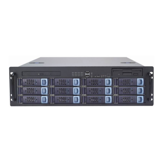
ACKMOUNT HASSIS The RM312 19" rackmount chassis supports a variety of high-density system configurations and features the latest in server-chassis technology. Features Top Cover Ø Screw-less design for easy installation and maintenance Ø Quick reference guide affixed to the inside Front Panel Controls and Indicators Ø... -
Page 4: Specifications
2 × 60mm rear fans Slot Opening Material SGCC Sheet Metal Thickness 1.2mm Net Weight (chassis only) 15.1kg Cubic Feet 5.27 20’ 176 units Reference Container Load (single packing) 40’ 368 units Backplane IDE/SCSI/SATA RM312 User Guide 19" Rackmount Chassis... -
Page 5: Layout
A. HDD Tray Activity LEDs (1-12) F. Failure LED B. USB2.0 Port x2 G. System HDD Activity LED C. LAN1 and LAN2 LEDs H. Power LED D. Alarm Mute Button Power Switch E. System Reset Button RM312 User Guide 19" Rackmount Chassis... -
Page 6: Back Panel
Back Panel Two 60mm Exhaust Fans (optional) Single or n+1 System I/O Ports Seven PCI Slots Redundant (M/B dependent) Power Supply (optional) RM312 User Guide 19" Rackmount Chassis... -
Page 7: Installation
NSTALLATION For your safety When deciding on a location for your RM312 rackmount chassis, please take the following into consideration: Electric Power: The power cord is what powers on/off your chassis, so try to place the chassis near a power outlet for convenience. Next, be aware of RM312's power rating to avoid overloading its circuits. -
Page 8: Parts List
Parts List • RM312 Rackmount Chassis (P/N: 90-331200-001) • Accessory Box (P/N: 84-331210-001) - CD-ROM Adapter (P/N: 80-091801-011) - Screws and Spacers: ACKET CREW NSTALLATION EVICE MAGE EQUIRED Phillips Screwdriver HDD Tray 70-000000-149 Phillips Screwdriver Internal HDD 70-000000-149 Phillips Screwdriver... - Page 9 Big 4P to big 26-113215-003 4P+250mm big 4P • Optional Items: - 26” General Device Rack Rail Kit - 60mm Rear Exhaust Fans x 2 - Power Cord (refer to Appendix B for plug options) RM312 User Guide 19" Rackmount Chassis...
-
Page 10: Installing Hard Disk Drives (Hdd)
2. Attach the HDD to the bracket with four additional screws from the included HDD screw packet (P/N: 70-000000-149). 3. Slide the bracket forward, following the three guide pins, until it fits into place. 4. Reattach the original screw. RM312 User Guide 19" Rackmount Chassis... -
Page 11: Installing Afdd
3. Attach the slim CD/DVD-ROM onto the bracket with four additional screws from the included CD-ROM screw packet (P/N:70-331900-101). 4. Slide the bracket forward, following the two guide pins, until it fits into place 5. Reattach the securing screw. RM312 User Guide 19" Rackmount Chassis... -
Page 12: Changing The 80Mm System Fans
4. Remove the four screws to take out the finger guard. 5. Replace the faulty fan with a new one. 6. Reassemble, then place back into the fan bracket and reconnect to the backplane. RM312 User Guide 19" Rackmount Chassis... -
Page 13: Installing The Backplane (Optional Item)
Installing the Backplane (optional item) RM312 supports the following three different backplanes: SCSI, IDE, and SATA. SCSI Backplane Assembly IDE Backplane Assembly SATA Backplane Assembly RM312 User Guide 19" Rackmount Chassis... - Page 14 7. Now connect the Big 4p power cable from the PSU to the power connectors (J7 and J8) on the SCSI backplane. 8. Connect the fan connector to the fan pin header of the upper backplane to finish the installation, and check to see the fan sensor is enabled. RM312 User Guide 19" Rackmount Chassis...
-
Page 15: Installing A Motherboard (Optional Part)
Installing the Power Supply Unit (optional device) 1. Place the power supply unit (PSU) into in the area shown and secure it with four screws. 2. With another two screws, secure it to the other side of the chassis. RM312 User Guide 19" Rackmount Chassis... -
Page 16: Installing The General Rack Rail Kit (Optional Part)
Do this for both the left and right side rail assemblies. 2. Now position the same inner fixed chassis rail along the side of the RM312 chassis. Making sure the holes line up, screw the rail securely to the side of the chassis. -
Page 17: Installing The Bezel
2. Next, install the bezel supports and tighten screws securely. 3. Then fit the right side of bezel to its corresponding support and snap into place. RM312 User Guide 19" Rackmount Chassis... -
Page 18: Backplane Board
Ø 2pcs power connectors in big 4-pin, right angle, D-type Ø Power On LED Ø 4 external LEDs monitoring for HDD installation, HDD access, and fan overheating fail and buzzer mute connector pin RM312 User Guide 19" Rackmount Chassis... -
Page 19: Backplane Layout
Backplane Layout Dimensions: 411.60*51.44*2.4mm FAN1 FAN2 FAN3 FAN4 FAN5 RM312 User Guide 19" Rackmount Chassis... -
Page 20: Pin Assignments
Position1 Position2 Position3 Position4 Ø Avoid setting SCSI ID 7 for SCSI drive. It normally hosts the SCSI host adapter. Ø The default setting for SCSI drives are from ID0, ID1, ID2, and ID3. RM312 User Guide 19" Rackmount Chassis... - Page 21 Pin 11 Buzzer Mute Switch + Pin 12 Buzzer Mute Switch - Fan 1, Fan 2, Fan 3, Fan 4, Fan 5: Connector Pin Assignments Description SENSOR J7 and J8: Big 4P Pin Assignments Description RM312 User Guide 19" Rackmount Chassis...
-
Page 22: Led Board
Ø 1 fails red LED indicator Ø 2 USB port Ø 2 LAN LED indicator Ø 4 connectors for 1U, 2U, 3U, 4U LED boards Ø 2 x 10 pin connectors for USB port Ø 1 system connector RM312 User Guide 19" Rackmount Chassis... -
Page 23: Led Board Layout
Description 1U LED LED1 HDD1 2U LED LED2 HDD2 3U LED LED3 HDD3 4U LED LED4 HDD4 System LED5 LAN Activity Alarm Mute SW LED6-1 Fail System Reset SW LED6-2 Power SW LED6-3 Power RM312 User Guide 19" Rackmount Chassis... -
Page 24: Pin Assignments
LED23 + LED24 + +5V VCC Fail Mute None J3: 3U LED Board Pin Outs Pin # Description Pin # Description LED31 + LED32 + LED33 + LED34 + +5V VCC Fail Mute None RM312 User Guide 19" Rackmount Chassis... - Page 25 Pin # Description Reset Reset GND Power Switch Power Switch GND Power LED + Power LED - HDD LED + HDD LED - LAN1 LED + LAN2 LED - LAN2 LED + LAN2 LED - RM312 User Guide 19" Rackmount Chassis...
-
Page 26: Optional Cables
ABLE PPEARANCE Intel Spec 750mm 26-033219-001 Universal Spec 750mm 26-033219-002 IDE: ENGTH ABLE PPEARANCE ATA-133 IDE 700mm 26-073215-001 ATA-133 IDE 560mm 26-073118-006 SATA: ENGTH ABLE PPEARANCE Serial ATA 700mm 26-123215-001 Serial ATA 560mm 26-123215-002 RM312 User Guide 19" Rackmount Chassis... -
Page 27: Power Cord Plug Options
PPENDIX Power Cord Plug Options OUNTRY EGION ONNECTOR Europe 34-032100-001 Greece 34-073100-002 Italy 34-023100-001 Japan 34-013100-002 South Africa 34-083100-001 Taiwan 34-013100-001 34-043100-002 RM312 User Guide 19" Rackmount Chassis... -
Page 28: Notices
© 2003 Chenbro Micom Co., Ltd. All rights reserved Chenbro Micom Co., Ltd. reserves the right to make improvements to the products described in this manual at any time. Specifications and features are subject to change without prior notice. No part of this manual may be reproduced, copied, translated, or transmitted in any form or by any means without the prior written permission of Chenbro Micom Co., Ltd. -
Page 29: Contact Information
ONTACT NFORMATION Headquarters CHENBRO MICOM CO., LTD. 150 Jian Yi Road, 15F Chung Ho City 235, Taipei County Taiwan Tel: +886 (2) 8226-5500 Fax: +886 (2) 8226-5423 E-mail: info@chenbro.com.tw Website: www.chenbro.com.tw CHENBRO MICOM (USA) INC. CHENBRO UK 2260 S. Haven Ave., Unit E...
Need help?
Do you have a question about the RM312 and is the answer not in the manual?
Questions and answers