
Related Manuals for Chenbro RM238 Series


Summary of Contents for Chenbro RM238 Series
- Page 1 RM238 Series Rackmount Chassis User Manual January 2020 Version 1.1 A document provides an overview of product features, functions, architecture, and support specifications.
- Page 2 No license (express or implied, by estoppel or otherwise) to any intellectual property rights is granted by this document. Chenbro disclaims all express and implied warranties, including without limitation, the implied warranties of merchantability, fitness for a particular purpose, and non-infringement, as well as any warranty arising from course of performance, course of dealing, or usage in trade.
-
Page 3: Table Of Contents
Table of Contents List of Figures ..............................4 List of Tables ..............................7 Product Overview ......................... 8 1-1 System Features Overview....................... 9 1-2 Front Panel ..........................11 1-3 Back Panel ..........................12 1-4 Front Control Panel ....................... 13 1-5 Storage Configurations ......................14 1-6 Chassis Dimensions ....................... -
Page 4: List Of Figures
RM238 Series List of Figures Figure 1 RM23808 overview ........................9 Figure 2 RM23812 overview ........................9 Figure 3 RM23824 overview ........................9 Figure 4 RM23808 major components overview..................10 Figure 5 RM23812 major components overview..................10 Figure 6 RM23824 major components overview..................10 Figure 7 RM23808 front panel ....................... - Page 5 RM238 Series Figure 39 2.5” HDD installation (screw type) .................... 29 Figure 40 2.5’’ HDD removal in 3.5” tray (screw type) ................30 Figure 41 2.5’’ HDD installation in 3.5” tray (screw type) ................30 Figure 42 Internal 2.5'' HDD removal (RM23808) ..................31 Figure 43 RM23808 internal 2.5'' HDD installation ...................
- Page 6 Figure 78 Backplane front view ........................ 59 Figure 79 Backplane rear view ......................... 60 Figure 80 Backplane front view ........................ 61 Figure 81 Backplane rear view ......................... 62 Figure 82 Backplane front view ........................ 63 Figure 83 Backplane rear view ......................... 64 Figure 84 Expander board rear view......................
-
Page 7: List Of Tables
RM238 Series List of Tables Table 1 Chenbro RM23808/12/24 specifications ..................8 Table 2 Front control panel ........................13 Table 3 Slide rail options ........................17 Table 4 System environmental specifications summary ................18 Table 5 System packaging information ....................19 Table 6 Product weight information ....................... -
Page 8: Product Overview
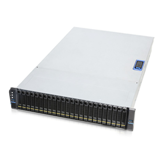
RM238 Series 1. Product Overview RM238 series offers a variety of system options to meet the various configuration requirements of high-density/high-performance computing environments. This 2U chassis supports both 2.5” and 3.5” storage form factors with different drive bay configurations. This chapter provides a high-level overview of the system features and available options. More details for each major sub-systme, feature, or option are provided in the following chapters. -
Page 9: System Features Overview
RM238 Series 1-1 System Features Overview Figure 1 RM23808 over view Figure 2 RM23812 over view Figure 3 RM23824 over view Product Overview│ 9... -
Page 10: Figure 4 Rm23808 Major Components Overview
RM238 Series Figure 4 RM23808 major components over view Figure 5 RM23812 major components over view Figure 6 RM23824 major components over view A. Front Top Cover E. Internal 2.5” HDD Bays I. 2.5” HDD Hot-swap Cage B. Rear Top Cover F. -
Page 11: Front Panel
RM238 Series 1-2 Front Panel Figure 7 RM23808 front panel Figure 8 RM23812 front panel Figure 9 RM23824 front panel A. Front Control Panel C. Info Tag E. Slim ODD Bay B. Storage Drive Bay D. Rack Handles Product Overview│ 11... -
Page 12: Back Panel
RM238 Series 1-3 Back Panel Figure 10 Back panel with single PSU Figure 11 Back panel with redundant PSU A. 2U Single Power Supply D. Low Profile Expansion Slots B. CRPS E. 2.5” Hot-swap Drive Bay C. I/O Gasket Product Overview│ 12... -
Page 13: Front Control Panel
RM238 Series 1-4 Front Control Panel Figure 12 Front control panel Table 2 Front control panel Label ICON Indicator, button or connector Power Button UID Button Reset Button USB3.0 HDD Activity LED System Alarm LED LAN1, LAN2 Activity LED Rack Handle (Left) -
Page 14: Storage Configurations
RM238 Series 1-5 Storage Configurations Figure 13 8 x 3.5” front drive bay configuration Figure 14 12 x 3.5” front drive bay configuration Figure 15 24 x 2.5” front drive bay configuration (24 x SATA/SAS) Product Overview │... -
Page 15: Figure 16 24 X 2.5" Front Drive Bay Configuration (4 X Nvme + 20 X Sata/Sas)
RM238 Series Figure 16 24 x 2.5” front drive bay configuration (4 x NVMe + 20 x SATA/SAS) Figure 17 24 x 2.5” front drive bay configuration (8 x NVMe + 16 x SATA/SAS) Figure 18 24 x 2.5” front drive bay configuration (20 x NVMe + 4 x SATA/SAS) Figure 19 24 x 2.5”... -
Page 16: Chassis Dimensions
RM238 Series 1-6 Chassis Dimensions Figure 20 Chassis dimensions Figure 21 Label embossing dimensions Product Overview │... -
Page 17: Available Rack Mounting Kit Options (Refer To "Installation")
Advisory Note – Available rack and cabinet mounting kits are not designed to support shipment of the server system while installed in a rack. If you chose to do so, Chenbro advises you to verify your shipping configuration with appropriate shock and vibration testing before shipment. -
Page 18: System Level Environmental Specifications
RM238 Series 1-8 System Level Environmental Specifications The following table defines the system level specifications under operating and non-operating environments. Table 4 System environmental specifications summary Parameter Specification Temperature Operating 5º C to 35º C (41º F to 95º F) -
Page 19: System Packaging
1-9 System Packaging The original Chenbro packaging, where the server system is delivered, is designed to provide protection for L5 configuration and tested to meet ISTA (International Safe Transit Association) Test Procedure 1A (2008). The packaging is also designed to be reused for shipment after the system integration has been completed. -
Page 20: System Components Removal And Installation
RM238 Series 2. System Components Removal and Installation RM238 series supports a variety of different storage options: Up to 8 x 3.5” hot-swap HDD or 2.5” HDD/SSD (RM23808) Up to 12 x 3.5” hot-swap HDD or 2.5” HDD/SSD (RM23812) ... -
Page 21: Top Cover Removal And Installation
RM238 Series 2-1 Top Cover Removal and Installation Figure 22 Rear top cover removal 1. Loosen two screws on the rear top cover. 2. Pull the latch as shown to release the cover. 3. Remove the cover. Figure 23 Front top cover removal 1. -
Page 22: Figure 24 Front Top Cover Installation
RM238 Series Figure 24 Front top cover installation 1. Align the guide pins of the cover with the grooves on the chassis base. (Three guide pins for both sides) 2. Slide the cover toward the front panel until it is locked into place. -
Page 23: Hdd Cage Removal And Installation
RM238 Series 2-2 HDD Cage Removal and Installation Figure 26 HDD cage removal 1. Loosen the two screws of the chassis base as shown. 2. Pull the HDD cage toward the front panel until it unlocks. 3. Remove the HDD cage vertically. -
Page 24: Hot-Swap Hdd Assembly Removal And Installation
RM238 Series 2-3 Hot-swap HDD Assembly Removal and Installation Figure 28 3.5” hot-swap HDD assembly removal 1. Press the tray button to release the lever as shown. 2. Pull the HDD assembly out of the drive bay. Figure 29 3.5” hot-swap HDD assembly installation 1. -
Page 25: Figure 30 3.5" Hdd Removal (Tool-Less Type)
RM238 Series Figure 30 3.5” HDD removal (tool-less type) 1. Bottom up the HDD assembly, and loosen the screw as shown. 2. Press out the HDD by your two thumbs. NOTE: Please operate this on a stable surface in case the HDD dropping unexpectedly. -
Page 26: Figure 32 3.5" Hdd Removal (Screw Type)
RM238 Series Figure 32 3.5" HDD removal (screw type) 1. Loosen four screws as shown. 2. Take out the HDD from the tray. Figure 33 3.5" HDD installation (screw type) 1. Align the HDD with the anchor point on the tray. -
Page 27: Figure 34 2.5" Hot-Swap Hdd Assembly Removal
RM238 Series Figure 34 2.5" hot-swap HDD assembly removal 1. Press the tray button, and release the lever as shown. 2. Pull the HDD assembly out of the drive bay. Figure 35 2.5’’ hot-swap HDD assembly installation 1. With the lever open, insert the HDD assembly into the drive bay until the end of the HDD cage. -
Page 28: Figure 36 2.5'' Hdd Removal (Tool-Less Type)
RM238 Series Figure 36 2.5’’ HDD removal (tool-less type) 1. Bottom up the HDD assembly, and face the side without a concave slot of the HDD tray as shown. 2. Press out the HDD by your two thumbs. NOTE: Please operate this on a stable surface in case the HDD dropping unexpectedly. -
Page 29: Figure 38 2.5" Hdd Removal (Screw Type)
RM238 Series Figure 38 2.5" HDD removal (screw type) 1. Loosen four screws as shown. 2. Take out the HDD from the tray. Figure 39 2.5” HDD installation (screw type) 1. Align the front of the HDD with the anchor points on the tray. -
Page 30: Figure 40 2.5'' Hdd Removal In 3.5" Tray (Screw Type)
3.5” drive, a 2.5” drive with plastic dummy filler or only dummy fillers. In addition, in order to support a 2.5” drive in a 3.5” tray, a screw-type tray is required. NOTE: Dedicated screw type is required for 2.5” SSD Installation, Chenbro P/N: 384-14602-3143A0. System Components Removal and Installation... -
Page 31: Internal 2.5'' Hdd Removal And Installation
RM238 Series 2-4 Internal 2.5’’ HDD Removal and Installation Figure 42 Internal 2.5'' HDD removal (RM23808) 1. Lift the plastic bracket tab to release HDD assembly as shown. 2. Remove it from the HDD cage. 3. Detach the plastic bracket from HDD. -
Page 32: Slim Odd Removal And Installation
RM238 Series 2-5 Slim ODD Removal and Installation Figure 44 RM23808 slim ODD removal 1. Press the latch to release the ODD assembly. 2. Pull it out of the cage. 3. Loosen the two screws to detach the plastic bracket. -
Page 33: System Maintenance
RM238 Series 2-6 System Maintenance Figure 46 Removal of whole system from the rack 1. Open and hold the latches on both sides as shown. 2. Loosen the screws in the latches, and firmly grab the rack handles on both sides. -
Page 34: Fan Assembly Removal And Installation
RM238 Series 2-7 Fan Assembly Removal and Installation Figure 48 Fan assembly removal 1. Loosen the thumb screws on both sides of the fan assembly. 2. Disconnect all the fan connectors. 3. Remove the fan assembly from the chassis base. -
Page 35: Figure 50 Fan Module Removal
RM238 Series Figure 50 Fan module removal 1. Press the latch as shown and release the fan module from the fan cage vertically. Figure 51 Fan module installation 1. Insert the fan module into the fan cage until it is secured into place. -
Page 36: Figure 52 Air Baffle Removal
RM238 Series Figure 52 Air baffle removal 1. Pull out the air baffle from the fan cage. Figure 53 Air baffle installation 1. Insert the air baffle into the fan cage until it is secured into place. System Components Removal and Installation... -
Page 37: 2-Bay Drive Cage Installation (Back Panel)
RM238 Series 2-8 2.5" 2-bay Drive Cage Installation (Back Panel) Figure 54 Drive cage bracket installation (back panel) 1. Attach the drive cage bracket on the bottom of the chassis, and ensure the alignment of screw holes matched. 2. Secure the bracket with two screws from the outside to the inside of the chassis. -
Page 38: Figure 56 Drive Backplane Installation (Back Panel)
RM238 Series Figure 56 Drive backplane installation (back panel) 1. Attach the backplane to the rear of the drive cage as shown. 2. Ensure the backplane firmly engaged with the cage. 3. Secure the backplane with one screw. System Components Removal and Installation... -
Page 39: Full-Height Pcie Card Installation
RM238 Series 2-9 Full-height PCIe Card Installation Figure 57 Full-height back panel bracket installation 1. Replace the low-profile back panel bracket with the full-height one. 2. Secure the bracket with two screws as shown. Figure 58 Cards and brackets installation 3. -
Page 40: Psu Installation And Removal
RM238 Series 2-10 PSU Installation and Removal Figure 59 Single 2U PSU installation 1. Install the PSU into the chassis, and ensure the alignment of screw holes on the PSU, the chassis base and the back panel matched. 2. Secure the PSU with the back panel by three screws. -
Page 41: Figure 60 Redundant Psu Cage Assembly
RM238 Series Figure 60 Redundant PSU cage assembly 1. Attach the PSU side bracket to the PSU cage, and secure it by two screws from the inside of the cage as shown. 2. Attach the PSU front bracket to the PSU cage, and secure it by two screws. -
Page 42: Figure 62 Crps Module Installation
RM238 Series CRPS module installation Figure 62 1. Insert CRPS module into the PSU cage and push until it is secured into place. CRPS module removal Figure 63 1. Press the latch without release as shown. 2. Pull the module handle to remove it from the PSU cage. -
Page 43: Slide Rail Installation
RM238 Series 2-11 Slide Rail Installation Figure 64 Slide rail installation-1 (384-23803-3300B0) 1. Attach the inner rail to the chassis base while aligning the T pins on the side of the system with the slots on the inner rail. Figure 65 Slide rail installation-2 (384-23803-3300B0) 2. -
Page 44: Figure 66 Slide Rail Installation-3 (384-23803-3300B0)
RM238 Series Figure 66 Slide rail installation-3 (384-23803-3300B0) 3. Lift the latch as shown. 4. Secure the inner rail with one screw. Figure 67 Slide rail Installation-4 (384-23803-3300B0) 5. Install the system into the rack. System Components Removal and Installation... -
Page 45: Backplane
RM238 Series 3. Backplane Each drive tray includes two LED indicators for drive activity and drive status. Light pipes integrated into the drive tray direct light emitted from LEDs mounted next to each drive connector on the backplane to the drive tray faceplate, making them visible from the front of the system. -
Page 46: Storage Backplane Options
RM238 Series 3-1 Storage Backplane Options RM238 series supports below backplanes: 8 x 3.5” Mini-SAS HD passive backplane 12 x 3.5” Mini-SAS HD passive backplane 12 x 3.5” Mini-SAS HD active backplane 2 x 2.5’’ SATA/SAS passive backplane ... -
Page 47: 8-Port 12Gbps Mini-Sas Hd Passive Backplane
RM238 Series 3-2 3.5” 8-Port 12Gbps Mini-SAS HD Passive Backplane Table 8 Backplane specifications Specification Host Interface Mini-SAS HD HDD Interface SFF-8680 Hot-Swap Yes, allows users to replace devices online Display LED indicates storage device status Power LED – Off (Fault) –... -
Page 48: Figure 70 Backplane Rear View
RM238 Series Figure 70 Backplane rear view Table 9 Connector and pin header function description Label Connector Description Drawing Power The backplane includes one power connector supplying 12V input to the backplane. Power is routed to the backplane via a power cable harness from the power supply. -
Page 49: Table 10 Fan Setting For Rm23808
RM238 Series Table 10 Fan setting for RM23808 NC3 (Mute pin) JA1 (JCK pins) PIN 5,6 OPEN PIN 4,6 SHORT PIN 5,6 OPEN PIN 2,4 SHORT PIN 5,6 SHORT N/A (No matter what status is) Backplane │... -
Page 50: 12-Port 12Gbps Mini-Sas Hd Passive Backplane
RM238 Series 3-3 3.5” 12-Port 12Gbps Mini-SAS HD Passive Backplane Table 11 Backplane specifications Specification Host Interface Mini-SAS HD Device Interface SFF-8680 Hot-Swap Yes, allows users to replace storage devices online LED indicates storage device status Display Power LED – Off (Fault) –... -
Page 51: Figure 72 Backplane Rear View
RM238 Series Figure 72 Backplane rear view Table 12 Connector and pin header function description Label Connecter Description Drawing Power The backplane includes two power connectors supplying 12V input to the backplane. Power is routed to the backplane via a power cable harness from the power supply. -
Page 52: Table 13 Dip Switch Setting
RM238 Series Table 13 Dip switch setting PIN-Number PIN-Definition Fan 1 DISABLE Fan 2 DISABLE Fan 3 DISABLE Fan 4 DISABLE MB PWM DISABLE Temperature Alarm ACC Mode SGPIO Buzzer Alarm DISABLE Backplane │... -
Page 53: 12-Port 12Gbps Mini-Sas Hd Active Backplane
RM238 Series 3-4 3.5” 12-Port 12Gbps Mini-SAS HD Active Backplane Table 14 Backplane specifications Specification Host Interface Mini-SAS HD Device Interface SFF-8680 Hot-Swap Yes, allows users to replace storage devices online Display LED indicates storage device status Power LED – Off (Fault) –... -
Page 54: Figure 74 Backplane Rear View
RM238 Series Figure 74 Backplane rear view Table 15 Connector and pin header function description Label Connecter Description Drawing Power The backplane includes two power connectors supplying 12V input to the backplane. Power is routed to the backplane via a power cable harness from the power supply. -
Page 55: Table 16 Dip Switch Setting
RM238 Series Table 16 Dip switch setting PIN-Number PIN-Definition System Fan Quantity DISABLE Temperature Alarm System Fan DISABLE Buzzer DISABLE SES MON DISABLE I2C Address Table 17 Fan setting for RM23812 DIP 4 ON,DIP 1 OFF PIN 5,6 OPEN DIP 4 ON,DIP 1 ON... -
Page 56: X 2.5'' Drive Bay Accessory Kit
3-5 2 x 2.5’’ Drive Bay Accessory Kit Chenbro Accessory Kit Product Code: 83H553237-006 for SATA/SAS module and 383-23780-3028A0 for NVMe module. The 2U product family provides the option to support two 6 Gbps SATA SSDs or two PCIe NVMe SSDs installed to a drive module mounted in the back of the system. -
Page 57: Table 19 Backplane Specifications
RM238 Series Table 19 Backplane specifications Specification Host Interface SATA 7-pin Device Interface SFF-8680 Hot-Swap Yes, allows users to replace storage devices online Display LED indicates storage device status Power LED – Off (Fault) – Blue on (Present) Activity LED – Green on (Access) –... -
Page 58: Figure 77 Backplane Rear View
Figure 77 Backplane rear view Table 20 Connector and pin header function description Label Connector Description Drawing Power The backplane includes one power connector supplying 5V/12V input to the backplane. Power is routed to the backplane via a power cable harness from the power supply. - Page 59 RM238 Series Table 21 Backplane specifications Specification Host Interface OCuLink Device Interface SFF-8639 (U.2) Hot-Swap Yes, allows users to replace storage devices online Display LED indicates storage device status Power LED – Off (Fault) – Blue on (Present) Activity LED – Green on(Access) –...
-
Page 60: Figure 79 Backplane Rear View
Figure 79 Backplane rear view Table 22 Connector and pin header function description Label Connector Description Drawing Power The backplane includes one power connector supplying 12V input to the backplane. Power is routed to the backplane via a power cable harness from the power supply. -
Page 61: 8-Port 12Gbps Mini-Sas Hd Passive Backplane
RM238 Series 3-6 2.5” 8-Port 12Gbps Mini-SAS HD Passive Backplane Table 23 Backplane specifications Specification Host Interface Mini-SAS HD Device Interface SFF-8680 Hot-Swap Yes, allows users to replace storage devices online Display LED indicates storage device status Power LED – Off (Fault) –... -
Page 62: Figure 81 Backplane Rear View
RM238 Series Figure 81 Backplane rear view Table 24 Connector and pin header function description Label Connector Description Drawing Power The backplane includes one power connector supplying 12V input to the backplane. Power is routed to the backplane via a power cable harness from the power supply. -
Page 63: 16-Port 12Gbps Sas Passive Backplane Docked With Expander Board
RM238 Series 3-7 2.5” 16-Port 12Gbps SAS Passive Backplane Docked with Expander Board Table 26 Backplane specifications Specification Host Interface Docking to expander board Device Interface SFF-8680 Hot-Swap Yes, allows users to replace storage devices online Display LED indicates storage device status Power LED –... -
Page 64: Figure 83 Backplane Rear View
RM238 Series Figure 83 Backplane rear view Table 27 Connector and pin header function description Label Connector Description Drawing Power The backplane includes two power connectors supplying 12V input to the backplane. Power is routed to the backplane via a power cable harness from the power supply. -
Page 65: Figure 84 Expander Board Rear View
RM238 Series Table 28 Expander board specifications Specification Host Interface SFF-8680 Device Interface Mini-SAS HD (to 8-port BP)/Board docking (to 16-port BP) Hot-Swap Yes, allows users to replace storage devices online Environment Monitor Temperature sensor TMP75 (U3) Connector 1. 5 x Mini-SAS HD 2. -
Page 66: Figure 85 Expander Board Front View
RM238 Series Figure 85 Expander board front view Table 29 Connector and pin header function description Label Connector Description Drawing Power The backplane includes one power connector supplying 12V input to the backplane. Power is routed to the backplane via a power cable harness from the power supply. -
Page 67: 8-Port Sata/Sas/Nvme (4 X Tri-Mode) Passive Backplane
RM238 Series 3-8 2.5” 8-Port SATA/SAS/NVMe (4 x Tri-mode) Passive Backplane Table 31 Backplane specifications Specification Host Interface Mini-SAS HD/OCuLink Device Interface SFF-8639 Hot-Swap Yes, allows users to replace storage devices online Display LED indicates storage device status Power LED – Off (Fault) –... -
Page 68: Figure 87 Backplane Rear View
Figure 87 Backplane rear view Table 32 Connector and pin header function description Label Connector Description Drawing Power The backplane includes one 2 x 4 connector supplying 12V power to the backplane. Power is routed to the backplane via a power cable harness from the power supply. -
Page 69: 8-Port Pcie Gen3 Nvme Passive Backplane
RM238 Series 3-9 2.5” 8-Port PCIe Gen3 NVMe Passive Backplane Table 33 Backplane specifications Specification Host Interface OCuLink Device Interface SFF-8639 Hot-Swap Yes, allows users to replace storage devices online Display LED indicates storage device status Power LED – Off (Fault) –... -
Page 70: Figure 89 Backplane Rear View
RM238 Series Figure 89 Backplane rear view Table 34 Connector and pin header function description Label Connector Description Drawing Power The backplane includes one 2 x 4 connector supplying 12V power to the backplane. Power is routed to the backplane via a power cable harness from the power supply. -
Page 71: Maintenance And Service
(Dead on Arrival) If the products are found Defect On Arrival, please contact Chenbro’s regional sales or CQE and indicate the defective status via email along with product photos and description. You may need to return the defective item by request.
Need help?
Do you have a question about the RM238 Series and is the answer not in the manual?
Questions and answers