
Related Manuals for Chenbro RM253 Series


Summary of Contents for Chenbro RM253 Series
- Page 1 RM253 Series User Manual Rackmount Chassis A document provides an overview of product features, functions, architecture, and support specifications.
- Page 2 No license (express or implied, by estoppel or otherwise) to any intellectual property rights is granted by this document. Chenbro disclaims all express and implied warranties, including without limitation, the implied warranties of merchantability, fitness for a particular purpose, and non-infringement, as well as any warranty arising from course of performance, course of dealing, or usage in trade.
-
Page 3: Table Of Contents
RM253 Series Table of Contents List of Figures ....................................5 List of Tables ....................................7 Product Overview ................................. 8 System Features Overview ........................9 Front Panel ............................. 10 Rear Panel .............................. 10 Front Control Panel ..........................11 Storage Configurations ........................12 Chassis Dimensions .......................... - Page 4 RM253 Series FIO Cable Routing ..........................45 USB 3.0 Cable Routing .......................... 46 Mini SAS HD Cable Routing ......................... 47 I2C Cable Routing ..........................47 Maintenance and Service ..............................48 Table of Contents|4...
-
Page 5: List Of Figures
RM253 Series List of Figures Figure 1 RM253 Overview ................................9 Figure 3 RM253 Major Component Overview ........................9 Figure 4 RM253 Front Panel ..............................10 Figure 5 Back Panel with PSU ..............................10 Figure 6 Back Panel Without PSU ............................10 Figure 7 Front Control Panel .............................. - Page 6 RM253 Series Figure 30 Slide Rail Installation 1 (384-RAL000005SA0) ....................28 Figure 31 Slide Rail Installation 2 (384-RAL000005SA0) ....................28 Figure 32 Removal of Whole System from the Rack...................... 29 Figure 33 Installation of Whole System into the Rack ....................29 Figure 34 HDD Cage Removal (Right) ..........................
-
Page 7: List Of Tables
Table 7 Connector and Pin Header Function Description .................... 35 Table 8 DIP Switch Settings ..............................36 Table 9 I2C Mode for RM253 Series ............................. 36 Table 10 Fan Settings for RM25324 ............................. 36 Table 11 Backplane Specifications ............................37 Table 12 Connector and Pin Header Function Description .................. -
Page 8: Product Overview
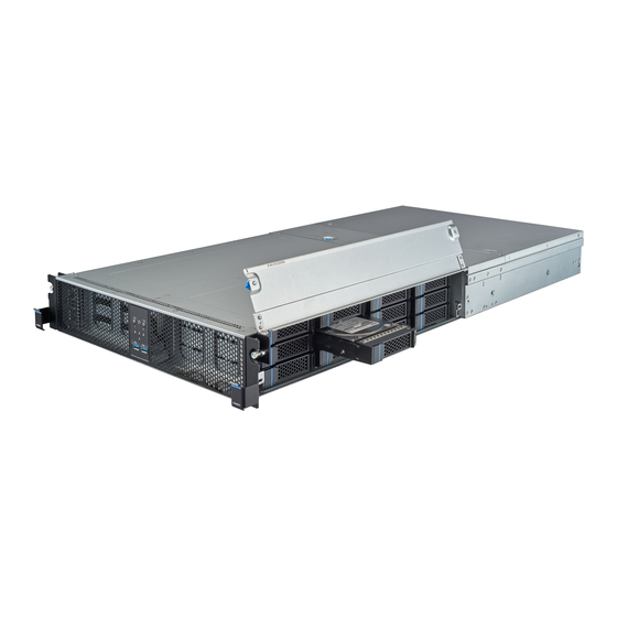
1. Product Overview This RM253 Series offers a high-density enterprise solution for data centers with greater storage and user-friendly maintenance. This 2U chassis supports up to 24-bay 3.5” storage form factors. Tool-less designs such as color-coded touch points and the falcon wing make the top cover removal no longer necessary, providing easy access and maintenance in data centers. -
Page 9: System Features Overview
RM253 Series 1-1 System Features Overview Figure 1 RM253 Overview Figure 2 RM253 Major Component Overview Front Top Cover D. Fan Assembly G. Power Supply Unit Middle Top Cover E. Server board H. 3.5” Hot-swap Cage (Left) Rear Top Cover F. -
Page 10: Front Panel
RM253 Series 1-2 Front Panel Figure 3 RM253 Front Panel A. Front Control Panel Info Tag Rack Handles 1-3 Rear Panel Figure 4 Back Panel with PSU Figure 5 Back Panel Without PSU A. CRPS Power Supply Low Profile Expansion Slots I/O Gasket D. -
Page 11: Front Control Panel
RM253 Series 1-4 Front Control Panel Figure 6 Front Control Panel Table 2 Front Control Panel Label ICON Indicator, Button, or Connector Power Button UID Button Reset Button USB 3.0 HDD Activity LED System Alarm LED LAN1, LAN2 Activity LED... -
Page 12: Storage Configurations
RM253 Series 1-5 Storage Configurations Figure 7 12 x 3.5" Drive-bay Configuration (Right) Figure 8 12 x 3.5" Drive-bay Configuration (Left) Product Overview|12... -
Page 13: Chassis Dimensions
RM253 Series 1-6 Chassis Dimensions Figure 9 Chassis Dimensions Product Overview|13... -
Page 14: Available Rack Mounting Kit Options (Refer To "Installation")
Advisory Note – Available rack and cabinet mounting kits are not designed to support shipment of the server system while installed in a rack. If you choose to do so, Chenbro advises you to verify your shipping configuration with appropriate shock and vibration testing before shipment. Chenbro does not perform shipping tests which cover the complex combination of unique rack offerings and custom packaging options. -
Page 15: System Level Environmental Specifications
RM253 Series 1-8 System Level Environmental Specifications The following table defines the system level specifications under operating and non-operating environments. Table 4 System Environmental Specifications Summary Parameter Specifications Temperature Operating 5º C to 35º C (41º F to 95º F) -
Page 16: System Packaging
1-9 System Packaging The original Chenbro packaging, where the server system is delivered, is designed to provide protection for L5 configuration and tested to meet ISTA (International Safe Transit Association) Test Procedure 1A (2008). The packaging is also designed to be reused for shipment after the system integration has been completed. -
Page 17: System Components Removal And Installation
2. System Components Removal and Installation RM253 series supports the following storage options: Up to 24 x 3.5” hot-swap HDD • 2 x 2.5’’ hot-swap SAS/SATA HDD/SDD (optional) •... -
Page 18: Top Cover Removal And Installation
RM253 Series 2-1. Top Cover Removal and Installation Figure 10 Front Top Cover Removal 1. Loosen two thumb screws on each side of the cover. 2. Loosen all 18 screws on the surface of the top cover. 3. Lift up the cover as shown and remove it vertically. - Page 19 RM253 Series Figure 12 Rear Top Cover Removal 1. Loosen two screws on each side of the rear top cover. 2. Slide the cover backward and remove it vertically. Figure 13 Front Top Cover Installation 1. Align the guide pins of the rear top cover with the grooves on the chassis base.
- Page 20 RM253 Series Figure 14 Rear Top Cover Installation 1. Align the guide pins of the rear top cover with the grooves on the chassis base. 2. Install the cover vertically as shown and slide it forward. 3. Secure with two screws as shown.
-
Page 21: Hot-Swap Hdd Assembly Removal And Installation
RM253 Series Hot-swap HDD Assembly Removal and Installation Figure 16 3.5" Hot-swap HDD Assembly Removal 1. Press the tray button and release the handle as shown. 2. Pull the HDD assembly out of the drive bay. Figure 17 3.5" Hot-swap HDD Assembly Installation 1. - Page 22 RM253 Series Figure 18 3.5" HDD Installation (Tool-less) 1. Slide in the HDD until it aligns with the anchor point of HDD tray as shown. 2. Push down the HDD when it is locked with a click. Figure 19 HDD Removal (Tool-less) 1.
-
Page 23: Fan Assembly Removal And Installation
RM253 Series 2-3 Fan Assembly Removal and Installation Figure 20 Fan Assembly Removal NOTE: Fan Assembly must be removed before Fan Board Maintenance. λ 1. Lift up the latches on both sides of the fan assembly. 2. Remove the fan assembly from the chassis base. - Page 24 RM253 Series Figure 22 Fan Module Removal 1. Press the latches and remove the fan vertically from the fan cage. Figure 23 Fan Module Installation 1. Insert the fan module into the fan cage until it is secured with a click.
- Page 25 RM253 Series 2-4 2-Bay Drive Cage Installation (Back Panel) Figure 24 2.5” 2-Bay Drive Backplane Installation (Back Panel) 1. Attach the backplane to the rear of 2.5” HDD cage. 2. Lock the backplane with the cage by sliding it as shown.
-
Page 26: Full Height Pci-E Card Installation
RM253 Series 2-5 Full Height PCI-e Card Installation Figure 26 Full Height Back Panel Bracket Installation 1. Unfasten two screws on the bracket. 2. Replace the low profile back panel bracket with the full height one. 3. Secure the bracket with two screws. -
Page 27: Psu Installation And Removal
RM253 Series 2-6 PSU Installation and Removal Figure 27 CRPS Module Installation 1. Insert the CRPS module in the PSU cage and push inward until it is secured with a click. Figure 28 CRPS Module Removal 1. Press the latch. -
Page 28: Slide Rail Installation
RM253 Series 2-7 Slide Rail Installation Figure 29 Slide Rail Installation 1 (384-RAL000005SA0) 1. Attach the inner rail to the chassis base while aligning T pins on the side of the system with the slots on the inner rail. 2. Secure the inner rail with two screws on each side. -
Page 29: System Maintenance
RM253 Series 2-8 System Maintenance Figure 31 Removal of Whole System from the Rack 1. Firmly grab the rack handles on both sides. 2. Pull the system out of the rack with two hands. Figure 32 Installation of Whole System into the Rack 1. -
Page 30: Hdd Cage Removal And Installation (For Storage Backplane Maintenance)
RM253 Series 2-9 HDD Cage Removal and Installation (For Storage Backplane Maintenance) Figure 33 HDD Cage Removal (Right) 1. Slide the HDD cage outward until it unlocks. 2. Remove the HDD cage vertically. Figure 34 HDD Cage Removal (Left) 1. Slide the HDD cage outward until it unlocks. - Page 31 RM253 Series Figure 35 HDD Cage Installation (Left) 1. Align the guide pins of the HDD cage with the grooves on the chassis base as shown. 2. Slide the HDD cage inward until it locks. Figure 36 HDD Cage Installation (Right) 1.
-
Page 32: Backplane
3. Backplane Each drive tray includes two LED indicators for drive activity and drive status. Light pipes are integrated into the drive tray direct light emitted from LEDs mounted next to each drive connector on the backplane to the drive tray faceplate, making them visible from the front of the system. -
Page 33: Storage Backplane Options
RM253 Series 3-1 Storage Backplane Options RM253 series supports below backplanes: 12 x 3.5” Mini-SAS HD active backplane • 2 x 2.5’’ SATA/SAS passive backplane (optional) • All available SAS/SATA backplanes include the following common features: 12Gb/s SAS and 6Gb/s SAS& SATA •... -
Page 34: 12-Port 12Gb/S Sas Active Backplane
RM253 Series 3-2 3.5” 12-port 12Gb/s SAS Active Backplane Table 6 Backplane Specifications Specifications Chenbro P/N 380-25311-3000A0 Host Interface Mini-SAS HD Device Interface SFF-8680 Hot-Swap Yes, allows users to replace storage devices on line Display LED indicates storage device status Power LED –... -
Page 35: Table 7 Connector And Pin Header Function Description
RM253 Series Figure 39 Backplane Rear View Table 7 Connector and Pin Header Function Description Label Description Description Drawing Power The backplane includes two power connectors supplying 12V input to the backplane. Power is routed to the backplane via a power cable harness from the power supply. -
Page 36: Table 8 Dip Switch Settings
DISABLE Buzzer DISABLE I2C mode (1) SLAVE MASTER I2C Address (1) Refer to I2C mode. Table 9 I2C Mode for RM253 Series Model Scenario DIP 6 Note RM25324 Standalone BP 1 JC1 interface connect with I2C host. Standalone BP 2 JC1 interface connect with I2C host. -
Page 37: X 2.5" Drive Bay Accessory Kit
RM253 Series 3-3 2 x 2.5” Drive Bay Accessory Kit The 2U product family provides the option to support 2 x SAS/SATA 2.5” HDD/SSDs installed to a drive module mounted in the back of the system. Figure 40 2.5" 2-bay Drive Module The backplane includes several connectors and a jumper block, as defined in the following illustrations. - Page 38 RM253 Series Figure 41 Backplane Front View A. HDD0 B. HDD1 Figure 42 Backplane Rear View Backplane|38...
-
Page 39: Table 12 Connector And Pin Header Function Description
RM253 Series Table 12 Connector and Pin Header Function Description Label Connector Description Drawing Power The backplane includes one power connector supplying 5V/12V input to the backplane. Power is routed to the backplane via a power cable harness from the power supply. -
Page 40: Fanboard
This fanboard provides I2C interface which enables the server board to read the temperature of the HDD Backplane and perform PWM control. Figure 43 Fanboard Table 13 Backplane Specifications Specifications Chenbro P/N 380-25311-3000A0 Cooling FAN connector 1x4 pin * 8 FAN connector 2x3 pin * 6... -
Page 41: Table 14 Connector And Pin Header Function Description
RM253 Series Table 14 Connector and Pin Header Function Description Label Name Description Drawing Power The backplane includes one power connector supplying 12V input to the backplane. Power is routed to the backplane via a power cable harness from the power supply. -
Page 42: Table 15 Connector And Pin Header Function Description
RM253 Series Table 15 Connector and Pin Header Function Description Connector Pin Number Pin Definition Input/output Description Drawing MB TACH Output FAN Clock Output to MB MB PWM Connector MP PWM Input FAN PWM Input from MB Fanboard|42... -
Page 43: Auto Fan Control Algorithm
RM253 Series 4-2 Auto Fan Control Algorithm Parameter Value PWM2 PWM1 TMP1 35 degC TMP2 49 degC hyst 1 degC Note*: Ambient_T > TMP1 Table of Fan Speed and PWM Signal Duty Cycle 1100% Fan speed 9315 23000 ±10% ±10% (ref.) -
Page 44: Cable Routing
5. Cable Routing This chapter provides a guideline for connecting the major cables within the RM253 series Chassis, including: FIO Cable • USB3.0 Cable Routing • Mini SAS HD Cable Routing • I2C Cable Routing •... -
Page 45: Fio Cable Routing
RM253 Series 5-1 FIO Cable Routing Figure 44 FIO Cable Routing RM253 series supports below 2 FIO cables: Display cable for server board such as Intel, Gigabyte, Asrock, etc,. • Display cable for Supermicro server board. (optional) • Pin-Define for FIO cables: Display cable for server board such as Intel, Gigabyte, Asrock, etc,. -
Page 46: Usb 3.0 Cable Routing
RM253 Series Display cable for Supermicro server board. (optional, P/N: 126-30000-0017A0) • 5-2 USB 3.0 Cable Routing Figure 45 USB 3.0 Cable Routing Cable Routing|46... -
Page 47: Mini Sas Hd Cable Routing
RM253 Series 5-3 Mini SAS HD Cable Routing Figure 46 Mini SAS HD Cable Routing 5-4 I2C Cable Routing Figure 47 I2C Cable Routing Cable Routing|47... -
Page 48: Maintenance And Service
CHENBRO also reserves the right to examine the DOA products. If the damage of DOA products is caused by improper action as described above, the customer will be liable for paying the related charge having occurred or paying the fee of the replacements if the DOA products are totally scrapped.
Need help?
Do you have a question about the RM253 Series and is the answer not in the manual?
Questions and answers