Sign In
Upload
Manuals
Brands
Ametek Manuals
Laboratory Equipment
VersaSTAT MC
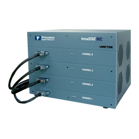
Ametek VersaSTAT MC Manuals
Manuals and User Guides for Ametek VersaSTAT MC. We have
2
Ametek VersaSTAT MC manuals available for free PDF download: Hardware Manual
Ametek VersaSTAT MC Hardware Manual (33 pages)
potentiostat
Brand:
Ametek
| Category:
Laboratory Equipment
| Size: 0.79 MB
Table of Contents
Table of Contents
2
Safety Instructions and Symbols
4
Cleaning Instructions
4
1 Introduction
5
General
5
Hardware Circuitry
5
Potentiostatic Mode
6
Galvanostatic Mode
7
Software
7
Polarity Convention
7
Inspecting Your New Instrument
8
Maintenance, Service, and Support
8
About this Manual
8
2 Safety and Component Placement
10
Safety Considerations
10
Line Voltage Settings and Fuses
10
Defects and Abnormal Stresses
11
Component Placement
11
Ventilation
12
Radio Frequency Interference
12
Transient Sensitivity
13
3 Installation
15
Enabling the USB Port on Your PC
15
Connectors and Indicators
15
Rear Panel
15
Front Panel
17
Connecting to the PC and Cell
18
Connecting to the PC
18
Connecting the Cell
18
4 Specifications and Pinouts
22
Electronic Specifications
22
System Performance
22
Power Amplifier
22
Voltage Control
22
Current Control
22
Differential Electrometer
22
Voltage Measurement
23
Current Measurement
23
Ir Compensation
23
Potential/Current Control
23
Impedance Specifications (if Impedance Option Available)
23
Physical and Power Specifications
24
Standard Environmental Conditions
24
AUXILIARY INTERFACE Pinouts
25
Cell Cable Pinouts
25
5 Available Options
26
High Current Option
26
Advanced Auxiliary Interface Option
26
Power Booster
26
Appendix 1
27
Versastat MC External Power Booster Connections
29
Advertisement
Ametek VersaSTAT MC Hardware Manual (21 pages)
Low Current Interface
Brand:
Ametek
| Category:
Measuring Instruments
| Size: 0.61 MB
Table of Contents
Table of Contents
2
Safety Instructions and Symbols
4
Cleaning Instructions
4
1 Introduction
5
About this Manual
5
About the Low Current Interface (LCI)
5
Figure 1. Versastat LC Assembly
5
Figure 2. LCI-Potentiostat Interface Cable
6
LCI Interface Cable
6
LCI Main Body
6
Table 1. Low Current Interface
6
Figure 3. LCI Cell Cable Panel (Left) and Potentiostat Interface Panel (Right)
7
Figure 4. LCI with Cell Cables Connected Across Internal Feedback (Dummy Cell)
7
LCI Cell Cables
7
Inspecting Your New Instrument
8
Maintenance, Service, and Support
8
Figure 5. Cell Cables
8
2 Installation
9
Connect Interface Cable to LCI Main Body
9
Connect Interface Cable to Potentiostat Cell Interface
9
LCI Calibration
9
Connect Cell Cables to LCI Front Panel
9
Calibration
9
Figure 6. Calibration Required Message
10
Figure 7. Calibration Procedure
10
Figure 8. Calibrate Message
11
Figure 9. CE Not Connected
11
Figure 10. Calibration Question Message Box
11
Figure 11. Connect Leads Calibrate Message
12
Figure 12. LCI Inside Faraday Box
12
LCI Checkout Procedure
13
Figure 13. Calibration Complete Message
13
Figure 14. Versastudio Experiment Operational Screen
14
3 Measurement of Small Current Signals
15
Faraday Shield
15
Figure 15. K0269B Faraday Box
15
Avoiding External Noise Sources
16
Cell Design
16
Lead and Electrode Placement
16
Cell Construction
16
Reference Electrode
16
Experimental Properties
16
Auto Current Ranging
16
LCI Bandwidth Limits
17
Table 2. Time Constants
17
4 Specifications
19
Electronic Specifications
19
System Performance
19
Power Amplifier
19
Differential Electrometer
19
Current Measurement
19
Current Control
19
Physical Specifications
19
Standard Environmental Conditions
20
5 Warranty
21
Advertisement
Related Products
Ametek VersaSTAT LC Series
Ametek VersaSTAT 4
Ametek VersaSCAN
Ametek VDS 200Q Series
Ametek VDS 200Q25.2
Ametek VDS 200Q100.2
Ametek VDS 200Q200.2
Ametek VSS 500N
Ametek Magnetrol V35
Ametek VDS 200Q150.2
Ametek Categories
Measuring Instruments
Test Equipment
Power Supply
Controller
Laboratory Equipment
More Ametek Manuals
Login
Sign In
OR
Sign in with Facebook
Sign in with Google
Upload manual
Upload from disk
Upload from URL