Table of Contents
Advertisement
Available languages
Available languages
Advertisement
Chapters
Table of Contents

Related Manuals for HomeMatic HM-LC-Sw1-PB-FM


Summary of Contents for HomeMatic HM-LC-Sw1-PB-FM
- Page 1 Installations- und Bedienungsanleitung (S. 2) Installation and operating manual (S. 26) Schalt-/Jalousieaktoren Unterputzmontage, mit Tasteraufsatz: Switch /blind actuators flush mount, with pushbutton: HM-LC-Sw1-PB-FM HM-LC-Sw2-PB-FM HM-LC-Bl1-PB-FM...
- Page 2 1. Ausgabe Deutsch 06/2009 Dokumentation © 2009 eQ-3 Ltd., Hong Kong Alle Rechte vorbehalten. Ohne schriftliche Zustim- mung des Herausgebers darf dieses Handbuch auch nicht auszugsweise in irgendeiner Form reproduziert werden oder unter Verwendung elektronischer, me- chanischer oder chemischer Verfahren vervielfältigt oder verarbeitet werden.
-
Page 3: Table Of Contents
Funktion......7 Allgemeine Systeminformation zu HomeMatic 11 Allgemeine Hinweise zum Funkbetrieb ..12 Installation . -
Page 4: Hinweise Zu Dieser Anleitung
Hinweise zu dieser Anleitung Lesen Sie diese Anleitung sorgfältig, bevor Sie ihre HomeMatic Komponenten in Betrieb nehmen. Bewahren Sie die Anleitung zum späteren Nach- schlagen auf! Wenn Sie das Gerät anderen Personen zur Nutzung überlassen, übergeben Sie auch diese Bedienungs- anleitung. - Page 5 Der Betrieb des Gerätes ist ausschließlich am 230V/50Hz-Wechselspannungsnetz zulässig. Arbeiten am 230V-Netz dürfen nur von einer Elektro- Fachkraft (nach VDE 0100) erfolgen. Dabei sind die geltenden Unfallverhütungsvorschriften zu beach- ten. Zur Vermeidung eines elektrischen Schlages vor Arbeiten am Gerät Netzspannung freischalten (Si- cherungsautomat abschalten).
- Page 6 Schaltaktor: Beachten Sie vor Anschluss eines Verbrauchers unbedingt die technischen Daten, insbesondere die maximal zulässige Schaltleistung des Relais und Art des anzuschließenden Verbrauchers! Alle Lastanga- ben beziehen sich auf ohmsche Lasten! Jalousieaktor: Der Aktor ist nur für 230V Wechselstrommotoren geeignet! Schließen Sie keine Drehstrommotoren und keine Gleichstrommotoren an! Sollen am Ausgang des Aktors Motoren parallel ge-...
-
Page 7: Funktion
Funktion Die Aktoren steuern angeschlossene Verbraucher aufgrund von empfangenen Funkbefehlen. Befehle werden ausgesandt durch Betätigung von Tastern, Fernbedienungen oder über eine Softwareoberflä- che. Weiterhin ist es möglich, Aktoren über ange- lernte Sensoren anzusteuern. Die Sensoren senden (wie ein Taster) beim Eintreten eines Ereignisses einen Befehl. - Page 8 Die Aktoren bestehen aus drei Teilen (A, B, C): HM-LC-Sw1-PB-FM HM-LC-Sw2-PB-FM HM-LC-Bl1-PB-FM 1-fach-Rahmen Aktor für UP-Montage Tastwippe(n)
- Page 9 HM-LC-Sw1-PB-FM Anschluss für Tasterwippe Anlern-/Test-Taste mit Geräte-LED Anschlussklemmen HM-LC-Sw2-PB-FM Anschluss für Tasterwippe Anlern-/Test-Taste Kanal 1 mit Geräte-LED Anlern-/Test-Taste Kanal 2 Anschlussklemmen...
- Page 10 HM-LC-Bl1-PB-FM Anschluss für Tasterwippe Anlerntaste mit Geräte-LED und Test-Taste „herauf” Test-Taste „herunter” Anschlussklemmen...
-
Page 11: Allgemeine Systeminformation Zu Homematic
Allgemeine Systeminformation zu HomeMatic Dieses Gerät ist Teil des HomeMatic Haussteuersy- stems und arbeitet mit dem bidirektionalen BidCoS ® Funkprotokoll. Alle Geräte werden mit einer Standardkonfiguration ausgeliefert. Darüber hinaus ist die Funktion des Gerätes über ein Programmiergerät und Software konfigurierbar. Welcher weitergehende Funktions-... -
Page 12: Allgemeine Hinweise Zum Funkbetrieb
Gegebenheiten vor Ort eine wichtige Rolle. Hiermit erklärt die eQ-3 Entwicklung GmbH, dass sich dieses Gerät in Übereinstimmung mit den grundlegenden Anforderungen und den anderen relevanten Vorschriften der Richtlinie 1999/5/EG befindet. Die vollständige Konformitätserklärung finden Sie unter www.HomeMatic.com. -
Page 13: Installation
Installation Die Aktoren zur Unterputzmontage eignen sich zur Montage in Installationsdosen. Bei Einbau von mehreren Unterputzaktoren in nebeneinander oder übereinander liegenden Installationsdosen (verbunden oder unver- bunden) darf ein Gesamtschaltstrom von 16 A nicht überschritten werden! Der Anschluss der beschriebenen Aktoren ist in den nachfolgenden Anschlussbildern dargestellt. - Page 14 Geräte-LED auf. - Stecken Sie für einen Funktionstest die Tastwippe auf und testen Sie deren Funktion. - Nehmen Sie dann die Tastwippe wieder ab, damit Sie zum Anlernen die Anlerntaste erreichen können. HM-LC-Sw1-PB-FM Anschluss Außenleiter Geschaltete Phase Anschluss Neutralleiter...
- Page 15 HM-LC-Sw2-PB-FM Anschluss Außenleiter Geschaltete Phase Kanal 1 Geschaltete Phase Kanal 2 Anschluss Neutralleiter...
- Page 16 HM-LC-Bl1-PB-FM Anschluss Außenleiter Geschaltete Phase „AB“ Geschaltete Phase „AUF“ Anschluss Neutralleiter...
-
Page 17: Inbetriebnahme
Zugelassene Leitungsquerschnitte zum Anschluss an die UP-Aktoren: - starre Leitung, 0,20 – 1,50 mm Inbetriebnahme 7.1 Einfache Bedienfunktionen mit Anlern-/ Test-Taste und Tastwippe Sie können den Aktor über die Anlern- und die Test- taste oder die Tastwippe sofort bedienen (Anlernen nicht erforderlich) und die korrekte elektrische In- stallation überprüfen. -
Page 18: Anlernen
7.2 Anlernen Bitte lesen Sie diesen Abschnitt erst vollständig, be- vor sie mit dem Anlernen beginnen! Zum Anlernen müssen beide zu verknüpfenden Ge- räte in den Anlernmodus gebracht werden und der gewünschte Kanal zum Anlernen muss ausgewählt werden. Die Aktoren besitzen eine bzw. zwei Anlerntasten. - Zum Anlernen an einen bestimmten Kanal des Ak- tors halten Sie die zugehörige Anlerntaste für etwa 4s gedrückt. -
Page 19: Bedienung
Bedienung Nach dem Anlernen stehen einfache Bedienfunktio- nen über die angelernten Bedienelemente zur Ver- fügung. Daneben ist die Direkt-Bedienung am Gerät über die Tasterwippen möglich. 8.1 Schaltaktoren Je nach angelerntem Bedienelement lässt sich der Schaltaktor im Zweitasten-AN/AUS Betrieb oder im Toggle-Betrieb ansteuern. -
Page 20: Zurücksetzen In Den Auslieferungszustand
Zurücksetzen in den Ausliefe- rungszustand Um den Aktor in den Auslieferungszustand zurück- zusetzen versetzen Sie das Gerät über die (erste) Kanaltaste in den Anlernmodus (mindestens 4 Se- kunden Taste gedrückt halten). Befindet sich das Gerät im Anlernmodus, halten Sie erneut die (erste) Kanaltaste für mindestens 4 Sekunden gedrückt. -
Page 21: Anzeige Des Betriebszustandes
Bemerkung: Beim Funk-Schaltaktor 2fach ist nur eine LED für beide Kanäle vorhanden. Daher wird ein entsprechender Blinkcode angezeigt sobald ein Kanal im entsprechenden Zustand ist. 10.2 Anzeige des Betriebszustandes Sobald ein Relais des Gerätes angezogen ist leuch- tet die Geräte-LED dauerhaft. Nach Konfiguration des Aktors über die Zentrale oder über ein Programmiertool zeigt die Geräte-LED neben den beschriebenen noch zusätzliche Zustän-... - Page 22 und das Gerät nimmt seine eigentliche Funktion nicht auf. Sollte der Test ohne Fehler durchlaufen, sendet der Aktor ein Funktelegramm mit seiner Statusinformati- on aus. Damit bei Spannungswiederkehr (etwa nach Netzspannungsausfall oder Abschaltung) nicht alle Aktoren gleichzeitig senden, wartet der Aktor eine zufällige Verzögerungszeit vor dem Senden.
-
Page 23: Wartung Und Reinigung
12 Wartung und Reinigung Das Produkt ist wartungsfrei. Überlassen Sie eine Reparatur einer Fachkraft. Die Geräte HM-LC-Sw1-PB-FM, HM-LC- Sw2-PB-FM und HM-LC-Bl1-PB-FM enthal- ten eine interne Gerätesicherung! Diese Sicherung dient dem Schutz der Geräterelais vor zu großer Strombelastung. Sollte das Gerät überlastet werden und die Sicherung auslösen, kann sie von einem... -
Page 24: Technische Daten
0,5 W Schutzart: IP20 Schutzklasse: Gehäuse: Gehäusefarbe: Grün Abmessungen: 70 x 70 x 34 mm (H x B x T) HM-LC-Sw1-PB-FM Relais: Schliesser Schaltvermögen: 5 A (ohmsche Last) HM-LC-Sw2-PB-FM Relais: 2 x Schliesser Schaltvermögen: 5 A (Summe beider Ka- näle, ohmsche Last) - Page 25 Entsorgungshinweis Gerät nicht im Hausmüll entsorgen! Elektro- nische Geräte sind entsprechend der Richtlinie über Elektro- und Elektronik-Altgeräte über die örtlichen Sammelstellen für Elektronik-Altgeräte zu entsorgen. Das CE-Zeichen ist ein Freiverkehrszeichen, das sich ausschließlich an die Behörden wendet und keine Zusicherung von Eigenschaften beinhaltet.
- Page 26 Issue 1 English 06/2009 Documentation © 2009 eQ-3 Ltd, Hong Kong All rights reserved. No parts of this manual may be reproduced or processed in any form using electronic, mechanical or chemical processes in part or in full without the prior explicit written permission of the publisher.It is quite possible that this manual has printing errors or defects.
- Page 27 Function......31 General system information about HomeMatic ..... . . 35 General information about radio operation . 36 Installation .
-
Page 28: Information About This Manual
Information about this manual Read this manual carefully before starting to use your HomeMatic components. Keep the manual handy so you can refer to it at a later date! If you hand over the device to other persons for use, please hand over the operating manual as well. - Page 29 electricians (to VDE 0100) are permitted to carry out work on the 230 V mains. Applicable accident prevention regulations must be complied with whilst such work is being carried out. To avoid electric shock, disconnect the mains voltage prior to starting work on the device (trip the miniature circuit-breaker).
- Page 30 Switch actuator: It is absolutely essential to take the technical data (in particular the maximum permissible switching capacity of the relay and the type of load to be connected) into account before connecting a load. All load data relates to ohmic loads. Blind and shutter actuator: The actuator is only suitable for 230 V AC motors.
-
Page 31: Function
Function Actuators control connected loads in accordance with the wireless commands they receive. Commands are transmitted by actuating buttons or remote controls or via a software interface. It is also possible to control actuators via taught-in sensors. When an event occurs, the sensors transmit a command (in the same way as a button). - Page 32 The actuators consist of three parts (A, B, C): HM-LC-Sw1-PB-FM HM-LC-Sw2-PB-FM HM-LC-Bl1-PB-FM 1-way frame Actuator for flush mounting Pushbutton rocker(s)
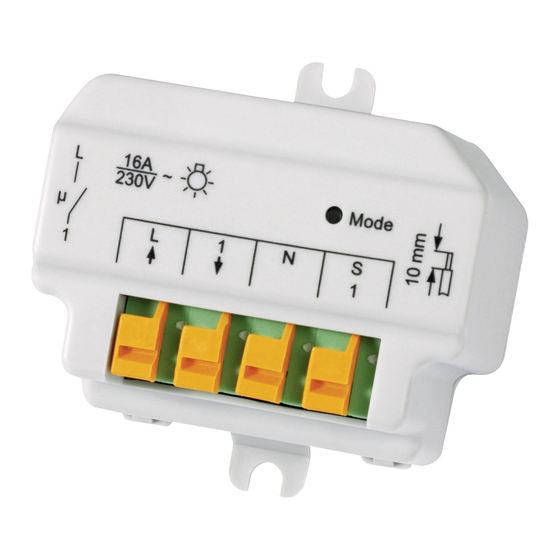
- Page 33 HM-LC-Sw1-PB-FM Connection for pushbutton rocker Teach-in/test button with device LED Connecting terminals HM-LC-Sw2-PB-FM Connection for pushbutton rocker Teach-in/test button channel 1 with device LED Teach-in/test button channel 2 Connecting terminals...
- Page 34 HM-LC-Bl1-PB-FM Connection for pushbutton rocker Teach-in button with device LED and test button “up” Test button “down” Connecting terminals...
-
Page 35: General System Information About Homematic
General system information about HomeMatic This device is part of the HomeMatic home control system and works with the bi-directional BidCoS ® wireless protocol. All devices are delivered in a standard configuration. The functionality of the device can also be configured with a programming device and software. -
Page 36: General Information About Radio Operation
Entwicklung GmbH hereby declares that this device conforms with the essential requirements and other relevant regulations of Directive 1999/5/EC. The full declaration of conformity is provided at www.HomeMatic.com. -
Page 37: Installation
Installation The actuators for flush mounting are suitable for mounting in installation boxes. If a number of flush-mounted actuators are to be mounted in installation boxes located next to or above one another (connected or not connected), the total switched current must not exceed 16 A. - Page 38 - Connect the pushbutton rocker to run a function test and check its function. - Then remove the pushbutton rocker so that you can access the teach-in button for teach-in purposes. HM-LC-Sw1-PB-FM Phase conductor connection Switched phase Neutral conductor connection...
- Page 39 HM-LC-Sw2-PB-FM Phase conductor connection Switched phase channel 1 Switched phase channel 2 Neutral conductor connection...
- Page 40 HM-LC-Bl1-PB-FM Phase conductor connection Switched phase “DOWN” Switched phase “UP” Neutral conductor connection...
-
Page 41: Start-Up
Permitted cable cross sections for connecting to flush-mounted actuators: - Rigid cable, 0.20 – 1.50 mm Start-up 7.1 Simple operator functions using the teach-in/test button and pushbutton rocker You can put the actuator into operation immediately using the teach-in and test button or the pushbutton rocker (no teaching-in required) and check that the electrical installation has been performed correctly. -
Page 42: Teaching-In
7.2 Teaching-in Please read this entire section before starting the teach-in procedure. To execute the teach-in procedure, both of the devices to be connected must be in teach-in mode and the channel to be taught-in must be selected. The actuators have one or two teach-in buttons. - To teach-in to a specific actuator channel, press and hold down the corresponding teach-in button for approximately four seconds. -
Page 43: Operation
Operation After teach-in has been performed, simple operator functions are available via the taught-in control elements. Operation directly on the device is also possible using the pushbutton rockers. 8.1 Switch actuators Depending on the taught-in control element, the switch actuator can be controlled by means of an ON/OFF pair of buttons or by toggling. -
Page 44: Resetting To The Initial State
Resetting to the initial state To reset the actuator to the initial state, put the device into teach-in mode using the (first) channel button (hold it down for at least four seconds). If the device is in teach-in mode, hold the (first) channel button down for at least four seconds again. -
Page 45: Operating Status Display
Note: The 2-way wireless switch actuator has just one LED for both channels. Therefore, a corresponding flashing code will appear as soon as a channel is in the appropriate state. 10.2 Operating status display The device LED will light up continuously as soon as a device relay picks up. - Page 46 If the test is completed without errors, the actuator transmits a wireless telegram containing its status information. To prevent all actuators from transmitting at the same time when power is recovered (after a mains power failure or a disconnection, for example), there is a random delay before the actuator transmits.
-
Page 47: Maintenance And Cleaning
The product does not require any maintenance. Enlist the help of an expert to carry out any repairs. The HM-LC-Sw1-PB-FM, HM-LCSw2-PB-FM and HM-LC-Bl1-PB-FM devices have internal fuse protection. The fuses protect the device relays against excessive current load. If the device is overloaded and the fuse blows, it can be replaced by an expert. -
Page 48: Technical Data
Degree of protection: IP20 Protection class: Housing: Housing colour: Green Dimensions: 70 x 70 x 34 mm (H x W x D) HM-LC-Sw1-PB-FM Relay: NO contact Switching capacity: 5 A (ohmic load) HM-LC-Sw2-PB-FM Relay: 2 x NO contacts Switching capacity:... - Page 49 Instructions for disposal Do not dispose of the device with regular domestic waste. Electronic devices must be disposed of in accordance with the Waste Electrical and Electronic Equipment Directive via local disposal points for electronic waste. The CE sign is a free trade sign addressed exclusively to the authorities and does not include any warranty of any properties.
- Page 52 eQ-3 AG Maiburger Straße 29 D-26789 Leer www.eQ-3.com...
Need help?
Do you have a question about the HM-LC-Sw1-PB-FM and is the answer not in the manual?
Questions and answers