Chapters
Table of Contents

Related Manuals for HomeMatic HM-LC-Sw4-DR-2


Summary of Contents for HomeMatic HM-LC-Sw4-DR-2
- Page 1 Installations- und Bedienungsanleitung (S. 2) Installation and operating manual (p. 30) Funk-Schaltaktor 4-fach, Hutschienenmontage Wireless Switch Actuator 4-channel, DIN rail mount HM-LC-Sw4-DR-2...
- Page 2 Dokumentation © 2016 eQ-3 AG, Deutschland Alle Rechte vorbehalten. Ohne schriftliche Zustimmung des Herausgebers darf dieses Handbuch auch nicht auszugsweise in irgendeiner Form reproduziert werden oder unter Verwendung elektronischer, mechanischer oder chemischer Verfahren vervielfältigt oder verarbeitet werden. Es ist möglich, dass das vorliegende Handbuch noch drucktechnische Mängel oder Druckfehler aufweist.
-
Page 3: Table Of Contents
Anlernen ......19 7.2.1 Anlernen an Homematic Geräte... 19 7.2.2 Anlernen an eine Homematic Zentrale. -
Page 4: Hinweise Zu Dieser Anleitung
Nutzung überlassen, übergeben Sie auch diese Bedie- nungsanleitung. Benutze Symbole: Achtung! Hier wird auf eine Gefahr hingewiesen. Hinweis. Dieser Abschnitt enthält zusätzliche wichtige Informationen. Hinweis. Dieser Abschnitt enthält zusätzliche wichtige Informationen zur Verwendung des Gerätes in Verbindung mit der Homematic Zentrale. -
Page 5: Gefahrenhinweise
Gefahrenhinweise Gefahrenhinweise Bei Sach- oder Personenschäden, die durch unsachgemäße Handhabung oder Nichtbeach- ten der Sicherheitshinweise verursacht werden, übernehmen wir keine Haftung. In solchen Fäl- len erlischt jeder Gewährleistungsanspruch! Für Folgeschäden übernehmen wir keine Haf- tung! Beachten Sie insbesondere die Sicher- heitshinweise und Handlungsanweisungen im Kapitel „Installation“! Der beschriebene Aktor ist Teil einer Ge-... - Page 6 Gefahrenhinweise spannung frei (Sicherungsautomat abschalten). Bei Nichtbeachtung der Installationshinweise können Brand oder andere Gefahren entste- hen. Betreiben Sie das Gerät nur in trockener, staubfreier Umgebung, setzen Sie es keinem Einfluss von Feuchtigkeit, Staub, Vibrationen, ständiger Sonnen- oder anderer Wärmeein- strahlung, übermäßiger Kälte und keinen me- chanischen Belastungen aus.
- Page 7 Gefahrenhinweise Das Gerät ist nicht zum Freischalten geeignet. Das Öffnen des Gerätes birgt die Gefahr eines Stromschlages. Im Fehlerfall schicken Sie das Gerät an den Service. Beachten Sie beim Anschluss an die Geräte- klemmen die hierfür zulässigen Leitungsarten und Leitungsquerschnitte. Verwenden Sie das Gerät nicht, wenn es von außen erkennbare Schäden z.
- Page 8 Gefahrenhinweise Das Gerät ist kein Spielzeug, erlauben Sie Kin- dern nicht damit zu spielen. Lassen Sie das Verpackungsmaterial nicht achtlos liegen, Plastikfolien/-tüten, Styroporteile, etc., könnten für Kinder zu einem gefährlichen Spielzeug werden. Beachten Sie vor Anschluss eines Verbrau- chers unbedingt die technischen Daten, insbe- sondere die maximal zulässige Schaltleistung der Relais und Art des anzuschließenden Ver- brauchers.
-
Page 9: Funktion
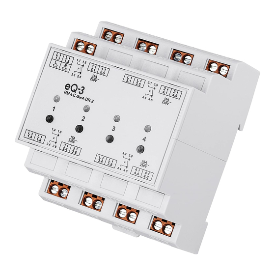
Sie können den Schaltaktor per Funk über Taster, Fernbedienungen oder über die Bedienoberfläche „WebUI“ steuern. Zusätzlich ist es möglich, den Schaltaktor über angelernte Homematic Sensoren an- zusteuern. Die Sensoren senden beim Eintreten eines Ereignisses einen Befehl. Genaueres dazu ist der An- leitung des entsprechenden Sensors zu entnehmen. - Page 10 Funktion Geräteübersicht: Kanaltasten für Kanal 1-4 Kanal-LEDs für Kanal 1-4 Spannungsversorgung 230 V Schaltkanal 1 Schaltkanal 2 Schaltkanal 3 Schaltkanal 4...
-
Page 11: Allgemeine Systeminformation Zu Homematic
Homematic Funkprotokoll. Alle Geräte werden mit einer Standardkonfiguration ausgeliefert. Darüber hinaus können Sie die Funktio- nen des Gerätes über die Homematic Zentrale CCU2 in Verbindung mit der WebUI konfigurieren. Welcher weitergehende Funktionsumfang sich daraus ergibt, und welche Zusatzfunktionen sich im Homematic System im Zusammenspiel mit weiteren Komponenten ergeben, entnehmen Sie bitte dem Homematic WebUI Handbuch. - Page 12 • Aktor-Gruppen können nicht mehr gleichzeitig Befehle ausführen. Weitere Informationen zur gesicherten Übertra- gung (AES) finden Sie im Homematic WebUI Handbuch unter www.homematic.com. Hiermit erklärt die eQ-3 AG, dass sich dieses Gerät in Übereinstimmung mit den grundlegenden Anforde- rungen und den anderen relevanten Vorschriften der Richtlinie 1999/5/EG befindet.
-
Page 13: Installation
Installation Installation 6.1 Installationshinweise Beachten Sie die Installationsvorschriften für Installationen in Verteilersystemen. Der Stromkreis, an den das Gerät und die Last angeschlossen werden, muss mit einem Lei- tungsschutzschalter gemäß EN60898-1 (Auslö- secharakteristik B oder C, max. 16 A Nennstrom, min. 6 kA Abschaltvermögen, Energiebegrenzungsklasse 3) abgesichert sein. - Page 14 Installation Installation nur durch Personen mit ein- schlägigen elektrotechnischen Kenntnissen und Erfahrungen!* Durch eine unsachgemäße Installation gefährden Sie: • Ihr eigenes Leben; • das Leben der Nutzer der elektrischen Anlage. Mit einer unsachgemäßen Installation riskieren Sie schwere Sachschäden, z. B. durch Brand. Es droht für Sie die persönliche Haftung bei Personen- und Sachschäden.
-
Page 15: Montage Und Installation
Installation System) und die daraus folgenden Anschlussbedingungen (klassische Nullung, Schutzerdung, erforderliche Zusatzmaß- nahmen etc.). 6.2 Montage und Installation Um den Schaltaktor auf einer Hutschienen zu installieren, gehen Sie wie folgt vor: • Setzen Sie das Gerät auf die Hutschiene auf und verriegeln Sie es. - Page 16 Installation...
- Page 17 Installation Klemme Funktion Spannungsversorgung (Außenleiter) Spannungsversorgung (Neutralleiter) 1.1, 1.5 Außenleiteranschluss Kanal 1 2.1, 2.5 Geschaltete Phase Kanal 1 3.1, 3.5 Außenleiteranschluss Kanal 2 4.1, 4.5 Geschaltete Phase Kanal 2 1.4, 1.8 Außenleiteranschluss Kanal 3 2.4, 2.8 Geschaltete Phase Kanal 3 3.4, 3.8 Außenleiteranschluss Kanal 4 4.4, 4.8...
-
Page 18: Inbetriebnahme
Kanal. Sie können den Aktor über einen kurzen Tastendruck direkt bedienen und die korrekte elekt- rische Installation überprüfen. Das Anlernen an die Homematic Zentrale ist dafür nicht erforderlich. Der lange Tastendruck (länger als 4 Sekunden) versetzt den entsprechenden Kanal des Aktors in den Anlernmodus (vgl. -
Page 19: Anlernen
7.2 Anlernen Bitte lesen Sie diesen Abschnitt vollständig, be- vor Sie mit dem Anlernen beginnen. Damit der Schaltaktor in Ihr Homematic System integriert werden und mit anderen Homematic Kom- ponenten (z. B. eine Homematic Fernbedienung) kom- munizieren kann, muss das Gerät zunächst angelernt werden. -
Page 20: Anlernen An Eine Homematic Zentrale
• steuern und konfigurieren, • direkt mit anderen Geräten verknüpfen oder • in Zentralenprogrammen nutzen zu können, muss es zunächst an die Homematic Zentrale an- gelernt werden. Das Anlernen neuer Geräte an die Zentrale erfolgt über die Homematic Bedienoberfläche „WebUI“. - Page 21 Jede Komponente kann immer nur an eine Zen- trale angelernt werden. Halten Sie beim Anlernen einen Mindestabstand von 50 cm zwischen den Homematic Geräten und der Zentrale ein. Zum Anlernen Ihres Gerätes an die Zentrale gehen Sie wie folgt vor: •...
- Page 22 Inbetriebnahme • Der Anlernmodus ist für 60 Sekunden aktiv. Das Info- feld zeigt die aktuell noch verbleibende Anlernzeit. • Versetzen Sie innerhalb dieser Anlernzeit den Schaltaktor in den Anlernmodus. Halten Sie eine beliebige Kanaltaste (A) für mindestens 4 Sekunden gedrückt. Dauerhaftes Blinken der Kanal-LED (B) signalisiert den Anlernmodus.
- Page 23 Posteingang wie im Abschnitt „Neu angelernte Geräte konfigurieren“ beschrieben. Neu angelernte Geräte konfigurieren Nachdem Sie Ihren Schaltaktor an die Homematic Zentrale angelernt haben, wird er in den „Posteingang“ verschoben. Hier muss das Gerät und die dazugehö- rigen Kanäle zunächst konfiguriert werden, damit es für Bedien- und Konfigurationsaufgaben zur Verfügung...
-
Page 24: Bedienung
Bedienung Bedienung Nach dem Anlernen stehen einfache Bedienfunktionen über das angelernte Homematic Gerät zur Verfügung. Über das angelernte Gerät (z. B. eine Fernbedienung) können Sie den Schaltaktor mit einer Taste (Toogle- Funktion) oder zwei Tasten ein- und ausschalten. Werkseinstellungen wiederherstellen Die Werkseinstellungen des Gerätes können... -
Page 25: 10 Rückmeldungen Der Geräte-Led
Rückmeldungen der Geräte-LED 10 Rückmeldungen der Geräte-LED 10.1 Blinkcodes Verschiedene Zustände des Aktors werden durch Blinken der Kanal-LEDs (B) angezeigt: Blinken Bedeutung Langsames Blinken Anlernmodus Schnelles Blinken Reset 1 x lang, 1 x kurz Sende-Limit (Duty-Cycle) erreicht 1 x lang, 2 x kurz Gerät defekt 10.2 Anzeige des Betriebszustandes Sobald das Relais eines Kanals angezogen (bzw. -
Page 26: Verhalten Nach Spannungswiederkehr
Spannungswiederkehr Nach dem Einschalten der Betriebsspannung (bzw. Wiederkehr der Netzspannung) überprüft der Aktor seine Komponenten und sendet ein Funktelegramm mit einer Statusinformation an die Homematic Zent- rale. Wird nach dem Einschalten der Betriebsspannung (bzw. Wiederkehr der Netzspannung) ein Fehler fest- gestellt, blinken alle Kanal-LEDs (B). -
Page 27: Wartung Und Reinigung
Wartung und Reinigung 12 Wartung und Reinigung Das Produkt ist wartungsfrei. Überlassen Sie eine Reparatur einer Fachkraft. Trennen Sie das Gerät vor der Reinigung vom Strom- netz. Reinigen Sie das Gerät nur mit einem trockenen Leinentuch, das bei starken Verschmutzungen leicht angefeuchtet sein kann. -
Page 28: Technische Daten
Technische Daten 13 Technische Daten Geräte-Kurzbezeichnung: HM-LC-Sw4-DR-2 Versorgungsspannung: 230 V/50 Hz Stromaufnahme: 20 mA max. Leistungsaufnahme Ruhebetrieb: 0,25 W Ausgänge: 4 potentialfreie Relais- Schaltausgänge Relais: Schließer Lastart: ohmsche Last Maximale Schaltleistung: 3680 W (230 V/50 Hz/16 A) pro Kanal, Summe aller Kanäle max. - Page 29 Technische Daten Duty Cycle: < 1 % pro h Schutzart: IP20 Schutzklasse: Umgebungstemperatur: -10 bis +55 °C Abmessungen (B x H x T): 72 x 65 x 87 mm (4 TE, Standard- Hutschienengehäuse) Gewicht: 189 g Technische Änderungen vorbehalten. Entsorgungshinweis Gerät nicht im Hausmüll entsorgen! Elektro- nische Geräte sind entsprechend der Richtlinie über Elektro- und Elektronik-Altgeräte über die...
- Page 30 Documentation © 2016 eQ-3 AG, Germany All rights reserved. This manual may not be reproduced in any format, either in whole or in part, nor may it be duplicated or edited by electronic, mechanical or chemical means, without the written consent of the publisher.
- Page 31 7.2.1 Teaching-in directly to Homematic devices . . 47 7.2.2 Teaching-in to a Homematic Central Control Unit . 48 Operation ......52 Restore factory settings .
-
Page 32: Information About This Manual
Symbols used: Attention! This indicates a hazard. Please note: This section contains important additional information. Please note: This section contains additional important information about using the device in connection with the Homematic Central Control Unit. -
Page 33: Hazard Information
Hazard information Hazard information We do not assume any liability for damage to property or personal injury caused by improper use or the failure to observe the safety instructions. In such cases, any claim under warranty is extinguished! For consequential damages, we assume no liability! Especially observe the safety and handling instructions in the chapter “Installation”! - Page 34 Hazard information To avoid electric shocks from the device, please disconnect the mains voltage (trip the miniature circuit-breaker) prior to starting work on the device. Non-compliance with the installation instructions can cause fire or introduce other hazards. The device may only be operated in dry and dust-free environment and must be protected from the effects of moisture, dust, vibrations, solar or other methods of heat radiation, cold...
- Page 35 Hazard information The device has not been designed to support safety disconnection. There is a risk of electric shock if the device is opened. In the event of an error, have the device checked by an expert. When connecting to the device terminals, take the permissible cable types and cable cross sections into account.
- Page 36 Hazard information The device is not a toy; do not allow children to play with it. Do not leave packaging material ly- ing around, plastic films/bags, pieces of poly- styrene etc., can be dangerous in the hands of a child. It is absolutely essential to take the technical data (in particular the maximum permissible switching capacity of the relay and the type of...
-
Page 37: Function
“WebUI”. Furthermore, the switch actuator can be con- trolled via connected Homematic sensors. When an event occurs, the sensors transmit a command to the switching actuator. Refer to the manual for the corre- sponding sensor for more detailed information. - Page 38 Function Device overview Channel buttons for channel 1-4 Channel LEDs for channel 1-4 Supply voltage 230 V Switching channel 1 Switching channel 2 Switching channel 3 Switching channel 4...
-
Page 39: General Information About The Homematic System
General information about the Homematic system General information about the Homematic system This device is part of the Homematic smart home system and works with the bidirectional Homematic wireless protocol. All devices are delivered in a standard configuration. In addition, you can configure all the device functionalities via the Homematic Central Control Unit CCU2 in con- nection with the WebUI. - Page 40 • actuator groups are unable to execute commands simultaneously. Please refer to the Homematic WebUI Manual at www.homematic.com for further information on secured operation (AES). eQ-3 AG hereby declares that this device complies with the essential requirements and other relevant reg- ulations of Directive 1999/5/EC.
-
Page 41: Installation
Installation Installation 6.1 Installation instructions Refer to the relevant installation regulations when performing installations in distribution systems. The circuit to the which the device and the load will be connected has to be secured by a cable protection switch in accordance with EN60898- 1 (tripping characteristic B or C, max. - Page 42 Installation Only to be installed by persons with the rel- evant electro-technical knowledge and ex- perience!* Incorrect installation can put: • your own life at risk; • and the lives of other users of the electrical system. Incorrect installation also means that you are running the risk of serious damage to property, e.g.
-
Page 43: Mounting And Installation
Installation • Installation of electrical installation material; • Type of supply network (TN system, IT system, TT system) and the resulting connecting conditions (classical zero bal- ancing, protective earthing, required additional measures etc.). 6.2 Mounting and installation For mounting the switch actuator to a DIN rail, please proceed as follows: •... - Page 44 Installation Make sure that all connections are tight and se- cured in the installation terminals.
- Page 45 Installation Terminal Function Power supply (phase conductor) Power supply (neutral conductor) 1.1, 1.5 Phase conductor connection, channel 1 2.1, 2.5 Switched phase channel 1 3.1, 3.5 Phase conductor connection, channel 2 4.1, 4.5 Switched phase channel 2 1.4, 1.8 Phase conductor connection, channel 3 2.4, 2.8 Switched phase channel 3 3.4, 3.8...
-
Page 46: Start-Up
You can directly operate the actuator via a short button press and check that the electrical instal- lation has been performed correctly. Therefore, the de- vice does not need to be connected to the Homematic Central Control Unit. Pressing and holding down the button (for more... -
Page 47: Teaching-In
7.2.1 Teaching-in directly to Homematic devices If you would like to teach-in the switch actuator to one or more Homematic devices, you must put the devices to be linked into teach-in mode and select the required teach-in channel. To do this, proceed as follows:... -
Page 48: Teaching-In To A Homematic Central Control Unit
• Activate the teach-in mode of your switch actuator. • Press and hold down the channel button (A) that you want to connect to the other Homematic device for at least 4 seconds. The corresponding channel LED (B) flashes continuously to indicate that teach-in mode is active. - Page 49 Start-up Therefore, your device has to be taught-in to the Homematic Central Control Unit first. New devices are taught-in to the CCU2 via the Homematic “WebUI”. A soon as a component has been taught-in to a Central Control Unit, it can only be connected to other components via this unit.
- Page 50 Start-up • To activate the teach-in mode, click “Teach-in HM device” in the next window.
- Page 51 Configuring newly taught-in devices Once you have taught-in your switch actuator to the Homematic Central Control Unit, it will be moved to the inbox. Here, you must configure the device and its associated channels in order to make them available for operating and configuration tasks.
-
Page 52: Operation
Central Control Unit programs. Please refer to the Homematic WebUI Manual for more details (you can find this in the “Downloads” area of the website www.homematic.com). -
Page 53: Device Led Feedback
Device LED feedback LED (B) will slowly start flashing. • Press and hold down the first channel button again for at least 4 seconds until the device LED will start flashing quickly. The factory settings of the switch actuator are restored. 10 Device LED feedback 10.1 Flash codes Various actuator states are indicated by the... -
Page 54: Response To Power Recovery
Homematic Central Control Unit. If an error is detected after operating voltage is switched on (recovery of mains voltage), all channel LEDs (B) will start flashing. -
Page 55: Maintenance And Cleaning
Maintenance and cleaning 12 Maintenance and cleaning The product does not require any maintenance. Enlist the help of an expert to carry out any re- pairs. Disconnect the device from the power supply system before commencing cleaning. Use a dry linen cloth to clean the device. -
Page 56: Technical Specifications
Technical specifications 13 Technical specifications Device short description: HM-LC-Sw4-DR-2 Supply voltage: 230 V/50 Hz Current consumption: 20 mA max. Standby power consumption: 0.25 W Outputs: 4 potential-free relay switch outputs Relay: shutter contact Kind of load: ohmic load Maximum switching capacity: 3680 W... - Page 57 Technical specifications Protection class: Ambient temperature: -10 to +55 °C Dimensions (W x H x D): 72 x 65 x 87 mm (standard DIN-rail housing with 4 WM width) Weight: 189 g Subject to technical changes.
- Page 58 Technical specifications Instructions for disposal Do not dispose of the device with regular domestic waste! Electronic equipment must be disposed of at local collection points for waste electronic equipment in compliance with the Waste Electrical and Electronic Equipment Directive. The CE sign is a free trading sign addressed exclusively to the authorities and does not include any warranty of any properties.
- Page 59 Technical specifications...
- Page 60 Bevollmächtigter des Herstellers: Manufacturer’s authorised representative: eQ-3 AG Maiburger Straße 29 26789 Leer / GERMANY www.eQ-3.de...
Need help?
Do you have a question about the HM-LC-Sw4-DR-2 and is the answer not in the manual?
Questions and answers