Table of Contents
Advertisement
Reclosers
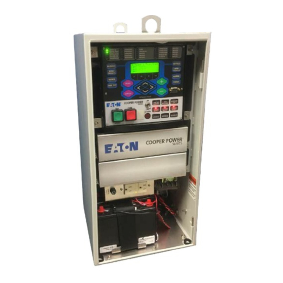
Form 6-LS Microprocessor-Based
Pole Mount Recloser Control
Installation and Operation Instructions
For Type F6-PA-LS Control
and Type F6-PB-LS Control.
• F6-PA-LS applies to Form 6-LS
control for use with W, VS, and
auxiliary-powered NOVA reclosers.
• F6-PB-LS applies to Control-Powered
NOVA Form 6-LS control for use with
control-powered reclosers.
Figure 1.
Form 6-LS microprocessor-based pole-mount recloser control.
Contents
Safety Information ..................................................... 2
Product Information .................................................. 3
Introduction ............................................................ 3
ANSI Standards ..................................................... 3
Quality Standards ................................................... 3
Acceptance and Initial Inspection ........................... 3
Handling and Storage ............................................ 3
Control Power ........................................................ 3
Battery Replacement and Disposal ........................ 3
Operation Upon Loss of AC Power ........................ 4
Form 6-LS Recloser Control Description ................. 4
Description ............................................................. 4
Theory of Operation ............................................... 5
Control Front Panel ................................................ 6
Control Features ..................................................... 12
Communications .................................................... 15
Control Information ................................................. 15
Control Back Panel ................................................ 15
Installation Procedure ............................................... 16
Initial Programming Prior to Installation ................... 16
Control / Recloser Compatibility ............................. 16
Duty Cycle Monitor ................................................. 17
Control Cable ......................................................... 17
Mounting the Control .............................................. 18
Locking the Control ................................................ 18
Grounding the Control ............................................ 18
October 2012 • Supersedes 10/04
S280-70-10
Customer Connections for AC Power .................... 22
Using Removable Inserts ........................................ 32
Accessories ............................................................... 33
Loop Sectionalizing Accessories ............................ 33
120 VAC GFI Duplex Outlet .................................... 33
Discrete Interface Board Option Accessory ............ 33
Cabinet Ordering Accessories ................................ 33
Cable Locking Sleeves ........................................... 33
Radio Mounting Accessory ..................................... 34
Communication Board Accessories ........................ 35
Testing ........................................................................ 36
Testing an Installed Control .................................... 36
Remove the Control from Service ........................... 37
Preliminary Testing with No AC Available ................ 38
Testing with Type MET Tester ................................. 38
Closing the Recloser During Testing ....................... 39
Battery Test and Charging Procedures ................... 42
Return the Control to Service ................................. 44
Recloser VTC Interface ............................................. 45
Control VTC Interface ............................................... 46
Additional Information ............................................... 47
Replacement Kits ................................................... 47
Factory-Authorized Service Centers ....................... 47
Factory Maintenance Classes ................................. 47
Service Information
1
1
Advertisement
Table of Contents

Related Manuals for Cooper F6-PA-LS


Summary of Contents for Cooper F6-PA-LS
-
Page 1: Table Of Contents
Reclosers Service Information Form 6-LS Microprocessor-Based S280-70-10 Pole Mount Recloser Control Installation and Operation Instructions For Type F6-PA-LS Control and Type F6-PB-LS Control. • F6-PA-LS applies to Form 6-LS control for use with W, VS, and auxiliary-powered NOVA reclosers. • F6-PB-LS applies to Control-Powered NOVA Form 6-LS control for use with control-powered reclosers. -
Page 2: Safety Information
Form 6-LS Pole Mount Recloser Control Installation and Operation Instructions SAFETY FOR LIFE Cooper Power Systems products meet or exceed all applicable industry standards relating to product safety. We actively promote safe practices in the use and maintenance of our products through our service literature, instructional training programs, and the continuous efforts of all Cooper Power Systems employees involved in product design, manufacture, marketing, and service. -
Page 3: Product Information
Note: When shipped from the factory, the battery source is Cooper Power Systems sales representative. disconnected and its output plugs are taped to the cabinet. Connect the battery plugs into the mating ANSI Standards connectors to complete the battery circuit. -
Page 4: Operation Upon Loss Of Ac Power
Form 6-LS Pole Mount Recloser Control Installation and Operation Instructions FORM 6-LS RECLOSER Operation Upon Loss of AC Power CONTROL DESCRIPTION The control is equipped with a 13 Amp-Hour 24 VDC lead acid battery for operation upon loss of AC power. The control maintains full operation from the battery for a period of time —... -
Page 5: Theory Of Operation
S280-70-10 The current for overcurrent protection is calculated on a sub-cycle basis; it includes only the fundamental and DC component. When the phase or ground current exceeds its pro- grammed minimum-trip value and associated time-cur- rent-curve (TCC) timing, the control initiates the pro- grammed sequence of recloser tripping and reclosing operations via the CPU and RIF modules. -
Page 6: Control Front Panel
Form 6-LS Pole Mount Recloser Control Installation and Operation Instructions Control Front Panel Front Panel Text Messaging The LCD messages are accessed from the front panel by The Form 6-LS control front panel is illustrated in Figure 4. following the Text Messages menu path. This menu The front panel is separated into two clearly identified, displays any active user-configured text messages. - Page 7 S280-70-10 Programming Panel LCD Display The LCD Display is a backlit 4-line, 20-character display The Programming panel has the following sections: that provides extensive distribution system, recloser, and One-Touch Analysis Keys control status information using a minimum of eight naviga- tion keypads (Figure 5).
- Page 8 Form 6-LS Pole Mount Recloser Control Installation and Operation Instructions Status Indicator LEDs CONTROL POWER: The green LED indicates there is adequate VTC voltage to trip the recloser. This LED does The status indicator LEDs (Figure 6) in the Programming not indicate the presence of AC or battery power.
- Page 9 S280-70-10 TIE: The red LED indicates the control is in tie mode and FREQUENCY TRIP: Indicates the recloser tripped due to will respond to voltage conditions on Source I and/or an under or over frequency condition. Source II. VOLTAGE TRIP: Indicates the recloser tripped due to an SECTIONALIZER: The red LED indicates the control is in under or over voltage condition.
- Page 10 Form 6-LS Pole Mount Recloser Control Installation and Operation Instructions HOT LINE TAG ON/OFF Toggle Switch and LED Indicator WARNING: Hazardous voltage. Do not use Hot F6 RECLOSER CONTROL Line Tag as a substitute for a visible disconnect. TRIP CLOSE Always establish a visible disconnect prior to performing CLOSE any work requiring a de-energized line.
- Page 11 S280-70-10 One-Touch Function Keys SUPERVISORY OFF Quick access to frequently operated Form 6-LS control When the SUPERVISORY OFF red indicator is illuminated, features is provided with nine function key pushbuttons on supervisory commands are blocked. Supervisory functions the control operator panel. through the back panel serial communication ports and the discrete I/O are blocked.
-
Page 12: Control Features
Form 6-LS Pole Mount Recloser Control Installation and Operation Instructions Control Features Sequence Coordination Sequence Coordination eliminates nuisance tripping The Form 6-LS recloser control offers numerous standard through trip coordination. It allows the control to step features and accessories that allow the user the utmost through selected operations in the operating sequence flexibility applying the recloser control. - Page 13 S280-70-10 Metering The control also provides a minimum of three configurable input control contacts. Each control contact is configurable The control provides instantaneous and/or demand using a graphical interface software. Contacts accept a metering with programmable integration intervals for the whetting voltage range of 12–250 VDC, 120/240 VAC.
- Page 14 1 T. Takagi, Y. Yamakoshi, J. Baba, K. Uemura, T. Sakaguchi, "A New following default address: Algorithm of an Accurate Fault Location for EHV/UHV Transmission Lines: Part I - Fourier Transformation Method", IEEE Trans. on PAS, Vol. PAS- C:\Program Files\Cooper\ProviewXX\Form6\Form 6 100, No. 3, March 1981, pp 1316-1323. Inserts.doc Sync Check...
-
Page 15: Communications
S280-70-10 Communications Ethernet configuration is accomplished via ProView inter- face software. Refer to Service Information S280-70-4 Communication Ports (ProView 4.X.X) or S280-70-21 (ProView 5.X.X) Form 6 Programming Guide , Section Schemes, The Form 6 control has two back panel communication Communicating with the Form 6 Control, for Ethernet ports and a front panel configuration data port. -
Page 16: Installation Procedure
Reclosers equipped with Type B sensing CTs are functions and programming parameters required for the compatible with all Cooper Power Systems recloser specific recloser installation. controls (Form 2, Form 3, Form 3A, Form 4A, Form 4C,... -
Page 17: Duty Cycle Monitor
S280-70-10 Duty Cycle Monitor TABLE 1 Serial Number Break for Reclosers with Type A The Duty Cycle Monitor provides the following duty cycle Sensing CTs information: Recloser Below Serial Number • Measures and records duty for each individual phase in 5831 non-volatile memory. -
Page 18: Mounting The Control
Form 6-LS Pole Mount Recloser Control Installation and Operation Instructions Mounting the Control Grounding the Control WARNING: This equipment is not intended to WARNING: Hazardous voltage. Recloser and protect human life. Follow all locally approved control must be solidly grounded. Follow all procedures and safety practices when installing or locally approved procedures and safety practices when operating this equipment. - Page 19 S280-70-10 SHACKLE DIAMETER .177-295" SHACKLE DIAMETER .295-.394" Note: DO NOT use a smaller shackle (.177- .295) in the larger diameter hole as it will NOT LOCK the cabinet. (1.25) 16 (.63) Dia. (12.25) Mounting Holes (2) RS-232 Lifting CONTROL OK A PHASE FAULT ALARM A PHASE VOLTAGE...
- Page 20 Form 6-LS Pole Mount Recloser Control Installation and Operation Instructions Grounding with a Local Supply Voltage Transformer; 4-Wire Multi-Grounded Installation of a Form 6-LS pole mount recloser control 4-Wire Multi-Grounded Systems with a local supply voltage transformer must include the following: IMPORTANT: In pole-mounted applications, a ground connection must be made between the recloser,...
- Page 21 S280-70-10 Grounding with a Remote Supply Voltage Transformer; 4-Wire Multi-Grounded IMPORTANT: In pole-mounted applications, a ground Installation of a Form 6-LS pole mount recloser control connection must be made between the recloser, with a remote supply voltage transformer must include the transformer, recloser control, and SCADA equipment following: for proper protection of the equipment.
-
Page 22: Customer Connections For Ac Power
Form 6-LS Pole Mount Recloser Control Installation and Operation Instructions Customer Connections for AC power supply accessory is available for communication equipment rated for 13.8 VDC. Refer to Radio Mounting Power to Form 6-LS Control Accessory in the Accessories section of this manual for additional information regarding the radio power supply. - Page 23 S280-70-10 Figure 14. Default factory wiring (transfer relay connections) connected to B-Phase voltage metering with B-Phase incoming supply.
- Page 24 Form 6-LS Pole Mount Recloser Control Installation and Operation Instructions Figure 15. Typical tie application with junction box accessory. Six single-phase Transformer Connection, Wye configuration only (TB8 Terminal Block Connection).
- Page 25 S280-70-10 Figure 16. Typical sectionalizer application, no junction box. Three-Phase Transformer Connection, Wye configuration only (TB8 Terminal Block Connection).
- Page 26 Form 6-LS Pole Mount Recloser Control Installation and Operation Instructions Standard Default Supervisory Input TABLE 4 Control and Output Status Contacts Operating Current Requirements for Standard and Optional Supervisory Inputs Standard customer connections TB1 and accessory customer connections are TB3 and TB4. Refer to Figures Nominal Minimum 17 and 18 and Tables 4, 5, and 6.
- Page 27 S280-70-10 IMPORTANT Shielding and Surge Protection of Supervisory Cables All supervisory operation and control monitor leads must be protected within shielded cables. Refer to Figure 19. NOTICE: External leads must be shielded and the shield must be grounded at both ends. Terminate each lead with a 320VAC, 150 Joules metal oxide varistor (MOV), or equivalent, at the remote end.
- Page 28 Form 6-LS Pole Mount Recloser Control Installation and Operation Instructions Figure 18. Form 6-LS control Discrete Interface Board accessory default supervisory input control and output status con- tacts.
- Page 29 S280-70-10 FORM 6-LS CONTROL SHIELD Customer Wiring 28 VDC Whetting Voltage Terminals Factory-Supplied 28 VDC Whetting Voltage — Customer Wiring REMOTE Supervisory Trip and Lockout Supervisory Close Remote Trip and Lockout Recloser 12 CO1 Status *Contacts shown with recloser in OPEN position.
- Page 30 Form 6-LS Pole Mount Recloser Control Installation and Operation Instructions Rear Panel RS-232 Communication Port Pin Assignments RS-232 Serial IRIG-B Time Tables 7 indicates the pin assignments for the rear panel Communication Port Sync Connector RS-232 communication port (Figure 20). Refer to Figure 21 for pin identification.
-
Page 31: Before Placing Control And Recloser Into Service
S280-70-10 Before Placing the Control and the D. Press the F4 button to test the battery. Recloser into Service Note: This message will appear on the programming panel LCD display: ----TESTING---- CAUTION: Equipment misoperation. Do not The battery test results will display in the battery connect this control to an energized recloser until metering menu. -
Page 32: Using Removable Inserts
T253.1 C: \ Program Files \ Cooper \ ProviewXX \ Form 6 \ Form 6 Inserts.doc The front panel inserts can be changed, if desired. IMPORTANT: Laminate the removable inserts prior to 1. -
Page 33: Accessories
S280-70-10 ACCESSORIES Cable Locking Sleeves These accessories are available. Contact your Cooper Power Systems representative for additional information. To prevent detachment of the control cable from the con- trol cabinet by unauthorized personnel, a cable-locking Loop Sectionalizing Accessories sleeve is available to enclose the cable plug. The plug is... -
Page 34: Radio Mounting Accessory
40 Watts (peak) and is fused to isolate any potential radio problems without disturbing the protection system in the recloser control. Refer to Table 9. Contact your Cooper Power Systems representative for any additional voltage requirements. C + – RS-485... -
Page 35: Communication Board Accessories
2000m with 62.5/125µm multi-mode fiber. Consult (RTU), wireless, telephone modem, Ethernet network, or your Cooper Power Systems representative for availability other communication devices. The following options are of long haul solutions. Link communication speed is con-... -
Page 36: Testing
Form 6-LS Pole Mount Recloser Control Installation and Operation Instructions Standard (No Communication Option) RS-485 Communication Serial Fiber RS-485 C NON-ECHO IRIG-B IRIG-B IRIG-B Default J4 – ETHERNET – J3 J4 – ETHERNET – J3 J4 – ETHERNET – J3 J4 –... -
Page 37: Remove The Control From Service
S280-70-10 Remove the Control from Service LCD Display METERING SETTINGS IIMPORTANT: Disconnect switches for AC sensing RESET OPER COUNTER TARGETS and power connections are necessary to isolate the LAMP TEST Key Form 6 control for testing and servicing. EVENTS ALARMS MENU LAMP TEST CHANGE... -
Page 38: Preliminary Testing With No Ac Available
Form 6-LS Pole Mount Recloser Control Installation and Operation Instructions Preliminary Testing with No AC Testing with Type MET Tester Available The Type MET electronic recloser control tester (Figure 31) is used for testing the following functions of the Form 6 If the Form 6 control is not in service and requires recloser control: energization for preliminary testing, it can be powered up... -
Page 39: Closing The Recloser During Testing
S280-70-10 Closing the Recloser During to the voltage rating of an available power source, and a high-side rating equal to the voltage rating of the recloser Testing (Figure 34). A 75 kVA transformer of the proper voltage rat- ing with an impedance drop of approximately 3% is satis- Electrical Closing –... - Page 40 Form 6-LS Pole Mount Recloser Control Installation and Operation Instructions Electrical Closing – Motor-Operated Low Voltage Closing Solenoid / NOVA Variable 115Vac Reclosers Autotransformer (10 Amp) 600:5 Recloser WARNING: Hazardous voltage. Solidly ground BCT ON 600:5 Tap all equipment. Failure to comply can result in death, severe personal injury, and equipment damage.
- Page 41 S280-70-10 Manual Closing – Solenoid-Operated SENSING CTs (3) Reclosers WARNING: Explosion Hazard. Excessive Contact Arcing. Do not use the manual closing tool to close an oil-insulated energized recloser. Closing an energized oil-insulated recloser with a manual clos- ing tool can cause excessive contact arcing, rapid build-up of gas within the equipment, and possible NOT APPLICABLE FOR explosion which can cause death, severe personal...
-
Page 42: Battery Test And Charging Procedures
Form 6-LS Pole Mount Recloser Control Installation and Operation Instructions Battery Test and Charging Test Procedure for Uninstalled Battery Procedures The entire process should be conducted in a clean environment, such as a repair shop. Test Procedure for Installed Battery Refer to Table 11 and follow this procedure to perform a Follow the procedure below to perform a battery test in the bench test on a control battery in a service shop:... - Page 43 S280-70-10 Battery Charging The charger senses when the battery voltage reaches 2.27 volts per cell, then the charge rate reduces to maintain a If it is not possible to charge the battery with the control’s trickle charge. built-in charger, a KME5-60-1 (120 VAC) portable bench The yellow LED flickers to indicate the battery has reached type battery charger kit is available, which includes the a full charge.
-
Page 44: Return The Control To Service
Form 6-LS Pole Mount Recloser Control Installation and Operation Instructions Return the Control to Service • In the SECTIONALIZING mode, once voltage is restored, the LS is disabled until locally or remotely enabled. The control remains in the present state CAUTION: Equipment misoperation. -
Page 45: Recloser Vtc Interface
S280-70-10 RECLOSER VTC INTERFACE Control-Powered Type NOVA reclosers with serial numbers 100,000 and above, as listed in Table 13, require a VTC- ready control. They are equipped with a 19-pin control cable receptacle and can be identified by labels prominently displayed on the bottom of the recloser tank and on the side near the 19-pin receptacle, as shown in Figure 38. -
Page 46: Control Vtc Interface
Form 4C recloser VTC-ready, contact your Cooper Power Figure 39. Systems representative. -
Page 47: Additional Information
MET Electronic Recloser Control Tester Operation and kits, refer to the Replacement Parts price list for catalog Testing Procedures is available as a supplemental training numbers and pricing. Contact your Cooper Power Systems aid for service personnel. representative for additional information and order procedures. - Page 48 All Cooper logos, Cooper Power Systems, Kyle, ProView, Idea Workbench, Communications Workbench, and TCC Editor are trade- marks of Cooper Industries in the U.S. and other countries. You are not permitted to use Cooper trademarks without the prior written consent of Cooper Industries.
Need help?
Do you have a question about the F6-PA-LS and is the answer not in the manual?
Questions and answers