Table of Contents
Advertisement
Quick Links
Installation Guide
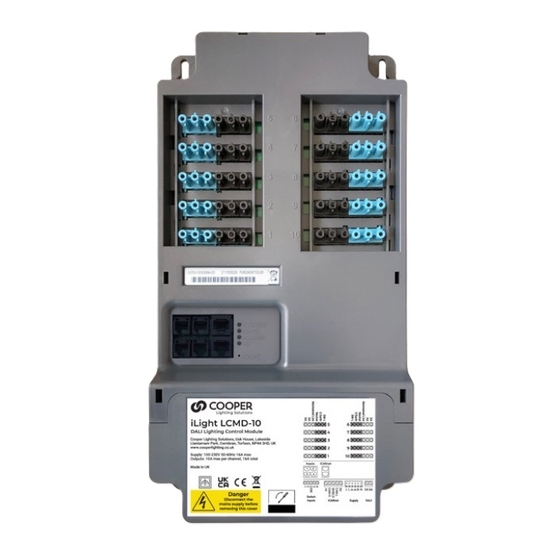
LCMD-10
DALI Lighting Control Module
Mounting & Installation
LCMD-10 must be securely mounted to a suitable surface using the 4 mounting holes provided with fixings
suitable for the substrate (Maximum fixing diameter 6mm). The LCM can be mounted in any orientation to
cable trays, walls and direct to a ceiling slab. All cables should be independantly secured with appropriate
fixing straps in accordance with local electrical regulations. Incoming mains, data and input cables should
be installed using suitable compression cable glands to provide strain relief.
Mounting Hole
350mm Hole Centres
Mounting Hole
Cooper Lighting Solutions
Usk House, Lakeside
Llantarnam Park,
Cwmbran,
NP44 3HD, UK
t: +44 (0)1923 495495
e: info@cooperlightingsolutions.co.uk
www.cooperlightingsolutions.co.uk
EU Authorised Representative
Cooper Lighting Netherlands B.V.
High Tech Campus
HTC 48
Eindhoven
5656 AE
E&OE. iLight reserve the
right to make changes to the
equipment without prior notice.
© Cooper Lighting Solutions
Doc No: 9850-000754-01
FM 664349
Mounting Hole
Once securely mounted,
remove cover using a
flat-head screwdriver
to access the wiring
compartment. Gently tilt
the screwdriver towards
the top (connectors) of
LCM to release.
Mounting Hole
Typical Schematic
DALI
Emergency Luminaire
Drivers / Ballasts
LCMD-10
Removing Knockouts
The knockouts can be removed with a flat-head
screwdriver in 2 simple steps:
1. Place the flat-head screwdriver into the slot of the
knockout that is to be removed. The screwdriver must be
placed in the slot nearest to the bottom of the enclosure
(opposite the cover).
2. Hit the end of the screwdriver to shear the knockout and
remove the rest of the knockout by hand if necessary.
Alternatively an appropriate sized hole saw can be used
utilising the drill bit location point at the centre of each
knockout.
DALI
DALI
High Bay Sensor
Control Plate
DALI
DALI
DALI
Control Plate
Combined Sensor
230V Supply
Third Party
Light Switch
Key Switch
iCAN Network
Technical Data
Electrical Data
Supply: 230 volts -/+ 10%, 50/60 Hz
Terminals max. wire size: 4mm
2
loop in/out
iCANnet™ inputs/output: 5 pole Phoenix connector
Maximum DALI cable length: 300m per LCM
Minimum DALI cable conductor diameter: 1.5mm
Protection: Provided by installer - Max 16A
DALI signal: Nominal 16V, max current 200mA supply.
Guaranteed minimum current 150mA
Automatic shut-down and restart after short-circuit
(maximum 1 per bus) according to IEC 62386-101
Inputs & Outputs
10 ports with 6 pole GST/18 connectors
4 x RJ12 analogue sensor inputs
Max 30 DALI luminaires (or short addresses) distributed at will
across 10 ports
In addition: 1 DALI sensors per port,
1 DALI control plate or DALI-I-U per port
1 DALI emergency luminaire per port
Mechanical Data
Dimensions: 200.2mm (w) x 382.8mm (h) x 57.5mm (d)
Maximum diameter of fixings: 6mm
Weight: 2.5 kg
Operating Conditions
Operating temperature: +2ºC to +50ºC
Max storage temperature: +60ºC
Humidity: +5 to 95% non-condensing
Environmental protection: IP20
2
Advertisement
Table of Contents

Subscribe to Our Youtube Channel
Related Manuals for Cooper LCMD-10


Summary of Contents for Cooper LCMD-10
- Page 1 Mounting & Installation Technical Data Electrical Data LCMD-10 must be securely mounted to a suitable surface using the 4 mounting holes provided with fixings Removing Knockouts Supply: 230 volts -/+ 10%, 50/60 Hz suitable for the substrate (Maximum fixing diameter 6mm). The LCM can be mounted in any orientation to The knockouts can be removed with a flat-head Terminals max.
- Page 2 Green LED flashes – device OK Provided by installer (16A Max) electrician to the local/national regulations. LCMD-10 does not provide a protective earth. Data LED Red LED flashes when messages sent on network...
Need help?
Do you have a question about the LCMD-10 and is the answer not in the manual?
Questions and answers