
Subscribe to Our Youtube Channel
Related Manuals for Orno OR-VID-CK-1039


Summary of Contents for Orno OR-VID-CK-1039
- Page 1 Video Door Entry System Kits 4 Wires Installation Safety & Operating Instructions OR-VID-CK-1039...
-
Page 2: Fittings Supplied
These instructions are for your safety. Please read through them thoroughly before use and retain for future reference. Parts Supplied Fittings Supplied Description Illustration Description Illustration Power cover Indoor Monitor Locker Bracket Holder Screw B1 Screw B2 Outdoor Camera Screw B3 Scew B4 Wall mounting... -
Page 3: Technical Characteristics
Technical Characteristics Indoor Unit (NVM-904) Specifications Dimensions 200[W] x145 [H] x23 [D] mm Weight 0.5Kg Input Power DC15V (External Power Supply) Power Consumption Idle mode : 2W Operating : Max 14W Connecting System 4 wires; 2 Cameras, 2 Monitors Voice transmission Half duplex two way communication Call sound Chime sound... -
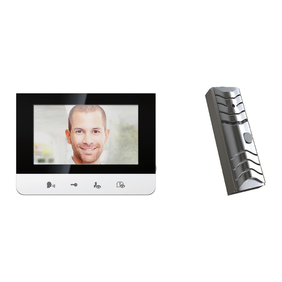
Page 4: Indoor Unit
Indoor unit 1. Monitor screen 2. Talk on/Talk off (Monitor off) 3. Door lock Open 4. Camera 1 / Camera 2 5. Intercom 6. Gate Open 7. Microphone 8. Menu Select(Brightness,Contrast,Color) 9. Down 10.Up 11.Ring Sound volume Outdoor unit 1. Microphone 2. -
Page 5: Safety Instructions
Safety Instructions 1. Do not install near other electronic equipment such as computers, TV, video recorder as this may cause radiated interference to the unit. 2. Do not disassemble the unit. 3. Do not spray water on the indoor unit. Do not keep the outdoor unit where it will be exposed to extreme moisture. - Page 6 WIRING DIAGRAM ONE-FAMILY SYSTEM WITH ONE MONITOR AND ONE CAMERA Page...
- Page 7 WIRING DIAGRAM ONE-FAMILY SYSTEM WITH TWO MONITORS AND TWO CAMERAS Page...
- Page 8 A) Cable connection 1. Connect the monitor to the camera with the cable according to the wiring diagram. 2. Carefully insert the wires to the terminal by pressing down the terminal flap with any small tool taking care that the 2 bare wires do not touch. B) Installation height 1.
- Page 9 2. Carefully place the indoor monitor against the bracket and gently push down the monitor so that the pins on the bracket engage in the slots on the rear of the monitor. 3. Secure the assembly with the 2 screws. Only after having connected the roadside panel,connect the 230 V~ power supply to the adapter.
- Page 10 Option 2 (Without angle bracket) 1) Screw the raishield to the wall by 1 screw (Screw B1) (Fig.1) 2) Connect all the wires & install the door panel inside the rainshield (Fig. 2) 3) Fix the door panel inside the rainshield by the screw (Screw B4) (Fig. 3) 4) Install the cap and fix it tightly (Fig.
-
Page 11: Performance Settings
E) Installation of the transformer Attach the transformer to a DIN rail in a modular fusebox or to a flat surface using the two black lugs clipped to the sides of the power supply. Performance Settings You can adjust the brightness,contrast and colour of the monitor when it is ON by pressing the Menu button at the side of the monitor. - Page 12 c) Monitor time: Approximately 30 seconds When outside camera is activated from the inside,there is approximately 30 seconds of viewing time before the unit automatically shuts off. 4. Activation of “Intercom” button An intercom calling can be started by any indoor monitor. When the intercom button on one indoor monitor is touched, this will ring all monitors in a system,you can talk with the one calling monitor by touching the...
-
Page 13: Troubleshooting
Care and Maintenance Do not store in hot or cold areas. Extreme hot or cold temperatures can shorten the life of electronic devices and can distort/melt certain plastics or may cause malfunction. Dropping can result in failure to operate. Circuit boards can crack and may not ...
Need help?
Do you have a question about the OR-VID-CK-1039 and is the answer not in the manual?
Questions and answers