
Related Manuals for Orno Gayd


Summary of Contents for Orno Gayd
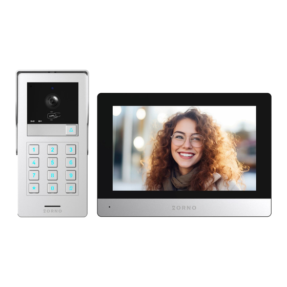
- Page 1 Operating and installation instructions Video doorphone set Gayd OR-VID-MA-1080/B OR-VID-MA-1081/B OR-VID-MA-1082/B instruction manual STOP! ARE NOT SUBJECT TO REPAIR UNDER WARRANTY!
-
Page 2: Table Of Contents
TABLE OF CONTENTS 1. SAFETY INSTRUCTIONS ..................................3 2. CHARACTERISTICS OF THE SET ..............................4 3. TECHNICAL DATA ....................................4 4. SET CONSTRUCTION ..................................5 5. INSTALLATION ....................................6 MONITOR INSTALLATION ....................................6 OUTDOOR UNIT WITH CAMERA INSTALLATION ............................6 6. -
Page 3: Safety Instructions
Additional information about ORNO products is available at www.orno.pl. Orno-Logistic Sp. z o.o. holds no responsibility for the results of non-compliance with the provisions of the present Manual Orno-Logistic Sp. z o.o. reserves the right to make changes to the Manual - the latest version of the Manual can be downloaded from www.orno.pl Any translation/ interpretation rights and copyright in relation to this Manual are reserved. -
Page 4: Characteristics Of The Set
2. CHARACTERISTICS OF THE SET The videodoorphone is designed for installation in 1-family (OR-VID-MA-1080), 2-family (OR-VID-MA-1081) and 4-family (OR-VID-MA-1082) buildings. Functions: - simultaneous view and hold of a conversation with a person in front of an entrance; - direct control of an electric door strike; - two gate control (e.g., entrance and garage gate);... -
Page 5: Set Construction
OUTDOOR UNIT SENSOR TYPE: CMOS 1/2.9’ RESOLUTION: 2MP, 1920x1080, 1080p VIEWING ANGLE (VERTICAL/HORIZONTAL): 52° / 105° NIGHT LIGHTING: IR diodes NUMBER OF DIODES: NIGHT VISION RANGE: approx. 1m RFID READER: 125kHz RFID-tags/cards (max. 200 users) CODELOCK: yes, backlit buttons (applies to OR-VID-MA-1080 and OR-VID-MA-1081) MOTION SENSOR: INGRESS PROTECTION: IP65... -
Page 6: Installation
5. INSTALLATION MONITOR INSTALLATION . 3 Monitor installation. 1. Drill holes in the wall and insert wall anchors into them 2. Screw the monitor mounting bracket to the wall with screws. 3. Connect the wires to the monitor and hang it on the mounting bracket. 4. - Page 7 . 5 Outdoor unit with camera surface installation. 1. Drill holes in the wall and insert the wall anchors into them. 2. Screw the rainshield to the mounting frame with one screw. 3. Attach the mounting frame of the outdoor unit in desired place using four screws. 4.
-
Page 8: Wiring Diagrams
6. WIRING DIAGRAMS Before drilling the installation holes, it is recommended to carry out a functional test of the device. To do this, connect the device for a test according to the wiring diagram. The first person holding the camera should use the button to call the second person who is at the monitor. - Page 9 . 9 Four-family set wiring diagram. . 10 Monitors and outdoor units wiring diagram. Description of the monitor connection terminals: Rj45 – Internet network connection terminal, IN/OUT – connection terminals of outdoor unit or additional monitor, Power – 24V DC power supply terminal (optional), BELL –...
- Page 10 . 11 Monitor and outdoor unit wiring diagram. . 12 Gate, electric door strike, and exit button wiring scheme. It is forbidden to make connections to live equipment! Failure to adhere to this recommendation may result in permanent damage to the device and loss of health. The set does not include an electric door strike and automatic gate control unit! The video doorphone cables should not be routed in one cable with the cables of other installations such as bell, alarm, etc.
-
Page 11: Set Operation
7. SET OPERATION MAIN MENU Intercom Intercom function available with additional monitors connected – tap to select the monitor you want to connect to. Monitor selection screen: Call screen: 1 Select the monitor you want to connect to, 2 Return to the previous page, 3 ID of the monitor you are connecting to, 4 ID of the monitor you are using, 5 Call button - tap to connect to the selected monitor. -
Page 12: Outdoor Unit Monitoring
OUTDOOR UNIT MONITORING Monitoring After tapping the icon in the main menu or while connected to an outdoor unit, the outdoor camera view screen will be displayed. The maximum monitoring and call time is 30 seconds and the maximum call and conversation time is 120 seconds. -
Page 13: Ip Camera Monitoring
IP CAMERA MONITORING After switching to IP camera view, the image from the selected camera will be displayed. The maximum monitoring time is 30 seconds. During the monitoring, you can save a video recording (requires a microSD card). Note: this function is only available when an IP camera is connected. -
Page 14: Connection And Conversation
CONNECTION AND CONVERSATION call 1. When the button on the outdoor unit is pressed, the monitor rings and the image from the external camera is displayed on the screen. The ringing time is max. 30 seconds. 2. When the answer call button is tapped, the conversation can be started. -
Page 15: Settings
The name contains the date and time the file was saved (year/month/day-hour/ File name minute/second-source/mode/format, see page 10 RECORDINGS AND MEMORY Register icon Displays the icon of the selected catalogue. Source Displays the source from which the image/video recording was saved. Tap the chosen file name to open the actions menu: Open –... -
Page 16: System Settings
Network Tap to enter the network settings and configure the device with Wi-Fi. Scene Tap to enter the digital frame settings. Advanced Tap to enter the advanced settings. System info Tap to open the system information tab. Back Tap to return to the previous page. SYSTEM SETTINGS Displays the ID number of the current monitor. -
Page 17: Administrator Settings
ADMINISTRATOR SETTINGS Configure the family number of the selected monitor (applies to multifamily models). Room number Assign the appropriate numbers to the monitors (1-2 in OR-VID-MA-1081 or 1-4 in OR- VID-MA-1082) so that each corresponds to a separate call button. Displays the IP address of the device. -
Page 18: Password Management
Select what can be opened by the selected proximity card/tag (lock - releases the Access electric strike, gate1 - controls the opening/closing of the gate). Tap the chosen card number to open the actions menu: Delete – removes the selected proximity card/tag, Actions Delete all –... -
Page 19: Outdoor Unit Settings
OUTDOOR UNIT SETTINGS Door After tapping the icon in the settings menu, the outdoor unit settings menu will be displayed. Status Turn the outdoor unit on or off from the level of the monitor. Lock unlock time Door/wicket opening settings (1-10s). Gate unlock time Gate opening settings (1-10s). -
Page 20: Ip Camera Settings
IP CAMERA SETTINGS Camera After tapping the icon in the settings menu, the IP camera settings menu will be displayed. To configure an IP 9. IP CAMERA CONNECTION camera, go to section Enable Turn the IP camera on or off from the level of the monitor. Model Select the model of your IP camera to complete the configuration. -
Page 21: Digital Frame Settings
Network information Display the information of the network to which the device is connected. Kod QR Display a QR code to pair the device with the Tuya Smart mobile app. �� To use the Tuya Smart app with a wired connection: 1. -
Page 22: Advanced Settings
ADVANCED SETTINGS Advanced After tapping the icon in the settings menu, the advanced settings menu will be displayed. Tap to format the SD card. After adding a new SD card to the device, it is recommended Format SD card to format it before further use. Tap to restore the factory settings of the monitor. -
Page 23: Ip Camera Connection
9. IP CAMERA CONNECTION WIRED CONNECTION Note: make sure the IP camera you want to connect supports the ONVIF protocol. 1. Connect the IP camera to the router using a Cat.5e network cable, and then connect the computer to the same router. Make sure the camera and the computer are on the same subnet. -
Page 24: Wireless Connection
WIRELESS CONNECTION Note: make sure the IP camera you want to connect supports the ONVIF protocol and has the function of wireless connection via Wi-Fi. 1. Configure the wireless IP camera according to the instructions of the chosen camera. Be sure to enable the ONFIV protocol in the configuration panel. -
Page 25: Mobile App Installation
10. MOBILE APP INSTALLATION LOGIN Note: a device can only be paired with one Tuya account. To pair the device with a new account, remove the pairing with the previous account or use the share function in the app to make the device available for a second account. 1. - Page 26 Add device Scan 2. In the app on your phone, click and then click the icon located in the upper right corner. Scan the QR code displayed on the monitor to start the process of pairing the device with your phone. 3.
-
Page 27: Inviting Users
INVITING USERS 1. Select the tab on the bottom bar of the app, then enter Home management>My Home . Here, give the family a name (e.g. the Smiths). Add members 2. Select . On the app screen, options of sharing the invitation code will appear (e.g. text message). Invited users can add their device by entering the invitation code in Home management>Join a home - once the app is... -
Page 28: Troubleshooting
Orno-Logistic Sp. z o.o. declares that the type of radio device OR-VID-MA-1080, OR-VID-MA-1081, OR-VID-MA-1082 Video doorphone set Gayd is compliant with the Directive 2014/53/EU. The full text of the EU declaration of conformity is available at the following web address: www.orno.pl...
Need help?
Do you have a question about the Gayd and is the answer not in the manual?
Questions and answers