
Related Manuals for Orno Naos RFID OR-VID-SH-1074


Summary of Contents for Orno Naos RFID OR-VID-SH-1074
- Page 1 Instrukcja obsługi i montażu Zestaw wideodomofonowy Naos RFID OR-VID-SH-1074 instrukcję obsługi STOP!
-
Page 2: Uwagi Wstępne
Orno-Logistic Sp. z o.o. nie ponosi odpowiedzialności za skutki wynikające z nieprzestrzegania zaleceń niniejszej instrukcji. Firma Orno-Logistic Sp. z o.o. zastrzega sobie prawo do wprowadzania zmian w instrukcji - aktualna wersja do pobrania ze strony www.orno.pl. Wszelkie prawa do tłumaczenia/ interpretowania oraz prawa autorskie niniejszej instrukcji są zastrzeżone. -
Page 3: Dane Techniczne
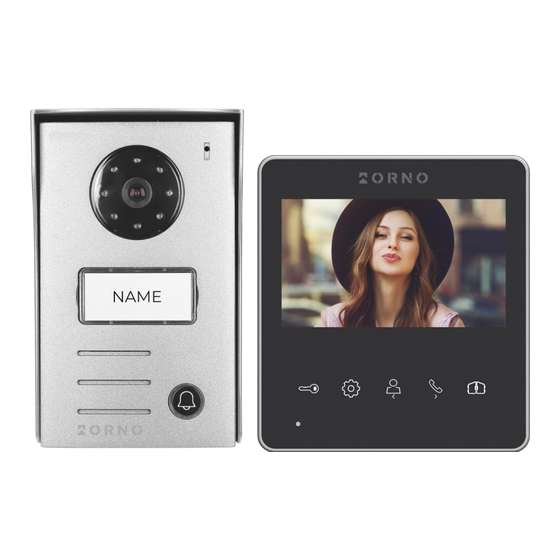
3. DANE TECHNICZNE TYP URZĄDZENIA: jednorodzinny SPOSÓB INSTALACJI: 2-żyłowy SYSTEM KOMUNIKACJI: przewodowy MONITOR WIELKOŚĆ EKRANU: 4,3” ROZDZIELCZOŚĆ: 480x272x3RGB FUNKCJE: rozmowa, monitoring, sterowanie elektrozaczepem i bramą, regulacja parametrów monitora oraz głośności, interkom ILOŚĆ MELODII: REGULACJA GŁOŚNOŚCI: 100s CZAS ROZMOWY: CZAS MONITORINGU: 15V DC ZASILANIE: czuwanie <2W;... - Page 4 4. BUDOWA ZESTAWU rys. 1 Budowa wideo monitora i panelu zewnętrznego MONITOR PANEL ZEWNĘTRZNY 1. Ekran 11. Mikrofon 2. Mikrofon 12. Obiektyw kamery 3. Otwarcie drzwi/furtki 13. Doświetlenie nocne 4. Ustawienia 14. Miejsce na nazwisko/czytnik kart i breloków 5. Zakończenie rozmowy/monitoringu/przycisk nawigacji - 15.
- Page 5 5. MONTAŻ MONTAŻ MONITORA rys. 2 Montaż monitora 1. Określ pozycję montażową monitora: sugerowana wysokość 1,5~1,6 metra; 2. Ramkę montażową odłącz od tylnej części monitora. 3. Zamontuj ramkę na ścianie. 4. Podłącz okablowanie, zgodnie z ze schematem podłączenia. 5. Przymocuj monitor do wspornika montażowego. 6.
- Page 6 6. SCHEMATY PODŁĄCZENIA Przed wykonaniem otworów montażowych zaleca się wykonać próbę działania urządzenia. W tym celu podłącz urządzenie na próbę wg. schematu podłączenia. Pierwsza osoba przytrzymująca kamerę powinna za pomocą przycisku wywołać drugą osobę, która znajduje się przy monitorze. Ta natomiast powinna dokładnie obejrzeć...
- Page 7 rys. 5 Schemat podłączenia z dodatkowym monitorem Zestaw nie zawiera elektrozaczepu oraz automatu sterowania bramą!
-
Page 8: Obsługa Urządzenia
Nie powinno się prowadzić przewodów wideodomofonu w jednym kablu z przewodami innych instalacji, np. dzwonka, alarmu, telefonu itp. Wszelkie przewody energetyczne i telekomunikacyjne emitujące silne pola magnetyczne (np. kolumny głośnikowe odbiornik telewizyjny) będące w bezpośrednim kontakcie z przewodami łączącymi panel zewnętrzny z monitorem i mogą... - Page 9 8. KORZYSTANIE Z CZYTNIKA KART I BRELOKÓW ZBLIŻENIOWYCH W skład zestawu wchodzą poniższe breloki: - pomarańczowy: brelok główny (1szt.) - szary: brelok użytkownika (4 szt.) - czarny: brelok kasowania (1 szt.) DODAWANIE UŻYTKOWNIKÓW 1. Zbliż brelok główny do czytnika na panelu zewnętrznym. Usłyszysz 3-krotny sygnał dźwiękowy, co będzie oznaczało wejście w tryb programowania.
-
Page 10: Czyszczenie I Konserwacja
ORNO-LOGISTIC Sp. z o.o. ul. Rolników 437, 44-141 Gliwice, Poland tel. (+48) 32 43 43 110, www.orno.pl NIP: 6351831853, REGON: 243244254... - Page 11 Operating and installation instructions Video doorphone set Naos RFID OR-VID-SH-1074...
-
Page 12: Table Of Contents
ORNO products is available at www.orno.pl. Orno-Logistic Sp. z o.o. holds no responsibility for the results of non-compliance with the provisions of the present Manual Orno Logistic Sp. z o.o. reserves the right to make changes to the Manual - the latest version of the Manual can be downloaded from www.orno.pl Any translation/ interpretation rights and copyright in relation to this Manual are reserved. -
Page 13: Technical Data
3. TECHNICAL DATA TYPE OF THE DEVICE: single family INSTALLATION METHOD: 2-wire COMMUNICATION SYSTEM: wired MONITOR SCREEN SIZE: 4,3” RESOLUTION: 480x272x3RGB FUNCTIONS: call, monitoring, door and gate control, monitor and volume control, intercom NUMBER OF MELODIES: VOLUME CONTROL: 100s CALL TIME: MONITORING TIME: 15V DC POWER SUPPLY:... -
Page 14: Set Construction
4. SET CONSTRUCTION fig. 1 Construction of the monitor and the outdoor unit MONITOR OUTDOOR UNIT 1. Screen 11. Microphone 2. Microphone 12. Camera lens 3. Door/wicket opening 13. Night-time lighting 4. Settings 14. Nameplate/RFID reader field 5. End call/monitor/navigation button - 15. -
Page 15: Monitor Installation
5. INSTALLATION MONITOR INSTALLATION fig. 2 Monitor installation 1. Specify the mounting position of the monitor: suggested height 1.5~1.6 meters; 2. Remove the mounting frame from the back of the monitor. 3. Mount the frame on the wall. 4. Connect the wiring according to the wiring diagram. 5. -
Page 16: Wiring Diagrams
6. WIRING DIAGRAMS Before drilling the installation holes, it is recommended to carry out a functional test of the device. To do this, connect the device for a test according to the wiring diagram. The first person holding the camera should use the button to call the second person who is at the monitor. - Page 17 fig. 5 Wiring diagram (with additional monitor) The set does not include an electric door strike and automatic gate control unit!
-
Page 18: Set Operation
The video doorphone cables should not be routed in one cable with the cables of other installations such as bell, alarm, etc. Any power and telecommunication cables emitting strong magnetic fields (e.g. loudspeaker columns, TV set) in direct contact with the cables connecting the outdoor unit to the monitor may adversely affect the operation of the set. If the user has other connection cables than the recommended ones, it is allowed to use them, however, it is necessary to make a test connection of the set in order to check its correct functioning. -
Page 19: Use Of The Proximity Card And Tag Readers
8. USE OF THE PROXIMITY CARD AND TAG READERS The set includes the following proximity tags: - orange: registration tag (1 pc.) - grey: user tag (4 pc.) - black: delete tag (1 pc.) ADDING USERS 1. Move the registration tag close to the reader on the outdoor unit. You will hear a triple beep, which will mean you entered the programming mode. -
Page 20: Cleaning And Maintenance
ORNO-LOGISTIC Sp. z o.o. ul. Rolników 437, 44-141 Gliwice, Poland tel. (+48) 32 43 43 110, www.orno.pl NIP: 6351831853, REGON: 243244254... - Page 21 Bedienungs- und Montageanleitung Video-Türsprechanlage Naos RFID OR-VID-SH-1074...
- Page 22 Internetseite www.orno.pl. Die Firma Orno-Logistic Sp. z o.o. haftet nicht für die Folgen der Nichteinhaltung der Empfehlungen, die in dieser Bedienungsanleitung zu finden sind. Die Firma Orno-Logistic Sp. z o.o. behält sich das Recht vor, Änderungen am Handbuch vorzunehmen - die aktuelle Version können Sie unter support.orno.pl heruntergeladen.
-
Page 23: Technische Daten
3. TECHNISCHE DATEN GERÄTETYP: Einfamilienhaus INSTALLATIONSMETHODE: 2-Draht KOMMUNIKATIONSSYSTEM: drahtgebundener MONITOR BILDSCHIRMGRÖßE: 4,3” AUFLÖSUNG: 480x272x3RGB EIGENSCHAFTEN: Gespräch, Überwachung, Tür- und Torsteuerung, Monitor- und Lautstärkeregelung, Interkom ANZAHL DER MELODIEN: LAUTSTÄRKEREGLER: 100s GESPRÄCHSZEIT: ÜBERWACHUNGSZEIT: 15V DC STROMVERSORGUNG: Standby <2W; Betrieb <3,5W STROMVERBRAUCH: KONTROLLE DES ELEKTRISCHEN TÜRÖFFNERS: ja (12V DC max. -
Page 24: Aufbau Des Sets
4. AUFBAU DES SETS Abb. 1 Aufbau des Monitors und der Außenstation mit Kamera MONITOR AUßENSTATION 1. Bildschirm 11. Mikrofon 2. Mikrofon 12. Kameraobjektiv 3. Öffnen der Tür/der Pforte 13. Nachtlicht 4. Einstellungen 14. Namensschild/RFID-Feld 5. Gespräch od. Monitoring beenden/Navigationstaste - 15. -
Page 25: Installation
5. INSTALLATION INSTALLATION DES MONITORS Abb. 2 Installation des Monitors 1. Geben Sie die Montageposition des Monitors an: vorgeschlagene Höhe 1,5~1,6 Meter. 2. Entfernen Sie den Montagerahmen von der Rückseite des Monitors. 3. Montieren Sie den Rahmen an der Wand. 4. -
Page 26: Verkabelungsdiagramm
6. VERKABELUNGSDIAGRAMM Es ist ratsam, den Betrieb des Geräts zu testen, bevor Sie die Befestigungslöcher bohren. Schließen Sie dazu das zu prüfende Gerät gemäß dem Schaltplan an. Die erste Person, die die Kamera hält, sollte mit der Taste die zweite Person anrufen, die am Monitor sitzt. Diese Person sollte das Sichtfeld der Kamera sorgfältig prüfen, um gegebenenfalls die Position des Moduls zu korrigieren. - Page 27 Abb. 5 Verkabelungsdiagramm mit zusätzlichem Monitor Ein elektrischer Türöffner und eine automatische Torsteuerung sind im Set nicht enthalten!
-
Page 28: Bedienung Des Gerätes
Es wird nicht empfohlen, die Drähte der Video-Türsprechanalge in einem Kabel mit den Leitungen anderer Anlagen zu verlegen, z. B. Klingel, Alarm, usw. Alle Strom- oder Telekommunikationsdrähte, die starke Magnetfelder aussenden (z. B. Lautsprecher, TV), die in direktem Kontakt mit den Drähten stehen, die die Außenstation mit dem Bildschirm verbinden, können den Betrieb des Geräts beeinträchtigen. -
Page 29: Verwendung Von Proximity Karten- Und Tag-Lesegeräten
8. VERWENDUNG VON PROXIMITY KARTEN- UND TAG-LESEGERÄT Die folgenden Tags sind enthalten: - orange: Registrierungs-Tag (x1) - grau: Benutzer-Tag (x4) - schwarz: Delete-Tag (x1) BENUTZER HINZUFÜGEN 1. Bewegen Sie das Registrierungs-Tag näher an den Leser auf der Außenstation. Sie hören einen dreimaligen Signalton, was bedeutet, dass Sie in den Programmiermodus eintreten. -
Page 30: Reinigung Und Wartung
5. Der elektrische Türöffner öffnet nicht jedes Mal a) Prüfen Sie den unabhängigen Betrieb des elektrischen Türöffners, indem Sie ihn an die erforderliche Spannung anschließen usw. ORNO-LOGISTIC Sp. z o.o. ul. Rolników 437, 44-141 Gliwice, Poland tel. (+48) 32 43 43 110, www.orno.pl NIP: 6351831853, REGON: 243244254...
Need help?
Do you have a question about the Naos RFID OR-VID-SH-1074 and is the answer not in the manual?
Questions and answers