
Related Manuals for Orno OR-VID-MO-1076


Summary of Contents for Orno OR-VID-MO-1076
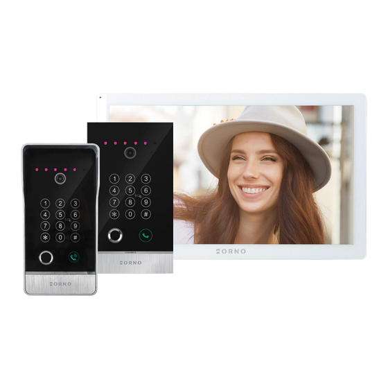
- Page 1 Operating and installation instructions Video doorphone set Guardo OR-VID-MO-1076 STOP!
-
Page 2: Table Of Contents
Additional information about ORNO products is available at www.orno.pl. Orno-Logistic Sp. z o.o. holds no responsibility for the results of non-compliance with the provisions of the present Manual Orno Logistic Sp. z o.o. reserves the right to make changes to the Manual - the latest version of the Manual can be downloaded from www.orno.pl Any translation/ interpretation rights and copyright in relation to this Manual are reserved. -
Page 3: Characteristics Of The Set
2. CHARACTERISTICS OF THE SET Videodoorphone is designed for installation in 1-family buildings. Functions: - talking to a person at the entrance and observing at the same time; - direct control of an electric door strike; - 3 access methods: using proximity cards and key tags, by reading a pre-entered fingerprint or by entering a PIN code on the illuminated keypad;... -
Page 4: Set Construction
OUTDOOR UNIT 4. SET CONSTRUCTION MONITOR 1. Microphone 2. LCD display 3. SD card slot 4. Loudspeaker 5. Power supply 6. Gate 7. Door 1 8. Door 2 9. Camera 1 10. Camera 2 11. Input from previous monitor 12. Output to another monitor... -
Page 5: Installation
OUTDOOR UNIT 22. Monitor connection 13. Camera illumination 23. Camera mode change button: 1080P-720P-CVBS 14. Camera lens 15. Numeric keypad 24. Settings button 16. Fingerprint reader 26. Door opening time adjustment (1-10sec.) 17. RFID reader field 27. Output for electric door strike (power supply from monitor 18. -
Page 6: Outdoor Unit With Camera Installation
OUTDOOR UNIT WITH CAMERA INSTALLATION fig.4 Outdoor unit placement Recommended installation height of the outdoor unit is 140-170cm. The correct location of the outdoor unit determines the comfort of working with the device. It is recommended to test the device before making mounting holes. Do not place the outdoor unit and monitor in the same room as feedback may occur. -
Page 7: Wiring Diagrams
6. WIRING DIAGRAMS Before drilling the installation holes, it is recommended to carry out a functional test of the device. To do this, connect the device for a test according to the wiring diagram. The first person holding the camera should use the button to call the second person who is at the monitor. - Page 8 fig. 8 Wiring diagram It is forbidden to make connections to live equipment! Failure to adhere to this recommendation may result in permanent damage to the device and loss of health.
- Page 9 fig. 9 Wiring diagram The set does not include an electric door strike and automatic gate control unit! The video doorphone cables should not be routed in one cable with the cables of other installations such as bell, alarm, etc. Any power and telecommunication cables emitting strong magnetic fields (e.g. loudspeaker columns, TV set) in direct contact with the cables connecting the outdoor unit to the monitor may adversely affect the operation of the set.
- Page 10 1. The distance between the outdoor unit and the monitor does not exceed 20 metres and a low-current electric door strike is used. 2. The distance between the outdoor unit and the monitor exceeds 20 metres. 3. Connection of a reversible electric door strike or electromagnetic jumper.
-
Page 11: Keypad Programming
The type of cable and its connection is shown below. (The correct operation of the device largely depends on the type of cable used). When designing the electrical installation, it is important to consider the appropriate cross-section of the wires: 1. -
Page 12: Factory Settings
8. FACTORY SETTINGS CHOICE OF LANGUAGE AND DEVICE ID Important: Assigning a device ID is an important part of the configuration in the system. For the whole set to function correctly, the device address configuration must be correct. If a particular monitor is connected to outdoor panel 1, the device address must be set to 1, while additional monitors must be set sequentially to 2/3/4/5/6. -
Page 13: Installing Applications
9. INSTALLING APPLICATIONS AP MODE To quickly configure the device, go to Settings> Network> Network Pairing Mode, select AP MODE and press return to restart the device. The Network Settings menu will display your WiFi network name and password. 1. Open the App Store (iOS) or Google Play (Android) on your phone. Search for the app "Tuya Smart" and install it or scan the QR code below: Tuya Smart 2. -
Page 14: Wifi Connection
WIFI CONNECTION 1. Log in to the app and go to the start page. Click the "+" icon in the top right corner or Add Device. 2. Select Camera and Lock. 3. Select Smart Doorbell. 4. Then select Wi-Fi Mode in the top right-hand corner. 5. - Page 15 9. Select SmartLife from the available networks. 10. Enter the password 12345678 and click Connect. 11. Wait for about a minute, the app screen will display Add Device. At the end of the process the app should display the message "Added successfully", click on the button "Done" in the top right corner. The video intercom is ready for use, check the quality of the connection by starting monitoring.
-
Page 16: Ez Mode
EZ MODE To quickly configure the device, go to Settings> Network> Network pairing mode, select EZ MODE and press return to restart the device. The Network Settings menu will display your WiFi network name and password. 6. Select EZ Mode. 7. -
Page 17: Application
10. APPLICATION Important: to ensure the correct functioning of the application, the user is obliged to update the application in accordance with communications from the application operator. Zoom in Full screen Take picture by App and save in mobile album Talk Take video by App and save in mobile album Playback video stored in SD card... -
Page 18: Menu
11. MENU An icon highlighted in red means that motion detection for a particular channel is enabled. Grey indicates that motion detection for a particular channel is disabled. 1: Mode: at home, normal operating status. The call on the outdoor unit will be redirected to the monitor and in the application. -
Page 19: Desktop
12. DESKTOP WINDOWS 10 ANDROID STANDARD... -
Page 20: Settings
13. SETTINGS SYSTEM SETTINGS 1. Formatting the SD card: Before formatting, copy the previously saved files on the SD card to the appropriate folder, note: the copied files must match the contents of the selected folder. 2. Restore factory settings: All set parameters will be restored to the default settings. Please remember to remove the device from the Tuya app as well before doing this, otherwise the device will not be able to be added and used by other accounts. -
Page 21: Ring
15. RING 1. The ringing of each channel can be set for three time slots, and different ring types and volumes can be set, but note that there must be no gaps or overlaps between the three time slots, otherwise the system will play the default parameters. 2. -
Page 22: Troubleshooting
Simplified declaration of conformity Orno-Logistic Sp. z o.o. declares that the type of radio device OR-VID-MO-1076 Video doorphone set Guardo is compliant with the Directive 2014/53/EU. The full text of the EU declaration of conformity is available at the following web address: www.orno.pl...
Need help?
Do you have a question about the OR-VID-MO-1076 and is the answer not in the manual?
Questions and answers