Table of Contents
Advertisement
Quick Links
Supplementary instructions: PROFIBUS
DP
®
DULCOMETER
®
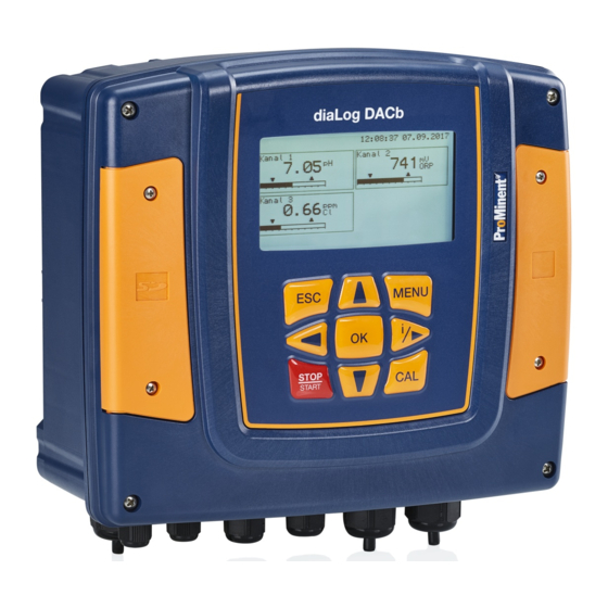
Multi-parameter controller diaLog DACb
EN
A2666
Please carefully read these operating instructions before use. · Do not discard.
The operator shall be liable for any damage caused by installation or operating errors.
The latest version of the operating instructions are available on our homepage.
982134
Target group: trained electronics technicians
BA DM 230 09/18 EN
Advertisement
Table of Contents

Related Manuals for ProMinent PROFIBUS DP DULCOMETER diaLog DACb


Summary of Contents for ProMinent PROFIBUS DP DULCOMETER diaLog DACb
- Page 1 Supplementary instructions: PROFIBUS ® DULCOMETER ® Multi-parameter controller diaLog DACb A2666 Please carefully read these operating instructions before use. · Do not discard. The operator shall be liable for any damage caused by installation or operating errors. The latest version of the operating instructions are available on our homepage. 982134 Target group: trained electronics technicians BA DM 230 09/18 EN...
- Page 2 Supplemental directives General non-discriminatory approach In order to make it easier to read, this document uses the male form in grammatical structures but with an implied neutral sense. It is aimed equally at both men and women. We kindly ask female readers for their understanding in this simplification of the text.
-
Page 3: Table Of Contents
Table of contents Table of contents Supplementary instructions PROFIBUS DP....... 4 ® 1.1 Requirements............... 4 1.2 Adjusting the controller..........4 1.2.1 General..............4 1.2.2 Configuring the PROFIBUS ® DP....... 4 1.3 Special features in active PROFIBUS ® DP opera‐ tion................5 1.3.1 General.............. -
Page 4: Supplementary Instructions Profibus
Supplementary instructions PROFIBUS ® Supplementary instructions PROFIBUS ® 1.1 Requirements Personnel must be familiar with the contents of the "Assembly and Operating Instructions for DULCOMETER ® Multi-parameter Con‐ troller diaLog DACa". The controller must have a PROFIBUS ® DP module. Validity of the supplementary instruc‐... -
Page 5: Special Features In Active Profibus
Supplementary instructions PROFIBUS ® Use the cursor keys to select the menu item ‘Bus Configuration ’ and confirm with the [OK] key ‘Configuration’ menu appears. ð The ‘Configuration’ menu, you can: In the ‘Remote configuration’ – Activating/deactivating remote configuration. ‘Address’ –... -
Page 6: Leds On The Profibus
Supplementary instructions PROFIBUS ® 1.3.3 LEDs on the PROFIBUS DP module ® LED 1 (left) - module operating status Signal Cause The module has no supply voltage or connection. Green The module and the master are exchanging information. Green flashing The module has been initialised. - Page 7 Supplementary instructions PROFIBUS ® Plugs and cables For the PROFIBUS ® DP cable, use a screened, twisted-pair cable conforming to EN 50170 (cable type A). Earthed shielding Using shielding which is earthed at one end pre‐ vents low-frequency ground loops. Shielding earthed at one end is not effective in countering HF magnetic pick-up.
-
Page 8: Operation
Supplementary instructions PROFIBUS ® Communication Communication communication Communication Plug M8x1 2 x plugs M8x1 (male) external ext. connector 2x socket M12x1 Female 4-pin external connector Socket M12x1 female (D-coded) 4-pin (D-coded) Switch alternative ext. WLAN router e.g. TP link TL-WR702N A1173 Fig. - Page 9 Supplementary instructions PROFIBUS ® 1.5.2.1 Description of the DACa data objects Tab. 3: Output data Slot Index Name Module name Identifier Data type Byte Total: count Output data ‘Channel 1’ Channel 1 0xC0.0x80 .0xC7 Measured FLOAT value Controller INT16 control var‐ iable Tempera‐...
- Page 10 Supplementary instructions PROFIBUS ® Slot Index Name Module name Identifier Data type Byte Total: count ‘Channel 3’ Channel 3 0xC0.0x80 .0xC7 Measured FLOAT value Controller INT16 control var‐ iable Tempera‐ INT16 0.1 °C ture Setpoint FLOAT Ä Chapter Channel UINT16 status 1.6.1 ‘Status of...
- Page 11 Supplementary instructions PROFIBUS ® Slot Index Name Module name Identifier Data type Byte Total: count MosFET 3 UINT16 Frequency MosFET 4 UINT16 Frequency ‘Errors’ Errors 0x40.0xC6 Error UINT32 Ä Chapter 1.6.2 ‘Error channel 1 of the channel’ on page 18 Error UINT32 Ä...
- Page 12 Supplementary instructions PROFIBUS ® Tab. 4: Input data Slot Index Name Module name Identifier Data type Byte Total: count Input data Stop / Pause (belongs to the ‘Channel1/ Channel2/ Channel3’ module) ‘Channel 1’ Stop / UINT8 Bit 7 = Stop Pause Bit 1 = channel 1...
- Page 13 Supplementary instructions PROFIBUS ® Slot Index Name Module name Identifier Data type Byte Total: count FLOAT ‘Controller Controller 0x80.0xC8 channel 2 channel 2’ Ä Chapter Configura‐ UINT16 1.6.5 ‘Set‐ tion tings of the channel configura‐ tion’ on page 21 (Parameter via bus, mode, limit value direc‐...
- Page 14 Supplementary instructions PROFIBUS ® Slot Index Name Module name Identifier Data type Byte Total: count Error UINT32 0xFFFFFFF channel 1 => all pending errors have been con‐ firmed Ä Chapter 1.6.2 ‘Error of the channel’ on page 18 Error UINT32 0xFFFFFFF channel 2 =>...
- Page 15 Supplementary instructions PROFIBUS ® Slot Index Name Module name Identifier Data type Byte Total: count Additive INT16 basic load Control UINT16 variable limit Delay after UINT16 stop Delay after UINT16 restart Remote FLOAT Only with setpoint 2 neutral zone control ‘Controller Controller 0x80.0xC5...
-
Page 16: Bit Field Definitions
Supplementary instructions PROFIBUS ® Slot Index Name Module name Identifier Data type Byte Total: count Firmware UINT32 In hexadec‐ imal format Firmware UINT32 In hexadec‐ imal format Device UINT32 In hexadec‐ serial imal format number Revision UINT16 In hexadec‐ imal format Revision UINT16 In hexadec‐... - Page 17 Supplementary instructions PROFIBUS ® Description 1 = SD card exists; 0 = no SD card 1 = local control rate 2 active; 0 = local control rate 1 active 1 = local stop active; 0 = no local stop active 1 = channel active;...
-
Page 18: Error Of The Channel
Supplementary instructions PROFIBUS ® 1.6.2 Error of the channel Description [A system error exists] Error 99: There is a system error; Error 88: The connection to the extension module is faulty; [The connection to the expansion module is faulty ] Error 34: Incorrect correction variable;... -
Page 19: Warning Of The Channel
Supplementary instructions PROFIBUS ® 1.6.3 Warning of the channel Description [The fan has an error] Warning 73: The fan has a fault; [The time must be checked] Warning 72 The time must be checked; [The battery must be replace] Warning 71 The battery needs to be replaced; Warning 4 The measuring channel is not yet calibrated;... -
Page 20: Potential-Free Relay
Supplementary instructions PROFIBUS ® 1.6.4 Potential-free relay If relay output is active, then according bit is used. Description Configuring alarm relay (XR3) Relay 2 (XR2) Relay 1 (XR1) -
Page 21: Settings Of The Channel Configuration
Supplementary instructions PROFIBUS ® 1.6.5 Settings of the channel configuration Description 1 = Channel uses remote control parameters; 0 = Channel uses internal parameters; [1 = Channel uses remote control parameters; 0 = Channel uses internal parameters] 1 = Channel uses internal set 2; 0 = Channel uses internal set 1; [1 = Use internal parameter set 2;... -
Page 22: Diagnostic Messages
Supplementary instructions PROFIBUS ® 1.7 Diagnostic messages Diagnostic telegrams In conformity with PROFIBUS standard, the device provides the ® Get_Sl_Diag service. The diagnostics data comprise standard diagnostics information (6 bytes according to PROFIBUS ® standard) and any possible diagnostics data specific to the device. A maximum of 63 bytes can be added for the device-specific diag‐... - Page 23 Supplementary instructions PROFIBUS ® Encoding user_data Order number Name CHANNEL_1 STOP CHANNEL_1 MEASUREMENT_VALUE CHANNEL_1 CONTROLLER_VALUE CHANNEL_1 TEMPERATURE CHANNEL_1 SET_POINT CHANNEL_1 STATES CHANNEL_1 WARNINGS CHANNEL_2 STOP CHANNEL_2 MEASUREMENT_VALUE CHANNEL_2 CONTROLLER_VALUE CHANNEL_2 TEMPERATURE CHANNEL_2 SET_POINT CHANNEL_2 STATES CHANNEL_2 WARNINGS CHANNEL_3 STOP CHANNEL_3 MEASUREMENT_VALUE CHANNEL_3 CONTROLLER_VALUE CHANNEL_3 TEMPERATURE CHANNEL_3 SET_POINT...
- Page 24 Supplementary instructions PROFIBUS ® Order number Name CHANNEL_1 REMOTE_XP CHANNEL_2 REMOTE_CONFIGURATION CHANNEL_2 REMOTE_LIMIT1 CHANNEL_2 REMOTE_LIMIT2 CHANNEL_2 REMOTE_SET_POINT CHANNEL_2 REMOTE_XP CHANNEL_3 REMOTE_CONFIGURATION CHANNEL_3 REMOTE_LIMIT1 CHANNEL_3 REMOTE_LIMIT2 CHANNEL_2 REMOTE_SET_POINT CHANNEL_2 REMOTE_XP CHANNEL_1 ERROR_CONFIRMATION CHANNEL_2 ERROR_CONFIRMATION CHANNEL_3 ERROR_CONFIRMATION CHANNEL_4 ERROR_CONFIRMATION Tab. 5: Error type Value Meaning 0x30...
- Page 28 ProMinent GmbH Im Schuhmachergewann 5 - 11 69123 Heidelberg Germany Telephone: +49 6221 842-0 Fax: +49 6221 842-419 Email: info@prominent.com Internet: www.prominent.com 982134, 1, en_GB © 2018...
Need help?
Do you have a question about the PROFIBUS DP DULCOMETER diaLog DACb and is the answer not in the manual?
Questions and answers