
Related Manuals for Sunny Health & Fitness SF-E3609


Summary of Contents for Sunny Health & Fitness SF-E3609
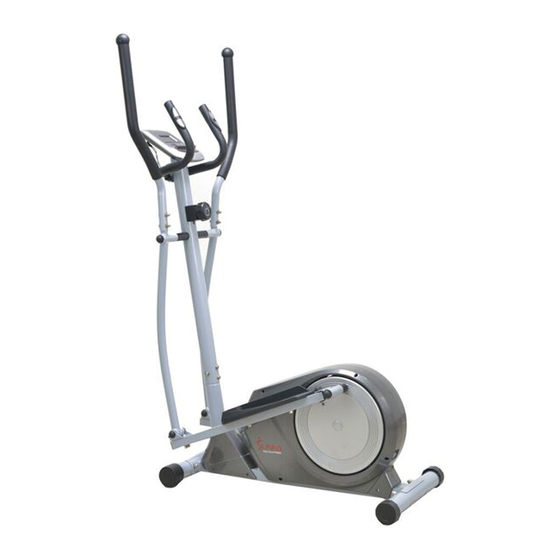
- Page 1 MAGNETIC ELLIPTICAL TRAINER SF-E3609 USER MANUAL IMPORTANT: Please read this manual carefully before using the product. Retain owner’s manual for future reference. For Customer Service, please contact: support@sunnyhealthfitness.com...
-
Page 2: Important Safety Information
IMPORTANT SAFETY INFORMATION We thank you for choosing our product. To ensure your safety and health, please use this equipment correctly. It is important to read this entire manual before assembling and using the equipment. Safe and effective use can only be achieved if the equipment is assembled, maintained and used properly. -
Page 3: Exploded Drawing
EXPLODED DRAWING 1 25 11... - Page 4 EXPLODED DRAWING 2...
-
Page 5: Parts List
PARTS LIST Description Description Computer Main frame Computer wire Rear stabilizer Screw M5*10 End cap Middle handlebar 43L/R Crank L/R Foam grip Φ23*3*445 Short spacer Φ32*Φ19.2*30 Handle pulse Link connector End cap ф25*16 Ball cap S16 Screw ST4.0*19*Φ11 Bolt M10*55*13*S17 Washer d10*Φ20*2 Handle pulse wire Grommet... - Page 6 Description Description Idler wheel Belt Magnetic force board axle Screw ST4.2*16*Φ8 φ12*61*8*45.5*M6 C Clip d12 Nut M6*H6*S10 Washer d6*Φ12*1.2 Spring washer d6 Spring washer d6 Middle axle Bolt M6*16*S10 Belt wheel Square magnet 40*25*10 Bolt M6*16*S10 Spacer Φ22*Φ18*4 Magnet location grip Spring Φ1.5*Φ15*39*N6 Bearing 6203-2RS CXSH Screw ST3*10*Φ5.6...
-
Page 7: Hardware Package
HARDWARE PACKAGE #2 M5*10 4PCS #12 M8*30*S6 2PCS #24 d8* 20*2*R16 4PCS... -
Page 8: Assembly Instructions
ASSEMBLY INSTRUCTIONS 25 11 STEP 1: Unscrew the 4 Bolts (No. 39), 4 Arc Washers (No. 33), 4 Spring Washers (No.11) and 4 Nuts (No. 25) preassembled on Front and Rear Stabilizers (No. 38 and No. 41) with Spanner (No. 62). Attach the Front and Rear Stabilizers (No. - Page 9 Fig.2 65 S6 1PC STEP 2: IMPORTANT: Turn the Tension Control Knob (No. 14A) all the way to the left (the lowest level of resistance). This provides the tension cable with the necessary length required to connect it. Unscrew the 4 Screws (No. 32), 4 Spring Washers (No. 11) and 4 Arc Washers (No. 33) preassembled on Main Frame (No.
- Page 10 #11 d8 2PCS STEP 3: Unscrew the 2 Bolts (No. 21), 2 Spring Washers (No. 11) and 2 Washers (No. 20) preassembled on Handlebar Post (No. 13) with Spanner (No. 62). Attach Swing Rods (No. 29L and 29R) to the Handlebar Post (No. 13) using 2 Bolts (No. 21), 2 Spring Washers (No.
- Page 11 STEP 4: Unscrew the 2 Nuts (No. 51) and 2 Washers (No. 50) preassembled on Main Frame (No. 40) with Spanner (No. 63). Attach Connecting Rods (No. 58L and 58R) to the Main Frame (No. 40) using 2 Nuts (No. 51) and 2 Washers (No.
- Page 12 STEP 5: Attach the left and right Pedals (No. 54L and No. 54R) to the Connecting Rods (No. 58L and No.58R) using 4 Bolts (No. 55), 4 Washers (No. 56) and 4 Nuts (No. 57). Tighten and secure with Spanner (No. 62).
- Page 13 #11 d8 4PCS #24 d8* 20*2*R16 4PCS STEP 6: Insert the left and right Handlebars (No. 26L & No. 26R) into the tops of left and right Swing Rods (No. 29L & No. 29R). Fix using 4 Bolts (No. 23), 4 Arc Washers (No. 24), 4 Spring Washers (No.11) and 4 Nuts (No.
- Page 14 #2 M5*10 4PCS #11 d8 2PCS #12 M8*30*S6 2PCS STEP 7: Unscrew the 4 Screws (No. 2) preassembled on Computer (No. 1) with Spanner (No. 62). Connect the Upper Sensor Wire (No. 34) to the Computer Wire (No. 1a). Ensure that the connection is properly secured before continuing.
- Page 15 ADJUSTING THE RESISTANCE Adjust the resistance of the machine using the Tension Control (No. 14). Increase the level of resistance by turning the tension knob to the RIGHT (clockwise), decrease the level of resistance by turning the tension knob to the LEFT (counter-clockwise).
-
Page 16: Exercise Computer
EXERCISE COMPUTER FUNCTION BUTTONS: MODE Press to select functions. To increase value of TIME, DISTANCE, CALORIES or PULSE when not in SCAN mode. DOWN To decrease value of TIME, DISTANCE, CALORIES or PULSE when not in SCAN mode. RESET Press to reset TIME, DISTANCE, CALORIES or PULSE. Hold it for 3 seconds to reset TIME, DISTANCE, CALORIES or PULSE. - Page 17 SPECIFICATIONS: AUTO SCAN Every 4 seconds TIME(TMR) 0:00~99:59 (minutes:seconds) The maximum pick-up signal CURRENT SPEED(SPD) is 999.9Mile/H FUNCTION TRIP DISTANCE(DST) 0~999.9 Miles CALORIES(CAL) 0~9999Kcal TOTAL DISTANCE(ODO) 0~999.9 Miles PULSE RATE( 40~240BPM (beat per minute) BATTERY TYPE 2PCS of SIZE-AAAor UM-4 OPERATING TEMPERATURE 0℃~+40℃...
Need help?
Do you have a question about the SF-E3609 and is the answer not in the manual?
Questions and answers