Table of Contents
Advertisement
Quick Links
Endurance Zone
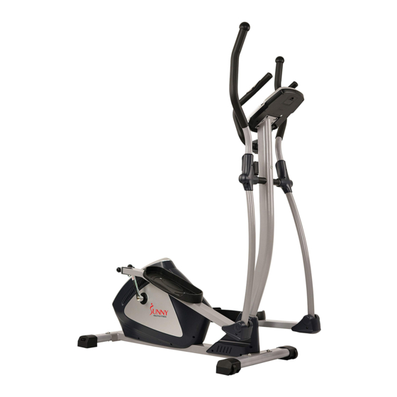
Magnetic Elliptical Trainer
SF-E3804
USER MANUAL
IMPORTANT! Please retain owner's manual for maintenance and adjustment instructions. Your
satisfaction is very important to us, PLEASE DO NOT RETURN UNTIL YOU HAVE
CONTACTED US:
support@sunnyhealthfitness.com
or 1- 877 - 90SUNNY (877-907-8669).
Advertisement
Table of Contents

Subscribe to Our Youtube Channel
Related Manuals for Sunny Health & Fitness SF-E3804


Summary of Contents for Sunny Health & Fitness SF-E3804
- Page 1 Endurance Zone Magnetic Elliptical Trainer SF-E3804 USER MANUAL IMPORTANT! Please retain owner’s manual for maintenance and adjustment instructions. Your satisfaction is very important to us, PLEASE DO NOT RETURN UNTIL YOU HAVE CONTACTED US: support@sunnyhealthfitness.com or 1- 877 - 90SUNNY (877-907-8669).
-
Page 2: Important Safety Information
IMPORTANT SAFETY INFORMATION We thank you for choosing our product. To ensure your safety and health, please use this equipment correctly. It is important to read this entire manual before assembling and using the equipment. Safe and effective use can only be achieved if the equipment is assembled, maintained and used properly. It is your responsibility to ensure that all users of the equipment are informed of all warnings and precautions. -
Page 3: Exploded Diagram
EXPLODED DIAGRAM 1... - Page 4 EXPLODED DIAGRAM 2...
-
Page 5: Hardware Package
HARDWARE PACKAGE #39 M8*50 4PCS #50 M8*75 2PCS #34 d8*Φ20*1.5 12PCS #52 M8*45 4PCS #35 M8*16 4PCS #16 M8*40 4PCS #10 d8 2PCS #17 d8*Φ16*1.5*R30 4PCS #11 M8*30 2PCS #18 M8 10PCS #60 1/2" 2PCS # 57/64 L/R 1/2" 2PCS #58 d17 2PCS #63 S19 2PCS # 62/65 L/R 1/2"... -
Page 6: Parts List
PARTS LIST Description Spec. Qty. Description Spec. Qty. Computer Tension Cable Link Wire Sensor Wire Computer Handlebar (L/R) Main Frame 2L/R End Cap Screw M8*50 Foam Grip (L/R) Washer D10*Φ20*2 Enc Cap Φ25 Front Stabilizer Middle Handlebar Left End Cap Foam Grip Right End Cap Pulse... - Page 7 Description Spec. Qty. Description Spec. Qty. Chain Cover (L/R) Right Crank C-Clip Bearing Bearing Axle Spacer Spring Washer Crank Cover 2 Washer D6*Φ12*1 Belt Wheel C-Clip Steel Bracket Axle Screw M8*25 Tension Spring Idler Wheel Magnetic Board End Cap Magnet Belt Hexagon Bolt M6*16...
-
Page 8: Assembly Instructions
ASSEMBLY INSTRUCTIONS STEP 1: #39 M8*50 4PCS Attach Front Stabilizer (No. 41) and Rear #34 d8*Φ20*1.5 4PCS Stabilizer (No. 46) onto Main Frame (No. 38) with 4 Screws (No. 39) and 4 Washers (No. 34). Tighten and secure with Allen Wrench (No. - Page 9 STEP 3: #19 M8*20 2PCS Remove pre-assembled 2 Hexagon Bolts #10 d8 2PCS (No. 19), 2 Spring Washers (No. 10) and 2 Washers (No. 20) from Upright Post (No. #20 d8*Φ32*2 2PCS 33) with Spanner (No. B). Slide Swing Rods (No. 26L/R) onto Upright S13-14-15 Post (No.
- Page 10 STEP 5: #52 M8*45 4PCS Attach Pedals (No. 53) onto the Pedal Tubes #34 d8*Φ20*1.5 4PCS (No. 51) with 4 Hexagon Bolts (No. 52), 4 Washers (No. 34) and 4 Nylon Nuts (No. 18). #18 M8 4PCS Tighten and secure with Spanner (No. B) S13-14-15 STEP 6: #16 M8*40 4PCS...
- Page 11 STEP 7: M8*30 2PCS Attach Middle Handlebar (No. 6) to #10 d8 2PCS Upright Post (No. 33) with 2 Screws (No. 11) and 2 Spring Washers (No. 10). Tighten and secure with Allen wrench (No. A). Then attach Small Cover (No. 12) onto Middle Handlebar (No.
- Page 12 STEP 9: M5*10 4PCS Remove pre-assembled 4 Screws (No. 28) from the back of Computer (No. 1). Connect Trunk Wire (No. 29) with Link Wire of Computer (No. 1b). Then attach Computer (No. 1) to the Upright Post (NO. 33) with 4 Screws (No. 28). Tighten and secure with Spanner (No.
- Page 13 ADJUSTMENTS & USAGE GUIDE ADJUSTING THE BALANCE In order to achieve a smooth and comfortable ride, you must ensure that the stability of the bike is secured. If you notice that the bike is unbalanced during use, you should adjust the End Caps (No. 45) located on the rear stabilizer until the bike becomes level with the floor surface.
-
Page 14: Troubleshooting
TROUBLESHOOTING PROBLEM SOLUTION Remove the computer and verify the wire that comes from the computer is properly connected to the wire that comes from the There is no display on the computer. upright post. Check if the batteries are correctly positioned and battery springs are in proper contact with batteries. -
Page 15: Exercise Computer
EXERCISE COMPUTER FUNCTION BUTTONS MODE 1. Press the button to select hour, minute, year, month and date for setting. 2. Press the button to select TIME, DISTANCE, CALORIES and PULSE to preset. 3. Press the button for selection function display on main LCD, or enter after setting. -
Page 16: Operation Order
Note : This data is a rough guide for comparison of different exercise sessions which can not be used in medical treatment. PULSE The monitor will display the user's heart rate in beats per minute during training. You may set the target heart rate by press the SET & MODE button. CALENDAR The monitor will display date, month, and year when the monitor is in sleep mode. - Page 17 conductors to start the body fat testing. 9-4. It takes few seconds to test the body fat. If you did not hold on the conductor during the testing procedure, the LCD will show the error sign Err after 10 seconds period. 9-5.
Need help?
Do you have a question about the SF-E3804 and is the answer not in the manual?
Questions and answers