Table of Contents

Subscribe to Our Youtube Channel
Related Manuals for Sunny Health & Fitness SF-E3416


Summary of Contents for Sunny Health & Fitness SF-E3416
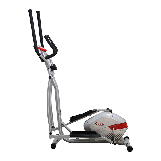
- Page 1 MAGNETIC ELLIPTICAL TRAINER SF-E3416 USER MANUAL IMPORTANT: Please read this manual carefully before using the product. Retain owner’s manual for future reference. For Customer Service, please contact: support@sunnyhealthfitness.com...
-
Page 2: Important Safety Information
IMPORTANT SAFETY INFORMATION We thank you for choosing our product. To ensure your safety and health, please use this equipment correctly. It is important to read this entire manual before assembling and using the equipment. Safe and effective use can only be achieved if the equipment is assembled, maintained and used properly. -
Page 3: Exploded Drawing
EXPLODED DRAWING 30 36... -
Page 4: Parts List
PARTS LIST Description Qty No. Description Computer Bolt M8*65*30*S14 Spacer 14*8.3*48 Middle handlebar Foam grip 23*5*445 Alloy wrap 1 32*3*28*16*14 End cap 25*16 Bolt M10*42*20*S17 Washer d6*12*1 U shape plate Arc washer d6*20*1.5*R30 Screw ST4*19 Handle post for tube *25 Washer d8*16*1.5 Screw M8*30*S6 Nylon nut M8*H7.5*S13... - Page 5 PARTS LIST Description Qty No. Description Ball cap S13 Allen wrench S8 Ball cap S18 Allen wrench S6 Ball cap S16 Spanner S13-14-15 Nylon nut M10*H9.5*S17 Spanner S17-S19 (inner 17) Wave washer d17*25*0.3 Handlebar post Rear stabilizer Computer wire NOTE: Most of the listed assembly hardware has been packaged separately, but some hardware items have been preinstalled on the machine in.
-
Page 6: Hardware Package
HARDWARE PACKAGE... -
Page 7: Assembly Instructions
ASSEMBLY INSTRUCTIONS #19 M8*H16*S13 4pcs #28 M8*60*20*H5 4pcs #29 d8* 20*2*R30 4pcs STEP: 1 Attach the Front and Rear Stabilizers (No. 27 and No. 65) to the Main Frame (No. 59) using 4 Carriage Bolts (No. 28), 4 Arc Washers (No. 29) and 4 Nuts (No. 19), tighten with Spanner (No. - Page 8 STEP: 2 IMPORTANT: Before attempting to connect the tension control cable, ensure that the Tension Control (No. 52A) is turned all the way to the left (the lowest level of resistance), this will provide the tension cable with the necessary length required to connect it.
- Page 9 ¦ µ ¦ µ #60 S13 6PCS #62 S16 2PCS #61 S18 2PCS STEP: 3 Secure Swing Rods (No. 25L and 25R) to the Handlebar Post (No. 64) using 2 Bolts (No. 24), 2 Spring Washers (No. 23) and 2 Washers (No. 22), tighten with Spanner (No.
- Page 10 ALTERNATE INSTALLATION METHOD: STEP: 1 Disconnect Link Connector Combination (No. 47) from the Connecting Rod (No. 55). STEP: 2 Insert Hinge Bolt L (No. 45) and Hinge Bolt R (No. 40) through the Wave Washers (No. 70), then through hole Link Connector Combination (No.
- Page 11 Φ STEP: 4 Attach the left and right Pedals (No. 43L/R) to the Connecting Rods (No. 55) using 4 Bolts (No. 17), 4 Washers (No. 37) and 4 Nylon Nuts (No. 38), tighten and secure with Spanner (No. 68).
- Page 12 ¦ µ STEP: 5 Insert the left and right Handlebars (No. 13L/R) into the left and right Swing Rods (No. 24L/R), fix using 2 Bolts (No. 17), 2 Arc Washers (No. 18) and 2 Nuts (No. 19). Tighten with Spanner (No. 68).
- Page 13 STEP: 6 Attach the Middle Handlebar (No. 2) to the clamp located on the Handlebar Post (No. 64) using 2 Screws (No. 8) and 2 Spring Washers (No. 23), tighten with Allen Wrench (No. 67), then cover the clamp using Clamp Cover (No. 42). Connect the Upper Sensor Wire (No.
-
Page 14: Exercise Computer
EXERCISE COMPUTER SPECIFICATIONS: TIME …………………………………...00:00-99:59 MIN: SEC SPEED ……………………………….. 0.0-999.9 KM/H or ML/H DISTANCE ……………………………0.00-99.99 KM or ML CALORIES ……………………………0.0-999.9 KCAL PULSE ……………………………….. 40-240 BPM FUNCTION KEY: MODE: Press to select function. (Time, Speed, Distance, Calories, Pulse). OPERATION PROCEDURES: 1. AUTO ON/OFF: If the belt is put into motion, or the mode button is pressed the computer will become active, and shall remain active while either of these two things continues to be done, however without any signal for approximately 4 minutes, power (monitor), will turn off...
Need help?
Do you have a question about the SF-E3416 and is the answer not in the manual?
Questions and answers